SOLIDWORKS 18 BOx TOp SHEET METAL TOOLBOx pAgE 2-2
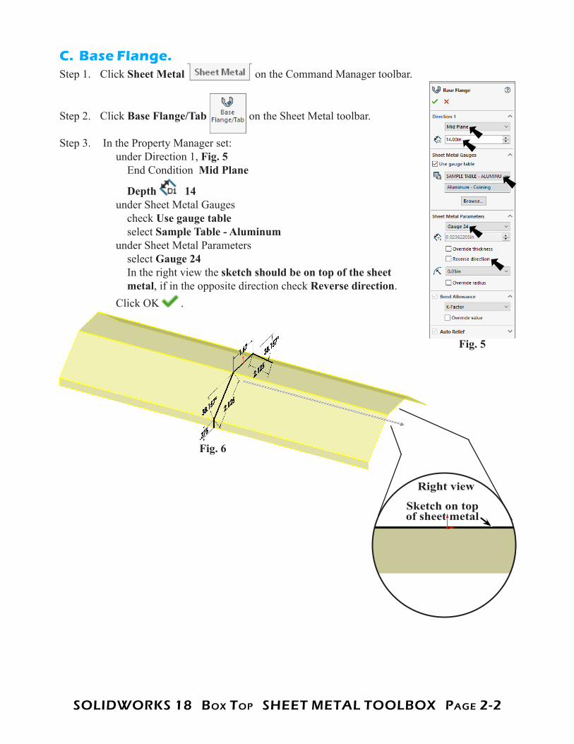
C. Base Flange.Step 1. Click Sheet Metal on the Command Manager toolbar.
Step 2. Click Base Flange/Tab on the Sheet Metal toolbar.
Step 3. In the Property Manager set: under Direction 1, Fig. 5 End Condition Mid Plane
Depth 14 under Sheet Metal Gauges check Use gauge table select Sample Table - Aluminum under Sheet Metal Parameters select Gauge 24 In the right view the sketch should be on top of the sheet metal, if in the opposite direction check Reverse direction. Click OK .
Fig. 5
Fig. 6
Right view
Sketch on top of sheet metal
SOLIDWORKS 18 BOx TOp SHEET METAL TOOLBOx pAgE 2-3
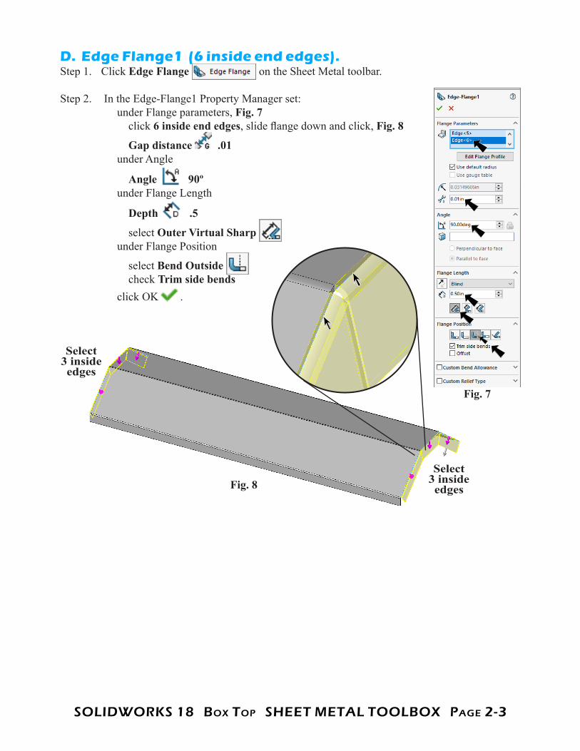
D. Edge Flange1 (6 inside end edges).Step 1. Click Edge Flange on the Sheet Metal toolbar.
Step 2. In the Edge-Flange1 Property Manager set: under Flange parameters, Fig. 7 click 6 inside end edges, slide flange down and click, Fig. 8
Gap distance .01 under Angle
Angle 90º under Flange Length
Depth .5
select Outer Virtual Sharp under Flange Position
select Bend Outside check Trim side bends click OK .
Fig. 7
Fig. 8Select
3 inside edges
Select 3 inside edges
SOLIDWORKS 18 BOx TOp SHEET METAL TOOLBOx pAgE 2-4
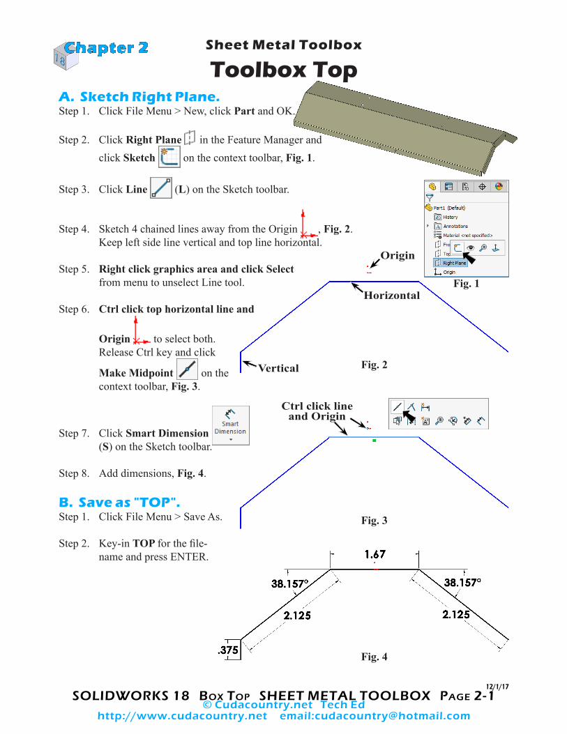
E. Cut.Step 1. Click Right Plane in the Feature Manager and click Sketch
on the context toolbar, Fig. 9.
Step 2. Click Normal To on the Standard Views toolbar. (Ctrl-8)
Step 3. Click Line (L) on the Sketch toolbar.
Step 4. Sketch horizontal line across both bottom corners and a diagonal con-necting them, Fig. 10.
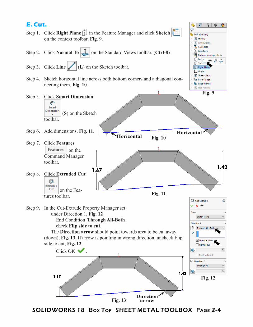
Step 5. Click Smart Dimension
(S) on the Sketch toolbar.
Step 6. Add dimensions, Fig. 11.
Step 7. Click Features on the
Command Manager toolbar.
Step 8. Click Extruded Cut
on the Fea-tures toolbar.
Step 9. In the Cut-Extrude Property Manager set: under Direction 1, Fig. 12 End Condition Through All-Both check Flip side to cut. The Direction arrow should point towards area to be cut away (down), Fig. 13. If arrow is pointing in wrong direction, uncheck Flip side to cut, Fig. 12. Click OK .
Fig. 9
Fig. 10HorizontalHorizontal
Fig. 11
Fig. 12
Fig. 13Direction
arrow
SOLIDWORKS 18 BOx TOp SHEET METAL TOOLBOx pAgE 2-5
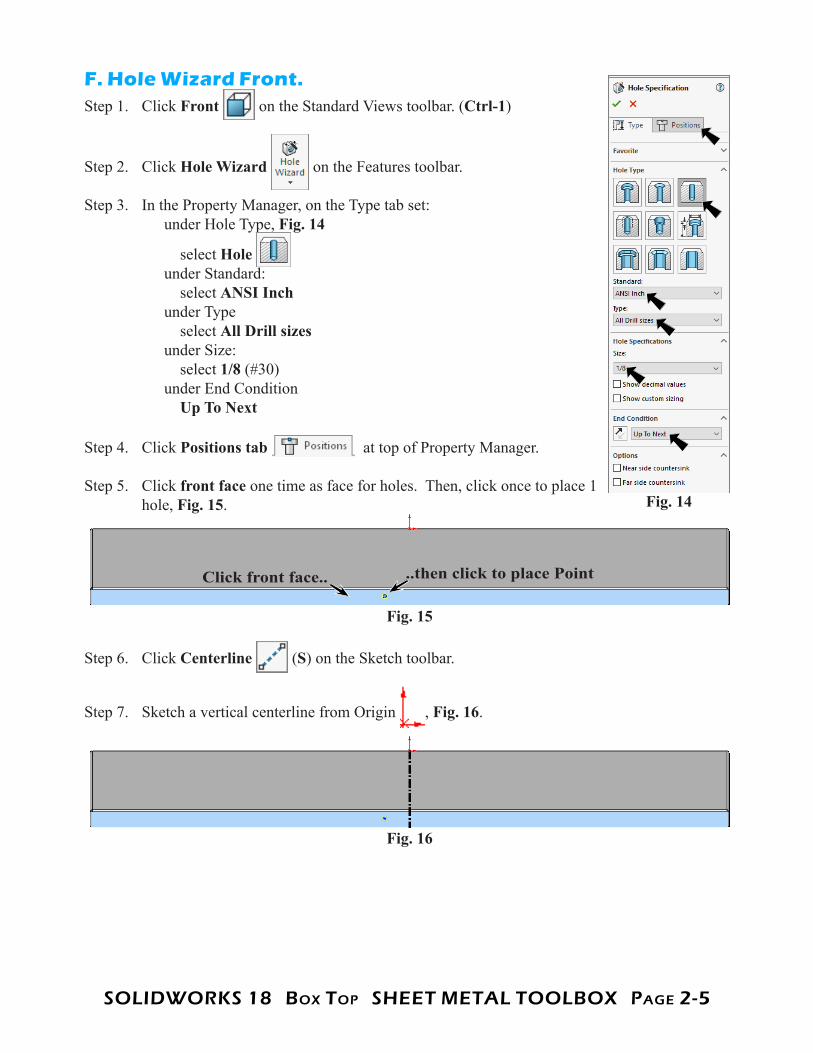
F. Hole Wizard Front.Step 1. Click Front on the Standard Views toolbar. (Ctrl-1)
Step 2. Click Hole Wizard on the Features toolbar.
Step 3. In the Property Manager, on the Type tab set: under Hole Type, Fig. 14
select Hole under Standard: select ANSI Inch under Type select All Drill sizes under Size: select 1/8 (#30) under End Condition Up To Next
Step 4. Click Positions tab at top of Property Manager.
Step 5. Click front face one time as face for holes. Then, click once to place 1 hole, Fig. 15.
Step 6. Click Centerline (S) on the Sketch toolbar.
Step 7. Sketch a vertical centerline from Origin , Fig. 16.
Fig. 14
Fig. 15
Click front face.. ..then click to place Point
Fig. 16
SOLIDWORKS 18 BOx TOp SHEET METAL TOOLBOx pAgE 2-6
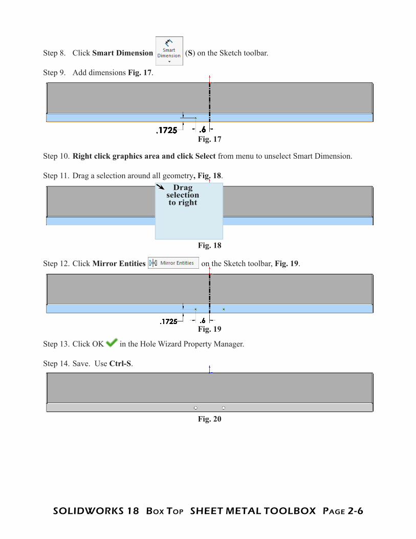
Step 8. Click Smart Dimension (S) on the Sketch toolbar.
Step 9. Add dimensions Fig. 17.
Step 10. Right click graphics area and click Select from menu to unselect Smart Dimension.
Step 11. Drag a selection around all geometry, Fig. 18.
Step 12. Click Mirror Entities on the Sketch toolbar, Fig. 19.
Step 13. Click OK in the Hole Wizard Property Manager.
Step 14. Save. Use Ctrl-S.
Fig. 17
Fig. 18
Fig. 19
Fig. 20
Drag selection to right
SOLIDWORKS 18 BOx TOp SHEET METAL TOOLBOx pAgE 2-7
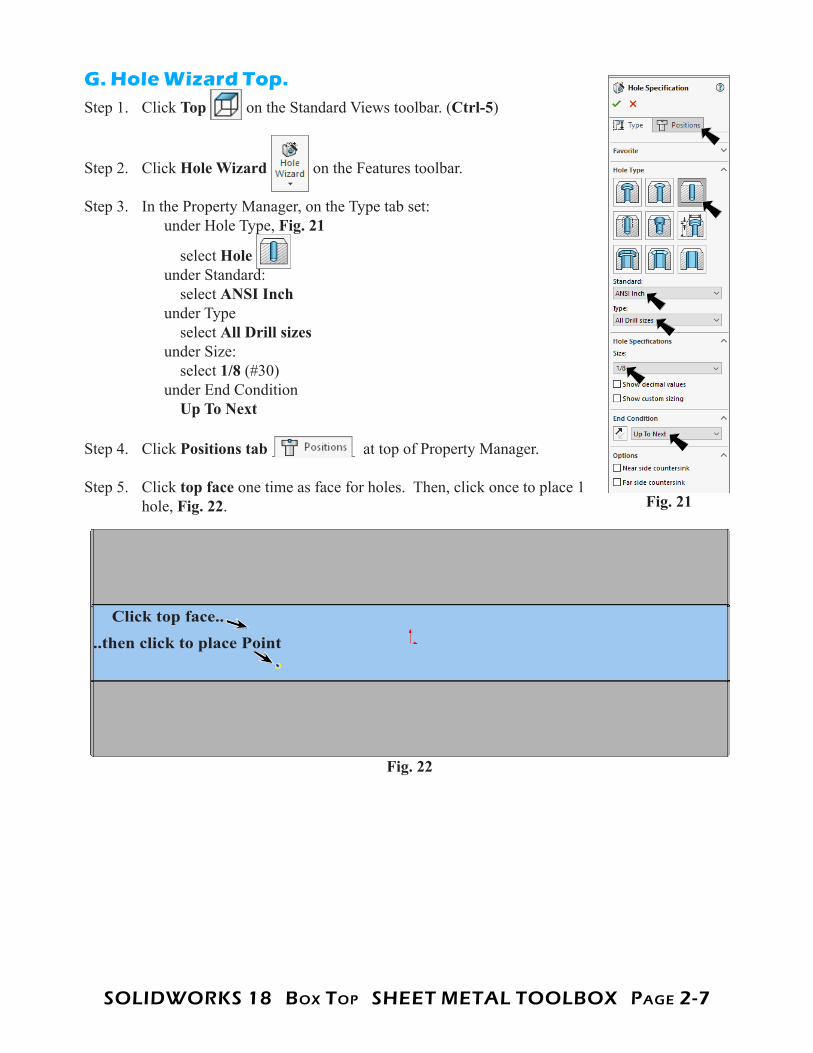
G. Hole Wizard Top.Step 1. Click Top on the Standard Views toolbar. (Ctrl-5)
Step 2. Click Hole Wizard on the Features toolbar.
Step 3. In the Property Manager, on the Type tab set: under Hole Type, Fig. 21
select Hole under Standard: select ANSI Inch under Type select All Drill sizes under Size: select 1/8 (#30) under End Condition Up To Next
Step 4. Click Positions tab at top of Property Manager.
Step 5. Click top face one time as face for holes. Then, click once to place 1 hole, Fig. 22. Fig. 21
Fig. 22
Click top face..
..then click to place Point
SOLIDWORKS 18 BOx TOp SHEET METAL TOOLBOx pAgE 2-8
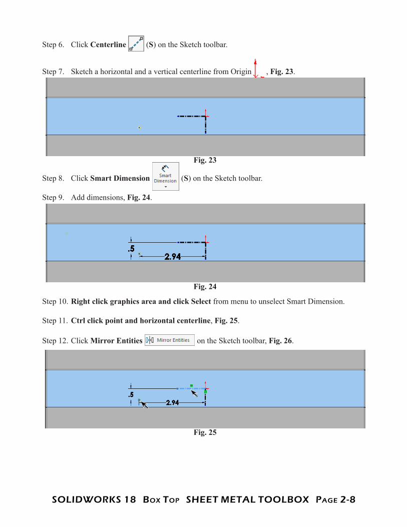
Step 6. Click Centerline (S) on the Sketch toolbar.
Step 7. Sketch a horizontal and a vertical centerline from Origin , Fig. 23.
Step 8. Click Smart Dimension (S) on the Sketch toolbar.
Step 9. Add dimensions, Fig. 24.
Step 10. Right click graphics area and click Select from menu to unselect Smart Dimension.
Step 11. Ctrl click point and horizontal centerline, Fig. 25.
Step 12. Click Mirror Entities on the Sketch toolbar, Fig. 26.
Fig. 23
Fig. 24
Fig. 25
SOLIDWORKS 18 BOx TOp SHEET METAL TOOLBOx pAgE 2-9
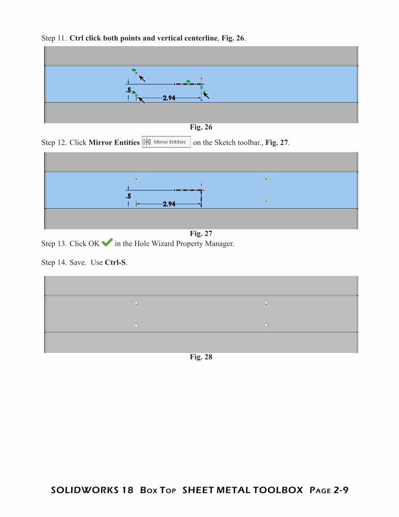
Step 11. Ctrl click both points and vertical centerline, Fig. 26.
Step 12. Click Mirror Entities on the Sketch toolbar., Fig. 27.
Step 13. Click OK in the Hole Wizard Property Manager.
Step 14. Save. Use Ctrl-S.
Fig. 26
Fig. 27
Fig. 28
SOLIDWORKS 18 BOx TOp SHEET METAL TOOLBOx pAgE 2-10
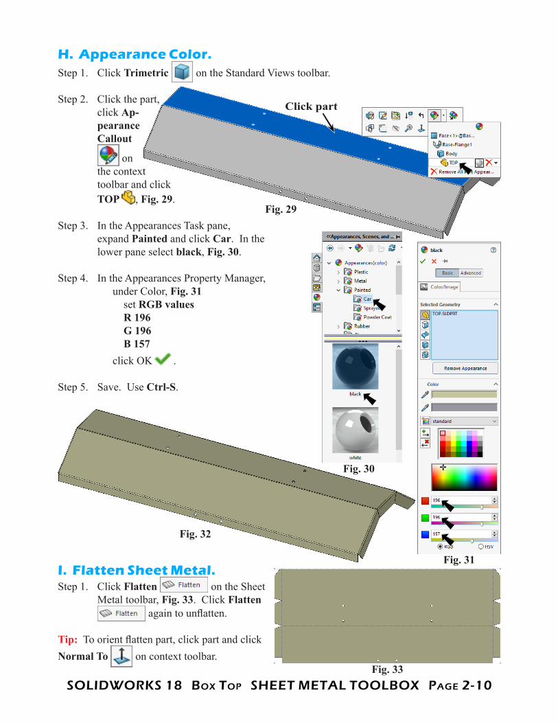
H. Appearance Color.Step 1. Click Trimetric on the Standard Views toolbar.
Step 2. Click the part, click Ap-pearance Callout
on the context toolbar and click TOP , Fig. 29.
Step 3. In the Appearances Task pane, expand Painted and click Car. In the lower pane select black, Fig. 30.
Step 4. In the Appearances Property Manager, under Color, Fig. 31 set RGB values R 196 G 196 B 157 click OK .
Step 5. Save. Use Ctrl-S.
I. Flatten Sheet Metal.Step 1. Click Flatten on the Sheet
Metal toolbar, Fig. 33. Click Flatten again to unflatten.
Tip: To orient flatten part, click part and click Normal To on context toolbar.