Anatomy of a transition metal complex (Modern Formulas) A transition metal complex has several parts as can be seen in the following scheme: (1) a central metal atom, (2) ligands, (3) it may possess a counter ion such as an anion. [Cu(NH 3 ) 4 ]SO 4 Central Metal Atom Ligands Anion
Transcript
Anatomy of a transition metal complex (Modern Formulas)
A transition metal complex has several parts as can be seen in the following scheme:
(1) a central metal atom, (2) ligands, (3) it may possess a counter ion such as an anion.
[Cu(NH3)4]SO4
Central Metal Atom Ligands Anion
Alternatively, and more rarely, a metal complex may actually be an anion instead of a cation.
K2[Fe(Cl)6]
Central Metal AtomLigands
Cation
In this case, the iron complex is an anion, and it needs two potassium cations to balance its charge. It may dissolve in water to produce:
waterK2[Fe(Cl)6] 2 K+ + [Fe(Cl)6]2-
Transition metals and their compounds or complexes have characteristic properties such as:
(a) variable oxidation states, (b) small, compact atoms, which decrease across a period and then
increases towards the end (c) stable compounds of varying covalency in far more numerous
examples, geometries and types than do the metals from the main group,
(d) magnetic properties such as paramagnetism and diamagnetism, (e) highly colored complexes that span the rainbow (names of some of
the transition metals express this fact---iridium, rhodium, chromium, etc.),
(f) catalytic activity such as with enzymes and industrially used catalysts and
(g) variable coordination geometries such as square planar complexes, which are unknown for the main group metals. It is the study of these fascinating properties of the transition metals and their coordination chemistry that is the focus of this book.
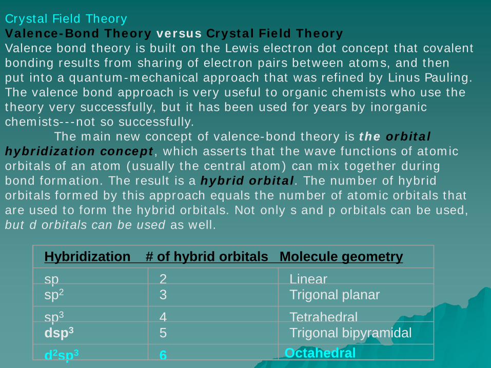
Crystal Field TheoryValence-Bond Theory versus Crystal Field TheoryValence bond theory is built on the Lewis electron dot concept that covalent bonding results from sharing of electron pairs between atoms, and then put into a quantum-mechanical approach that was refined by Linus Pauling. The valence bond approach is very useful to organic chemists who use the theory very successfully, but it has been used for years by inorganic chemists---not so successfully.
The main new concept of valence-bond theory is the orbital hybridization concept, which asserts that the wave functions of atomic orbitals of an atom (usually the central atom) can mix together during bond formation. The result is a hybrid orbital. The number of hybrid orbitals formed by this approach equals the number of atomic orbitals that are used to form the hybrid orbitals. Not only s and p orbitals can be used, but d orbitals can be used as well.
Electron Counting FormalismsIn the chapter on atomic structure in freshman chemistry we say that in the 4th period of the periodic table the orbitals are filled in the order [Ar]4s23d10 for the transition metals. This turns out to be true only for isolated metal atoms that are not in a compound. If a metal ion is surrounded by an electronic field---by surrounding it with ligands---then the 3d-orbitals drop in energy and fill before the 4s orbitals.
Thus, an organometallic chemist naturally considers that the transition metal valence electrons are all d-electrons.
If we ask for the d-electron count on a transition metal such as Nb in the zero oxidation state, we call it d5, not d3. For zero-valent metals, we see that the electron count corresponds to the column it occupies in the periodic table. Therefore, Co is in the ninth column and is d9 (not d7) and Tc3+ is d4 (seventh column for Tc, and subtract three electrons). Since we can now assign a d-electron count to a metal center, we can determine the electronic contribution of the surrounding ligands in a metal complex and come up with an overall electron count.
The Ionic Charge Convention (ICC Method)
The basic premise of this metal-complex electron counting method is that we first remove all of the ligands from the metal with the proper number of electrons for each ligand to bring it to a closed valence shell state, which is usually an octet.
For example, if we remove water from a metal complex, H2O has a completed octet and acts as a neutral molecule. When it was bonded to the metal center it did so through its lone pair and there is no need to change the oxidation state of the metal to balance charge. We therefore call water a neutral two-electron donor.
By contrast however, if we remove a chlorine group from the metal and complete its octet, then we formally have chloride (Cl-). If we bond this chloride anion to the metal, the new lone pair forms our metal-chlorine bond and the chloride acts as a two-electron donor ligand. We must do the same thing with a ligand such as a methyl group -CH3. In the case of a methyl group, the -CH3 must come away from the metal as a methanide anion (CH3
-
), so that the carbon can maintain an octet.
It is important to notice in these last examples using anionic ligands that to keep electrical charge neutrality we must formally oxidize the metal by one electron by assigning a positive charge to the metal. This reduces the d-electron count of the metal center by one electron.
The Neutral Covalent Convention (NCC Method)
The basic premise of this metal-complex electron counting method is that when we remove one of the ligands from the metal, rather than take the ligand to a closed shell state, we make it neutral. Let's consider water once again. When we remove it from the metal, it is a neutral molecule with one lone pair of electrons. Therefore, as with the ionic charge convention method, water is a neutral two-electron donor.
We diverge from the ionic method when we consider a ligand such as chlorine or methyl. When we remove chlorine from the metal and make the chlorine fragment neutral, we have a neutral chlorine radical (Cl•) rather than a chloride ion. Both the metal and the chlorine radical must donate one electron each to form the metal-ligand bond.
Therefore, the chlorine group is a one-electron donor, not a two-electron donor as it is under the ionic convention. We must do the same thing with a ligand such as the methyl group -CH3. In the case of a methyl group, the -CH3 must come away from the metal as a methyl radical (CH3•), so that the methyl group is electrically neutral.
In the neutral covalent convention, metals retain their full complement of d electrons because we never change the oxidation state from zero when we count electrons; i.e. Co will always count for 9 electrons regardless of the oxidation state and Nb will always count for five.
Using the ICC Method to Calculate Oxidation State
In a metal complex the oxidation state of the metal is calculated by determining the difference in the number of valence electrons in the zero oxidation state of the metal with the number of electrons present after the loss or removal of the ligands in their closed Lewis electron dot structures.
For example we can calculate the oxidation state of the metals for: [MnO4]-, [PtF6], [Cr(NH3)6]3+, [Cr(CO)5]2- .
For [MnO4]- : Mno has 7 e-’s, 7
overall charge on the complex is -1, +1
remove 8- charges for four O2- - 8
electrons left on the Mn 0
The difference between the number of valence electrons on the metal (7) minus the number after removal of ligands (0): (7) – (0) = +7 is the oxidation state of Mn. Thus Mn(VII)
For [Cr(NH3)6]3+ : Cro has 6 e-’s, 6
overall charge on the complex is +3 , -3
remove 0 charges for NH3 0
electrons left on the Cr +3
The difference between the number of valence electrons on the metal (6) minus the number after removal of ligands (3): (6) – (3) = +3 is the oxidation state of Cr. Thus Cr(III).
For [Cr(CO)5]2- : Cro has 6 e-’s, 6
overall charge on the complex is -2 , +2
remove 0 charges for CO 0
electrons left on the Cr +8
The difference between the number of valence electrons on the metal (6) minus the number after removal of ligands (8): (6) – (8) = -2 is the oxidation state of Cr. Thus Cr-2 .
Crystal Field Theory
There are two things that set the study of the electronic structures of transition metal compounds apart from the body of valence theory.
One is the presence of partly filled d subshells. This leads to experimental observations not possible in most organic chemistry: paramagnetism, visible absorption spectra, and apparent irregular variations in thermodynamic and structural properties.
The second is that there is a crude but effective approximation, called crystal field theory that provides a powerful yet simple method of understanding and correlating all of those properties that arise primarily from the presence of the partly filled d subshells.
The crystal field theory provides a way of determining how the energies of the metal ion orbitals will be affected by the set of surrounding atoms or ligands by simple electrostatic considerations.
Crystal field theory is a model and not a realistic description of the forces actually at work, and is completely superseded by molecular orbital theory. With that being said, its simplicity and convenience have earned it a cherished place in the coordination chemist’s “toolbox.”
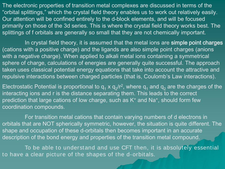
The electronic properties of transition metal complexes are discussed in terms of the “orbital splittings,” which the crystal field theory enables us to work out relatively easily. Our attention will be confined entirely to the d-block elements, and will be focused primarily on those of the 3d series. This is where the crystal field theory works best. The splittings of f orbitals are generally so small that they are not chemically important.
In crystal field theory, it is assumed that the metal ions are simple point charges(cations with a positive charge) and the ligands are also simple point charges (anions with a negative charge). When applied to alkali metal ions containing a symmetrical sphere of charge, calculations of energies are generally quite successful. The approach taken uses classical potential energy equations that take into account the attractive and repulsive interactions between charged particles (that is, Coulomb’s Law interactions).
Electrostatic Potential is proportional to q1 x q2/r2, where q1 and q2 are the charges of the interacting ions and r is the distance separating them. This leads to the correct prediction that large cations of low charge, such as K+ and Na+, should form few coordination compounds.
For transition metal cations that contain varying numbers of d electrons in orbitals that are NOT spherically symmetric, however, the situation is quite different. The shape and occupation of these d-orbitals then becomes important in an accurate description of the bond energy and properties of the transition metal compound.
To be able to understand and use CFT then, it is absolutely essential to have a clear picture of the shapes of the d-orbitals.
One of the main differences between the three p orbitals and the five dorbitals is that the set of p orbitals has three identical orbitals oriented along the x, y, and z axes whereas the set of five d orbitals has four identical orbitals (dxy, dyz, dxz, and dx
2- y
2) and one (the dz2) that looks like it
is special; that is, it appears to be rather different from the other four.
X-axis
Y-axis Z-axis
Y-axisX-axisX-axis
Y-axis
Z-axis
X-axis
Y-axis
Z-axis
dxy dxz dyz
dx2-y2 dz2
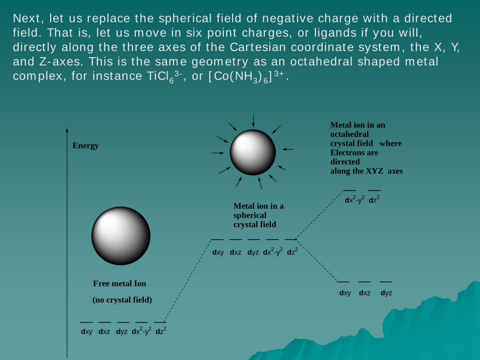
Let us build a metal complex up from a free, gaseous metal ion with no ligands around it. The five d-orbitals in a gaseous metal ion are degenerate and have the same energy; this is illustrated in the following energy diagram. If a spherical field of negative charges (a so-called crystal field) is placed around the metal ion, then the energy of the d-electrons in the d-orbitals is increased because of electrostatic repulsion but the five d-orbitals are still degenerate.
__ __ __ __ __
__ __ __ __ __
__ __
__ __ __
dxy dxz dyz dx2-y2 dz2
dxy dxz dyz
dx2-y2 dz2
Free metal Ion
(no crystal field)
Metal ion in a sphericalcrystal field
Metal ion in anoctahedralcrystal field whereElectrons are directed along the XYZ axes
dxy dxz dyz dx2-y2 dz2
Energy
X-axis X-axis
Z-axis
Z-axis
Y-axis
Y-axis
X-axis
Y-axis
Z-axis
Y-axis
Z-axis
X-axis
X-axis
Y-axis
Z-axis
Y-axis
Z-axis
X-axis
dxy orbital
dxz orbital dyz orbital
X-axis
Y-axis
Z-axis
Y-axis
Z-axis
X-axis
X-axis
Y-axis
Z-axis
Y-axis
X-axis
Z-axis
dx2-y2 orbital dz2 orbital
Next, let us replace the spherical field of negative charge with a directed field. That is, let us move in six point charges, or ligands if you will, directly along the three axes of the Cartesian coordinate system, the X, Y, and Z-axes. This is the same geometry as an octahedral shaped metal complex, for instance TiCl63-, or [Co(NH3)6]3+.
__ __ __ __ __
__ __ __ __ __
__ __
__ __ __
dxy dxz dyz dx2-y2 dz2
dxy dxz dyz
dx2-y2 dz2
Free metal Ion
(no crystal field)
Metal ion in a sphericalcrystal field
Metal ion in anoctahedralcrystal field whereElectrons are directed along the XYZ axes
dxy dxz dyz dx2-y2 dz2
Energy
In this octahedral case, things change dramatically. The five d-orbitals are no longer degenerate, and electrons in those d-orbitals that have lobes extending along the X, Y, and Z axes (dx2-y2 and dz2) will experience greater repulsion due to these “incoming” ligands as compared to the electrons in the d-orbitals that have lobes that lie between the X, Y, and Z axes (dxy, dyz and dxz). This is called crystal field splitting.
__
__ __
__ __ __dxy dxz dyz
dx2-y2 dz2
________
10Dq =
4Dq
6Dq
eg set
t2g set
5 d-orbitals
octahedralcrystal fieldsplitting
o
The result of these differences for the d-orbitals is an energy difference between the dz2 and dx2-y2 orbitals compared to the dxy, dyz and dxz orbitals called 10Dq by definition, or ∆o, which can vary in energy depending on metal and ligands, but is typically in the range of 100-300 kj/mol. This splitting energy is typified by an increase in energy for the two orbitals lying along the axes, called the eg set, and a decrease in energy for the three orbitals lying in between the axes, called the t2g set. The egset is increased in energy by 6 Dq from the “barycenter” and the t2g set is decreased by 4 Dq.
__
__ __
__ __ __dxy dxz dyz
dx2-y2 dz2
________
10Dq =
4Dq
6Dq
eg set
t2g set
5 d-orbitals
octahedralcrystal fieldsplitting
o
__
__ __
__ __ __dxy dxz dyz
dx2-y2 dz2
________
Stabilizedby -8Dq
5 d-orbitals
octahedralcrystal fieldsplitting for a d2 metal ion
For a metal complex that has two d-electrons (d2), then the CFSE would be twice as much, or -8Dq, (See HUND’s RULE).
Electrons that are admitted into the t2g set are therefore stabilizing for octahedral metal complexes.
An octahedral metal complex with three d-electrons (d3) would then have a CFSE that would be -12 Dq.
__
__ __
__ __ __dxy dxz dyz
dx2-y2 dz2
________
Stabilizedby -12Dq
5 d-orbitals
octahedralcrystal fieldsplitting for a d3 metal ion
In the cases where there are four d-electrons (d4) there are two possibilities that arise. In the case where 10Dq is less than the pairing energy for two electrons in the same orbital, the fourth electron will occupy one of the higher energy eg orbitals, and in the case where 10Dq is greater than the pairing energy, the fourth electron will pair up in one of the t2g orbitals.
These are called the weak field case and the strong field case respectively. These cases are shown below with a relative illustration of the orbital energy splitting.
eg set
t2g set
__
__ __
__ __ __
________
eg set
t2g set
__
__ __
__ __ __
________
Weak Field Case Strong Field Case
10Dq less than pairing energy
10Dq greater than pairing energy
The option for weak field or strong field is only available with d4 through d7 metal complexes.
For the cases shown above there are different numbers of paired and unpaired d-electrons. For the weak field case, there are four unpaired electrons, whereas in the strong field case there are only two unpaired electrons. The electron configurations can be written in this manner:
Weak field d4 = t2g3 eg
1 is also called high spinStrong field d4 = t2g
4 eg0 is also called low spin
Therefore, the weak field case is also called high spin, and the strong field case is also called low spin because of the lower number of unpaired electrons.
The two possible cases where an octahedral metal complex can have a d5 electron configuration are shown below:
a d5 metal ion
eg set
t2g set
__
__ __
__ __ __
________
eg set
t2g set
__
__ __
__ __ __
________
Weak Field Case Strong Field Case
10Dq less than pairing energy
10Dq greater than pairing energy
a d6 metal ion
eg set
t2g set
__
__ __
__ __ __
________
eg set
t2g set
__
__ __
__ __ __
________
Weak Field Case Strong Field Case
10Dq less than pairing energy
10Dq greater than pairing energy
a d7 metal ion
eg set
t2g set
__
__ __
__ __ __
________
eg set
t2g set
__
__ __
__ __ __
________
Weak Field Case Strong Field Case
10Dq less than pairing energy
10Dq greater than pairing energy
The d6 and d7
electron configurations are shown below:
The d6 strong field case has the maximum CFSE.
a d8 metal ion
eg set
t2g set
__
__ __
__ __ __
________
eg set
t2g set
__
__ __
__ __ __
________
Weak Field Case Strong Field Case
10Dq less than pairing energy
10Dq greater than pairing energy
a d9 metal ion
eg set
t2g set
__
__ __
__ __ __
________
eg set
t2g set
__
__ __
__ __ __
________
Weak Field Case Strong Field Case
10Dq less than pairing energy
10Dq greater than pairing energy
The d8 and d9
configurations show NO DIFFERENCE in their electron configurations in the weak and strong field cases; the electron configuration for d8
is t2g6eg
2, and for d9 it is t2g
6eg3.
Crystal Field Stabilization Energies for the Octahedral Geometry
The CFT approach can be easily extended to other geometries and the next most important case is tetrahedral.
The ∆td splitting of the d-orbitals is much smaller than ∆o on the order of: ∆td =4/9∆o since there are only four ligands around a tetrahedral complex compared to six on octahedral complexes, which reduces overall repulsion, and since the ligands are not as efficiently directed at the d-orbitals.
Octahedral
The scheme below depicts the Cartesian coordinate system with a hypothetical cube drawn around it, and then next a tetrahedral metal complex at the origin of the coordinate system, where the ligands are found at the corners of the hypothetical cube. Since the ligands are at the corners of the cube, no d-orbitals are directed towards them.
X-axis
Y-axis
Z-axis
Y-axis
Z-axis
X-axis
X-axis
Y-axis
Z-axis
Y-axis
Z-axis
X-axis
Ligands
This can be illustrated by drawing a couple of representative d-orbitals into this scheme. For illustrative purposes and brevity, only the dz2 and the dxz orbitals are shown, representative of the e set and the t set of orbitals.
As can be discerned from the complicated scheme below, the e set of orbitals (dz2 and the dx2-y2) have a lesser interaction with the ligands (1/2 face of cube away) than does the t set of orbitals (dxy, dyz, dxz) (1/2 of edge away).
X-axis
Y-axis
Z-axis
Y-axis
Z-axis
X-axis
X-axis
Y-axis
Z-axis
Y-axis
Z-axis
X-axis
Less repulsion with ligands
dz2 orbitalfrom e set
dxz orbitalfrom t set
More repulsion with ligands
Since this is the reverse of the octahedral case, the d-orbital splitting diagram is reversed as seen below. Overall, the d-orbital splitting is not nearly as strong as in the octahedral case!
td
t2g
e
eg
Oht2
This can be illustrated with the tetrahedral complex ion [CoCl4 ]2-. The ion contains Co2+. You should be able to determine that for yourself at this point. The Co(II) ion has a d7 electron configuration. The splitting of the d-orbitals will be small since this is a tetrahedral complex, giving the weak field/ high spin case shown in the scheme below. The compound [CoCl4 ]2- exhibits paramagnetism, with three unpaired electrons.
e set
t2 set
__
__ __
__ __ __
________
TetrahedralGeometry
Weak Field Case
10Dq less than pairing energy
The square planar case can be considered as an extension of the octahedral field, where we remove the two ligands from the Z-axis.
t2g
eg
Oh
Octahedral Square Planar
dxz, dyz
dz2
dx2-y2
dxy
Consequently, repulsion of an electron in the dz2 orbital will no longer be equivalent to that experienced by an electron in the dx2-y2 orbital, and the end result is shown above. In this text, the only square planar complexes will be for d8 complexes, i.e. nearly all four coordinate complexes exhibit tetrahedral geometry except for d8 metal complexes, which may be tetrahedral or square planar.
__________
__ __
__
__
__
dx2-y2
dxz, dyz
dxy
dz2
Square Planar Geometry
Strong Field
An example of a square planar complex is [Ni(CN)4]2- . The Ni(II) is d8, so the splitting diagram is:
In this case, there are no unpaired electrons; the compound is considered to be diamagnetic.
Jahn-Teller Effect
The Jahn-Teller theorem states that any species with an electronically degenerate ground state will distort to remove the degeneracy. Compounds exhibit the Jahn-Teller effect by displaying a distortion of their coordination geometry as the degeneracy of the ground state is “broken”.
eg set
t2g set
__ __
__ __ __
Expected electron configuration for d9 metal in an
octahedral geometry
Electron configurationafter Jahn-Teller
distortion
__
__ __
__
__
dx2-y2
dz2
dxy
dxzdyz
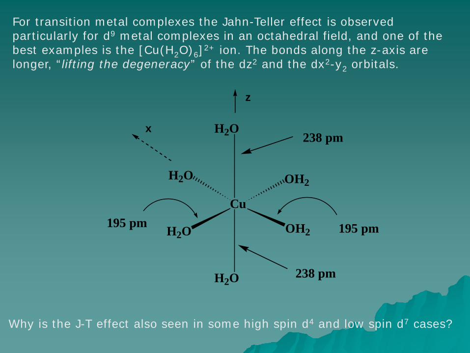
For transition metal complexes the Jahn-Teller effect is observed particularly for d9 metal complexes in an octahedral field, and one of the best examples is the [Cu(H2O)6]2+ ion. The bonds along the z-axis are longer, “lifting the degeneracy” of the dz2 and the dx2-y2 orbitals.
Cu
H2O OH2
H2O OH2
H2O
H2O
195 pm
238 pm
z
238 pm
195 pm
x
Why is the J-T effect also seen in some high spin d4 and low spin d7 cases?
Trends in Crystal Field Theory
A trend in the value of ∆o can be determined for metal ions which is independent of the ligands. This trend is:
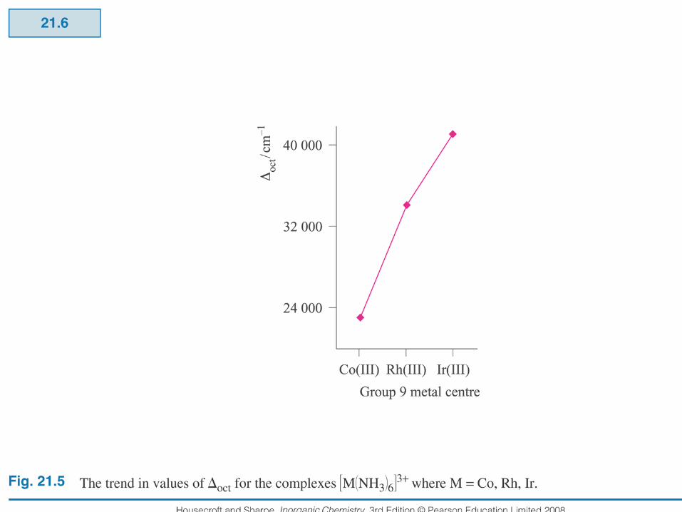
Mn(II) < Ni(II) < Co(II) < Fe(III) < Cr(III) < Co(III) < Ru(III) < Mo(III) < Rh(III) < Ir(III) < Pt(IV). The trend follows roughly the oxidation state of the metals (+3 has a higher field than +2 for the same metal and ligand), then it increases down a group.
Generally, ∆o increases with increasing oxidation state of the metals but, this is an empirical generalization and crystal field theory just cannot explain the magnitudes of ∆o values. Generally, complexes of the 2nd
and 3rd row of the periodic table almost always form strong field complexes, so Crystal Field Theory is best for 1st row transition metal complexes.
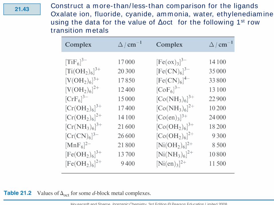
Construct a more-than/less-than comparison for the ligandsOxalate ion, fluoride, cyanide, ammonia, water, ethylenediamineusing the data for the value of Δoct for the following 1st row transition metals


![Effective Hamiltonian Crystal Field for Magnetic ... · arXiv:1301.1036v2 [physics.chem-ph] 24 Mar 2013 Effective Hamiltonian Crystal Field for Magnetic Interactions in Polynuclear](https://static.documents.pub/doc/80x56/6037d3da026d297c7e7cb25b/eiective-hamiltonian-crystal-field-for-magnetic-arxiv13011036v2-24-mar.jpg)


