52
Chapter 23 Mirrors and Lenses
| Date post: | 17-Dec-2015 |
| Category: |
Documents |
| Upload: | melvyn-berry |
| View: | 230 times |
| Download: | 0 times |
Chapter 23
Mirrors and Lenses
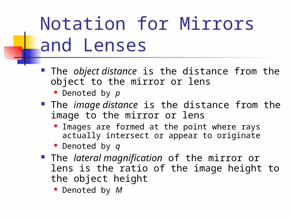
Notation for Mirrors and Lenses The object distance is the distance from the
object to the mirror or lens Denoted by p
The image distance is the distance from the image to the mirror or lens
Images are formed at the point where rays actually intersect or appear to originate
Denoted by q The lateral magnification of the mirror or lens
is the ratio of the image height to the object height
Denoted by M

Types of Images for Mirrors and Lenses A real image is one in which light
actually passes through the image point Real images can be displayed on screens
A virtual image is one in which the light does not pass through the image point The light appears to diverge from that
point Virtual images cannot be displayed on
screens
More About Images To find where an image is formed,
it is always necessary to follow at least two rays of light as they reflect from the mirror

Flat Mirror Simplest possible
mirror Properties of the image
can be determined by geometry
One ray starts at P, follows path PQ and reflects back on itself
A second ray follows path PR and reflects according to the Law of Reflection

Properties of the Image Formed by a Flat Mirror The image is as far behind the mirror as the
object is in front q = p
The image is unmagnified The image height is the same as the object height
h’ = h and M = 1 The image is virtual The image is upright
It has the same orientation as the object There is an apparent left-right reversal in the
image
Application – Day and Night Settings on Auto Mirrors
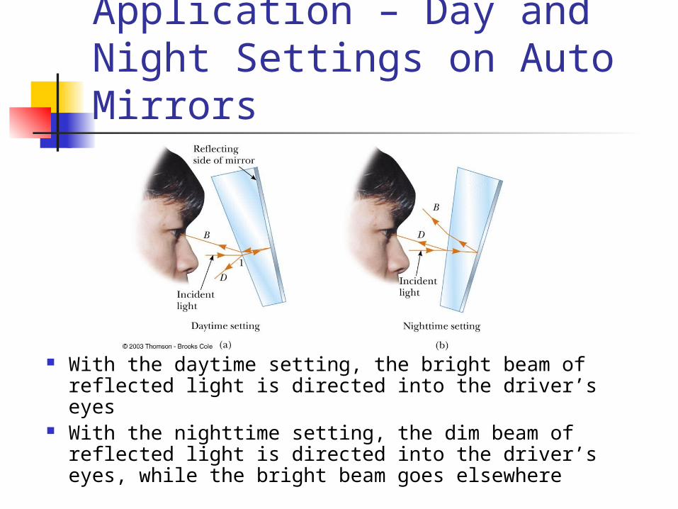
With the daytime setting, the bright beam of reflected light is directed into the driver’s eyes
With the nighttime setting, the dim beam of reflected light is directed into the driver’s eyes, while the bright beam goes elsewhere

Spherical Mirrors A spherical mirror has the shape of a
segment of a sphere A concave spherical mirror has the
silvered surface of the mirror on the inner, or concave, side of the curve
A convex spherical mirror has the silvered surface of the mirror on the outer, or convex, side of the curve

Concave Mirror, Notation The mirror has a
radius of curvature of R
Its center of curvature is the point C
Point V is the center of the spherical segment
A line drawn from C to V is called the principle axis of the mirror

Spherical Aberration
Rays are generally assumed to make small angles with the mirror
When the rays make large angles, they may converge to points other than the image point
This results in a blurred image
This effect is called spherical aberration

Image Formed by a Concave Mirror Geometry can be used to
determine the magnification of the image
h’ is negative when the image is inverted with respect to the object
'h qM
h p

Image Formed by a Concave Mirror
Geometry shows the relationship between the image and object distances
This is called the mirror equation
1 1 2p q R

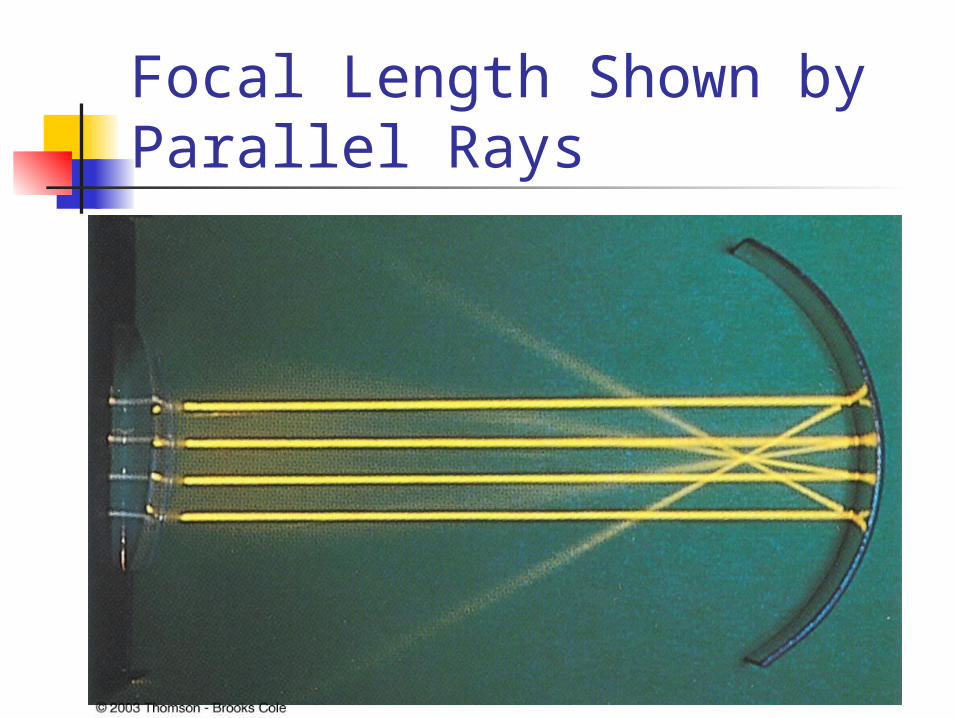
Focal Length If an object is very far
away, then p= and 1/p = 0
Incoming rays are essentially parallel
In this special case, the image point is called the focal point
The distance from the mirror to the focal point is called the focal length
The focal length is ½ the radius of curvature
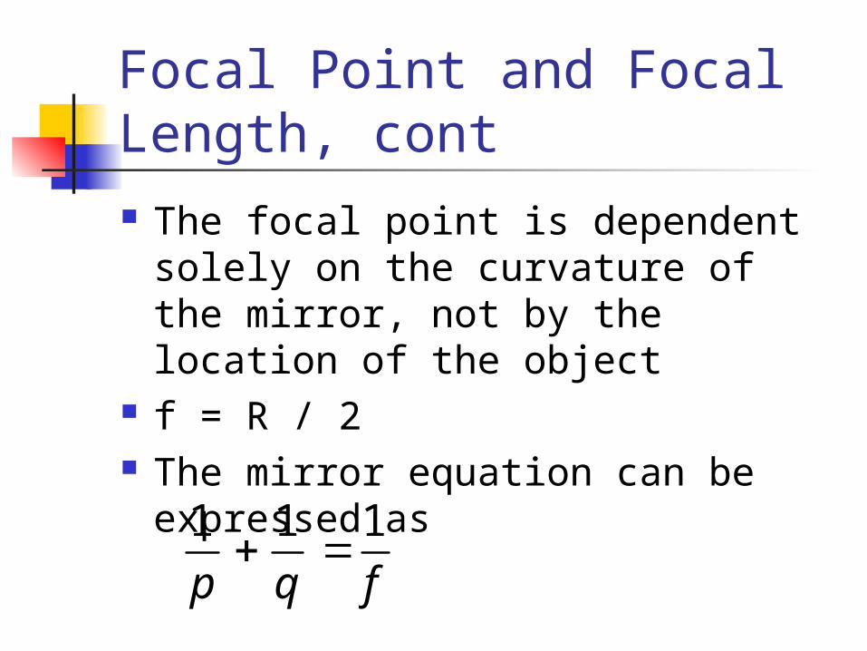
Focal Point and Focal Length, cont The focal point is dependent solely
on the curvature of the mirror, not by the location of the object
f = R / 2 The mirror equation can be
expressed as1 1 1p q f
Focal Length Shown by Parallel Rays
Convex Mirrors A convex mirror is sometimes called a
diverging mirror The rays from any point on the object
diverge after reflection as though they were coming from some point behind the mirror
The image is virtual because it lies behind the mirror at the point where the reflected rays appear to originate
In general, the image formed by a convex mirror is upright, virtual, and smaller than the object

Image Formed by a Convex Mirror

Sign Conventions for Mirrors
Ray Diagrams A ray diagram can be used to determine
the position and size of an image They are graphical constructions which
tell the overall nature of the image They can also be used to check the
parameters calculated from the mirror and magnification equations

Drawing A Ray Diagram To make the ray diagram, you need to
know The position of the object The position of the center of curvature
Three rays are drawn They all start from the same position on the
object The intersection of any two of the rays at a
point locates the image The third ray serves as a check of the
construction
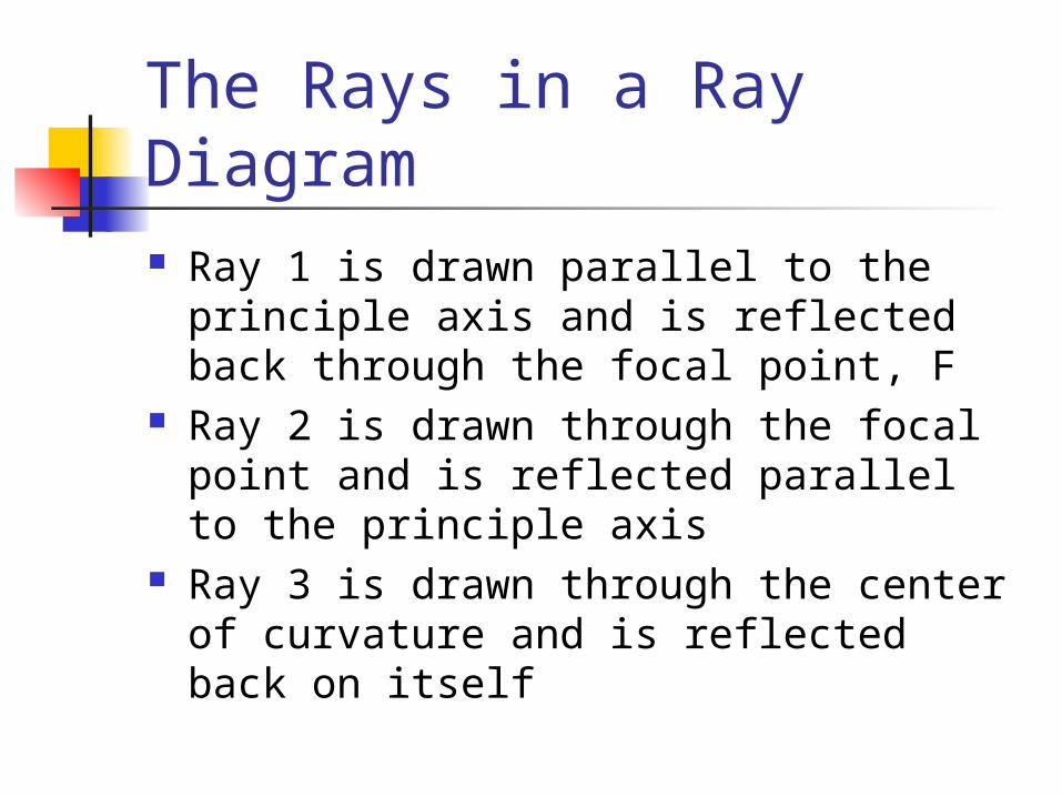
The Rays in a Ray Diagram Ray 1 is drawn parallel to the principle
axis and is reflected back through the focal point, F
Ray 2 is drawn through the focal point and is reflected parallel to the principle axis
Ray 3 is drawn through the center of curvature and is reflected back on itself

Notes About the Rays The rays actually go in all
directions from the object The three rays were chosen for
their ease of construction The image point obtained by the
ray diagram must agree with the value of q calculated from the mirror equation

Ray Diagram for Concave Mirror, p > R
The object is outside the center of curvature of the mirror
The image is real The image is inverted The image is smaller than the object

Ray Diagram for a Concave Mirror, p < f
The object is between the mirror and the focal point
The image is virtual The image is upright The image is larger than the object

Ray Diagram for a Convex Mirror
The object is in front of a convex mirror The image is virtual The image is upright The image is smaller than the object
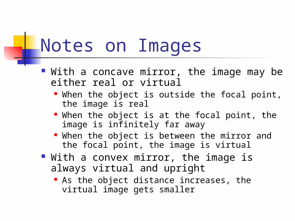
Notes on Images With a concave mirror, the image may be
either real or virtual When the object is outside the focal point, the
image is real When the object is at the focal point, the image
is infinitely far away When the object is between the mirror and the
focal point, the image is virtual With a convex mirror, the image is always
virtual and upright As the object distance increases, the virtual
image gets smaller
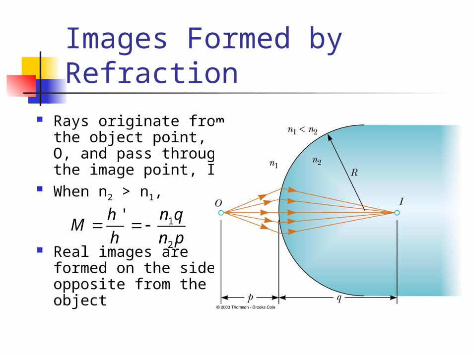
Images Formed by Refraction
Rays originate from the object point, O, and pass through the image point, I
When n2 > n1,
Real images are formed on the side opposite from the object
1
2
' n qhM
h n p
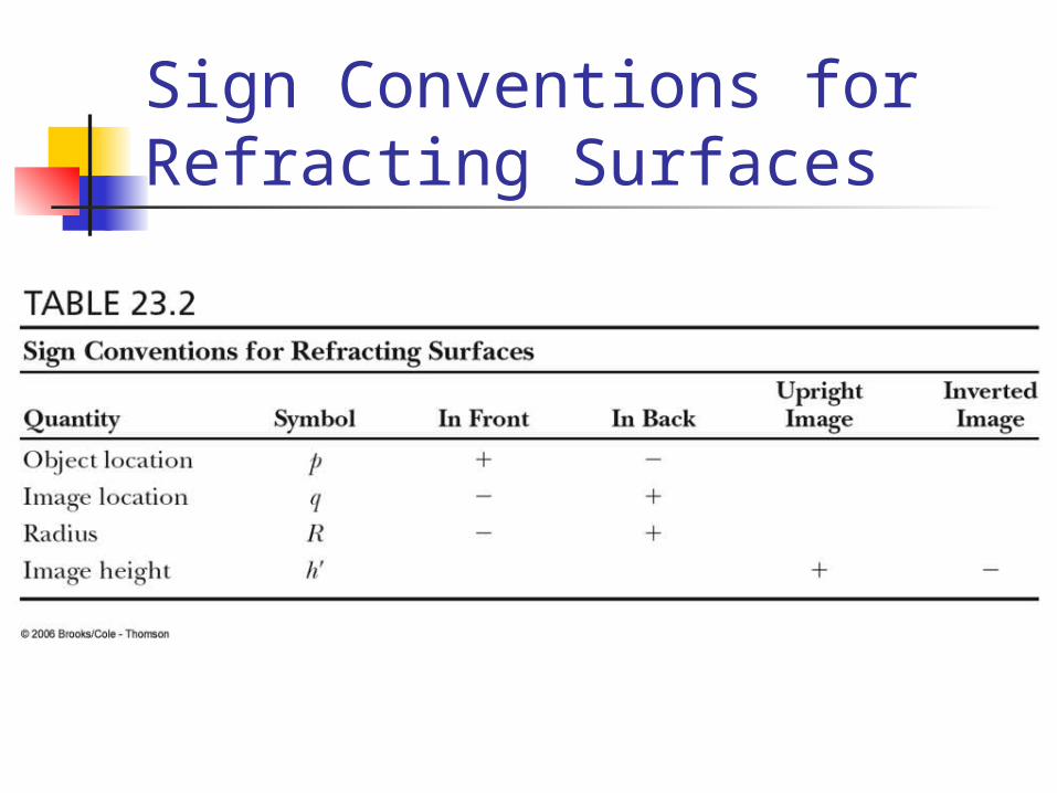
Sign Conventions for Refracting Surfaces

Flat Refracting Surface The image formed by
a flat refracting surface is on the same side of the surface as the object
The image is virtual The image forms
between the object and the surface
The rays bend away from the normal since n1 > n2

Atmospheric Refraction There are many interesting results
of refraction in the atmosphere Sunsets Mirages
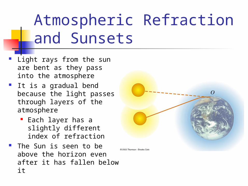
Atmospheric Refraction and Sunsets
Light rays from the sun are bent as they pass into the atmosphere
It is a gradual bend because the light passes through layers of the atmosphere
Each layer has a slightly different index of refraction
The Sun is seen to be above the horizon even after it has fallen below it
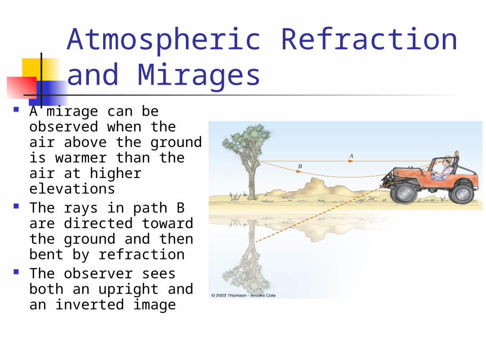
Atmospheric Refraction and Mirages
A mirage can be observed when the air above the ground is warmer than the air at higher elevations
The rays in path B are directed toward the ground and then bent by refraction
The observer sees both an upright and an inverted image
Thin Lenses A thin lens consists of a piece of
glass or plastic, ground so that each of its two refracting surfaces is a segment of either a sphere or a plane
Lenses are commonly used to form images by refraction in optical instruments
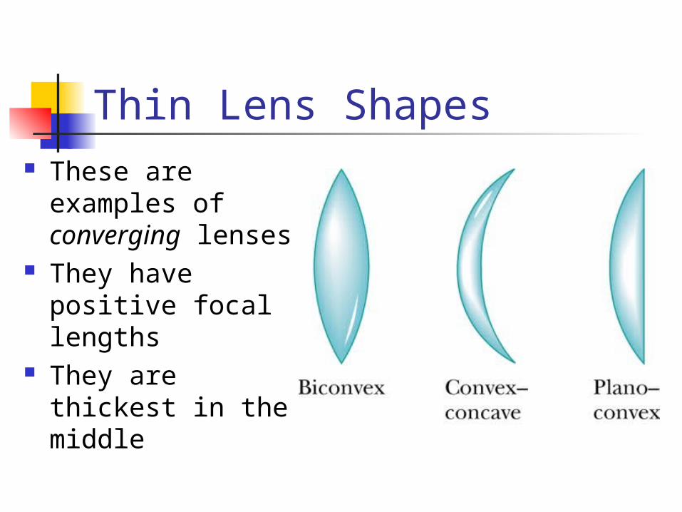
Thin Lens Shapes These are
examples of converging lenses
They have positive focal lengths
They are thickest in the middle

More Thin Lens Shapes
These are examples of diverging lenses
They have negative focal lengths
They are thickest at the edges

Focal Length of Lenses The focal length, ƒ, is the image
distance that corresponds to an infinite object distance This is the same as for mirrors
A thin lens has two focal points, corresponding to parallel rays from the left and from the right A thin lens is one in which the distance
between the surface of the lens and the center of the lens is negligible

Focal Length of a Converging Lens
The parallel rays pass through the lens and converge at the focal point
The parallel rays can come from the left or right of the lens
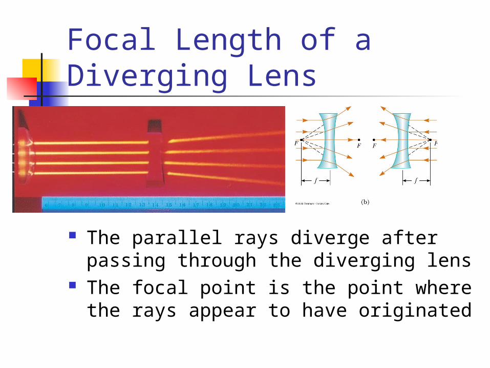
Focal Length of a Diverging Lens
The parallel rays diverge after passing through the diverging lens
The focal point is the point where the rays appear to have originated

Lens Equations The geometric
derivation of the equations is very similar to that of mirrors
'
1 1 1
h qM
h p
p q f
Lens Equations The equations can be used for both
converging and diverging lenses A converging lens has a positive focal
length A diverging lens has a negative focal
length
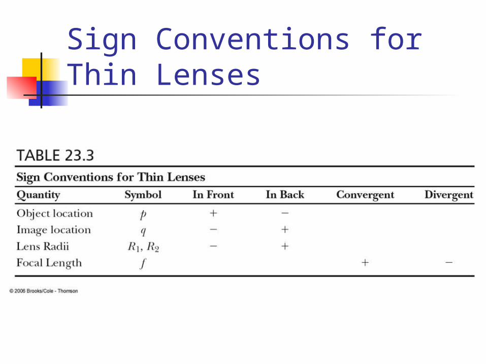
Sign Conventions for Thin Lenses
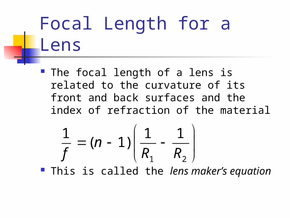
Focal Length for a Lens The focal length of a lens is related to
the curvature of its front and back surfaces and the index of refraction of the material
This is called the lens maker’s equation
1 2
1 1 1( 1)n
f R R
Ray Diagrams for Thin Lenses Ray diagrams are essential for understanding
the overall image formation Three rays are drawn
The first ray is drawn parallel to the first principle axis and then passes through (or appears to come from) one of the focal lengths
The second ray is drawn through the center of the lens and continues in a straight line
The third ray is drawn from the other focal point and emerges from the lens parallel to the principle axis
There are an infinite number of rays, these are convenient
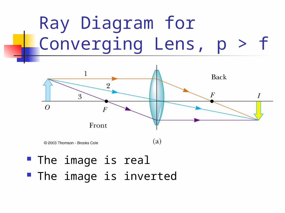
Ray Diagram for Converging Lens, p > f
The image is real The image is inverted

Ray Diagram for Converging Lens, p < f
The image is virtual The image is upright

Ray Diagram for Diverging Lens
The image is virtual The image is upright

Combinations of Thin Lenses
The image produced by the first lens is calculated as though the second lens were not present
The light then approaches the second lens as if it had come from the image of the first lens
The image of the first lens is treated as the object of the second lens
The image formed by the second lens is the final image of the system
Combination of Thin Lenses, 2 If the image formed by the first lens lies
on the back side of the second lens, then the image is treated at a virtual object for the second lens p will be negative
The overall magnification is the product of the magnification of the separate lenses
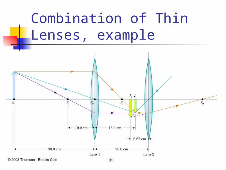
Combination of Thin Lenses, example
Lens and Mirror Aberrations One of the basic problems is the
imperfect quality of the images Largely the result of defects in shape
and form Two common types of aberrations
exist Spherical aberration Chromatic aberration

Spherical Aberration Results from the
focal points of light rays far from the principle axis are different from the focal points of rays passing near the axis
For a mirror, parabolic shapes can be used to correct for spherical aberration

Chromatic Aberration Different wavelengths of
light refracted by a lens focus at different points
Violet rays are refracted more than red rays
The focal length for red light is greater than the focal length for violet light
Chromatic aberration can be minimized by the use of a combination of converging and diverging lenses


