39
Chapter 26 Sequence Design, Artifacts and Nomenclature Yongquan Ye, Ph.D. Assist. Prof. Radiology, SOM Wayne State University

Chapter 26Sequence Design, Artifacts and Nomenclature
Yongquan Ye, Ph.D.Assist. Prof.Radiology, SOMWayne State University

• Previous classes:▫ RF pulse, Gradient, Signal Readout
▫ Gradient echo, spin echo, inversion recovery, etc
▫ K-space concept, filling trajectory and phase consistency
• Today’s content ▫ MR sequence components
▫ Sequence design and imaging parameters, how it is actually done
▫ Tricks and artifacts
▫ Sequence examples and nomenclature

MRI sequence 1, 2, 3 (literally)• Essential MRI Sequence components:▫ RF pulse▫ Gradient▫ ADC
• Peripheral ▫ Patient positioning▫ Imaging processor▫ Etc

MRI sequence 1, 2, 3 (literally)
• Sequence functionalities▫ Signal excitation▫ Signal preparation/manipulation/
modulation▫ Signal acquisition
• What is a MR sequence?

Sequence examples
2D Spin Echo RARE (Fast Spin Echo)
3D GRE GRE-EPI SE-EPI
(Berstein, et al. 2004)
(E. Mark Haacke, et al. 1999)

Generating RF pulse
Patent US8269499
An ideal RF pulse creates a spatially homogeneous electromagnetic field, denoted as B1

Using RF pulse to create Mxy• Basic Bloch Equation
i.e. M precesses around any external magnetic fields
• A RF pulse creates an electromagnetic field, i.e. B1field, with frequency also of 0=B0
Lab Frame Rotating Frame

RF pulse properties• On- / off- resonant: rf =/≠ 0
• Flip angle: tipping effect of the RF pulse
• Frequency response: Fourier transform of B1(t)
• Bandwidth: within which spins are considered on-resonant
BW BW
(E. Mark Haacke, et al. 1999)

Types of RF pulse• Functionality▫ Excitation (needed for all; =0-/2)▫ Refocusing (for spin echo; =/2-)▫ Inversion (IR; for T1W, tissue nulling; =)
(Berstein, et al. 2004)
ExcitationIR
Refocusing

Types of RF pulse• Temporal shape. i.e. B1(t)▫ Sinc (widely used for spatially selective imaging)▫ Rectangular (non-selective excitation or IR)▫ Gaussian (Saturation, MTC)▫ VERSE (variable rate selective excitation)▫ Composite pulses (SLR)▫ etc…
B1(t)
B1(f)
Sinc VERSE SLRGaussianRect

Types of RF pulse• Selectivity▫ Selective (soft):
Narrow BW with well defined frequency response, e.g. sinc pulseExample: Tsinc = 5.12ms w/ 4 zero crossing => BW ≈ 780Hz
▫ Non-selective (hard):Very broad BW, e.g. rectangular pulseExample: Trect = 100s => BW ≈ 12100Hz
B1(t)
B1(f)
Sinc Rect

• Special purpose RF pulses▫ Selective excitation/saturation pulse (water or fat)▫ MTC (Magnetic transfer contrast, reduce signal of certain
tissue via off-resonant effects. e.g. in MRA)▫ TONE pulse (spatially varied flip angle for MRA)▫ SPSP pulses (spatial-spectral selective)▫ Spin Lock pulse (T1W)▫ Adiabatic pulses (uniform response over non-uniform B1
field)
Types of RF pulse

RF pulse consideration• Small flip angle approximation (single pulse)
• Specific Absorption Rate (SAR) of RF power deposition, increase at higher flip angle/fields
• B1 field uniformity/ dielectric effects, worse at higher fields
• Frequency response profile
• Application specific (2D,3D/contrast mechanism/ safety/ selectivity…)
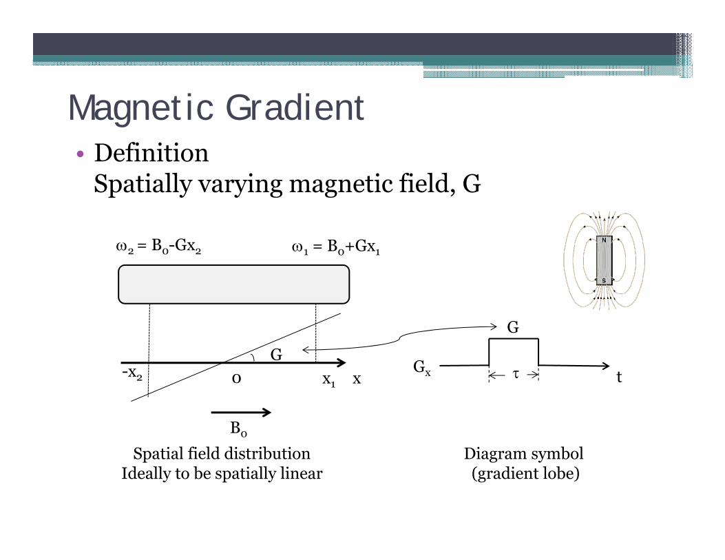
Magnetic Gradient• Definition
Spatially varying magnetic field, G
x
B0
x1
1 = B0+Gx1
0-x2
2 = B0-Gx2
Gt
G
Spatial field distributionIdeally to be spatially linear
Diagram symbol (gradient lobe)
Gx

Generating Gradient pulse
Patent US8269499

Gradient pulse properties• Arbitrary lobe shape, slew rate and Gmax limited by
hardware• Field variation should
be spatially linear at any time

Gradient pulse properties• Directionality• Affects only the Mxy by itself alone• Can affect M in any state when used with RF pulse• Linearly addable (save time): no RF or readouts between
tX
=
tX X=
t
X
RF
≠RF
X tt
Z
Y
X
=
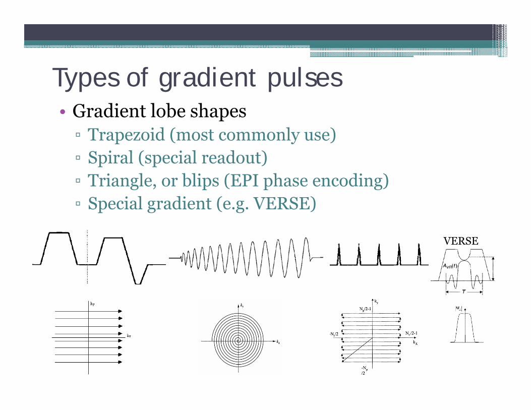
Types of gradient pulses• Gradient lobe shapes▫ Trapezoid (most commonly use)▫ Spiral (special readout)▫ Triangle, or blips (EPI phase encoding)▫ Special gradient (e.g. VERSE)
VERSE

Gradient categories
• Functionality▫ Readout/ Phase encoding/ Slice selection▫ Pre-phase/ Dephase / Rephase▫ Spoiler / Crusher /field compensation (e.g. z-
shimming)
• Imaging contrast related gradients▫ Flow compensation/encoding/dephasing▫ Diffusion gradients▫ etc
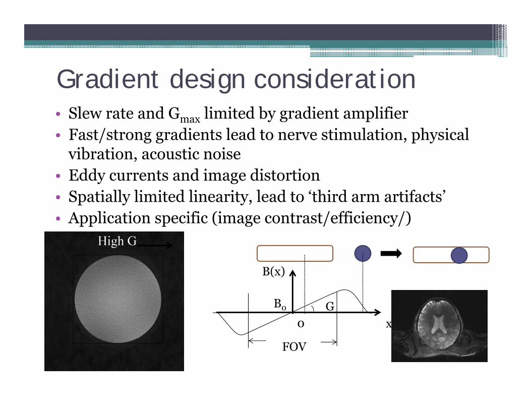
Gradient design consideration• Slew rate and Gmax limited by gradient amplifier• Fast/strong gradients lead to nerve stimulation, physical
vibration, acoustic noise • Eddy currents and image distortion • Spatially limited linearity, lead to ‘third arm artifacts’• Application specific (image contrast/efficiency/)
x
B(x)
B0
0G
FOV

Slice (slab) select gradient• Translate spectral selectivity of the RF pulse to spatial selectivity• Used for excitation, SE refocusing, IR• 0th moment (of the SS part) must be 0 before ADC turns on

Phase encoding gradient• Represented as PE table in seq diagram• PE reordering (ascending, center-out, etc),
effects and restriction• Affects minimal TE
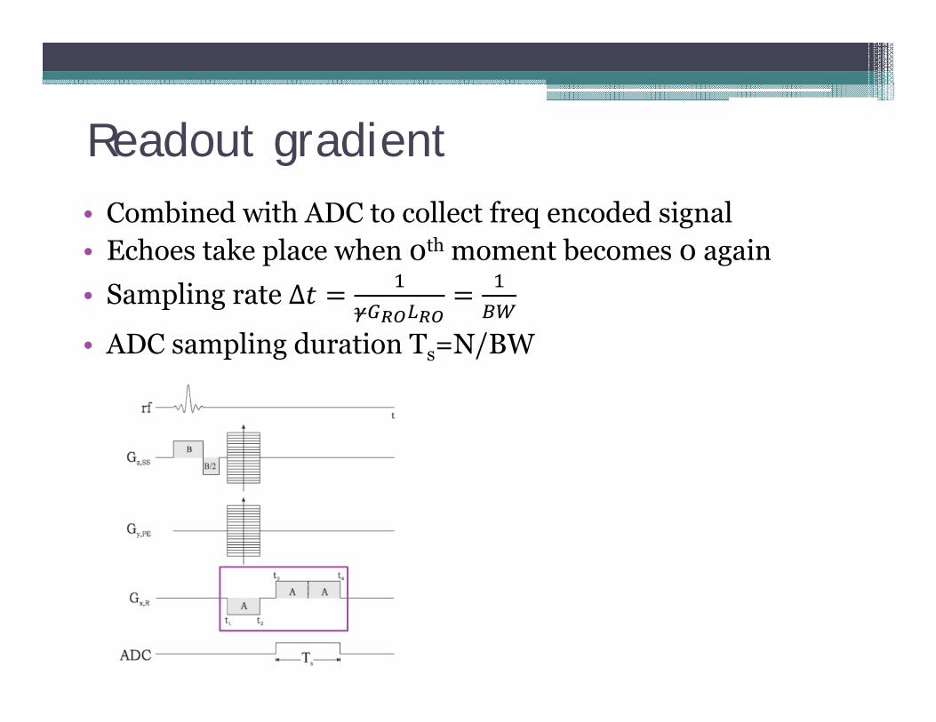
Readout gradient• Combined with ADC to collect freq encoded signal• Echoes take place when 0th moment becomes 0 again• Sampling rate ∆
• ADC sampling duration Ts=N/BW

Sounds of MRI
RARE (Fast Spin Echo)3D GRE GRE-EPI
Just for fun
Practical consideration of MR sequence programming
• Before the programming▫ Know the exact goal and major restrictions & potential
problems ▫ Draft up the sequence diagram
• During programming (apart from the inevitable coding works)▫ Timing; Timing; Timing▫ Consistency/interaction between parameters▫ Simulation and thorough checking on everything
• Debugging & optimization▫ Testing and use deduction to find the cause of problems
(artifact, execution failure, etc)▫ Optimize sequence design and imaging parameters

Imaging parameter dependence (revisit)
/ ∝∆ ∆ ∆
x
Nx
y, z(TH)
Ny, Nz
Gx
Lx
BW/pxBWread Ts
t ProportionalInv. Proportional
TR
Total imaging time TT
Nacq
S
User input para
Implicit para
Outcomes
Ly, Lz
T
TE T1

Sequence examples
2D Spin Echo3D GRE
(Berstein, et al. 2004)Hmmm, something’s not practically right

Sequence examples
RARE (Fast Spin Echo)(Berstein, et al. 2004)
Fig. 26.13
1. What is the practical error in this diagram?
2. CPMG RF phase alternation scheme needed (90x/180y/180y/180y…)
3. Consideration: pulse not strictly
Stimulated echo

Sequence examples
GRE-EPISE-EPI
(Berstein, et al. 2004)
SPSP pulse

Sequence examples
ASL (Konstandin et al, 2009)
DTI with S-T diffusion gradients
Double IR for black blood imaging(Ridgway, JCMR, 2010)

Sequence examples
(Ridgway, JCMR, 2010)
Same sequenceDifferent parameters
Different image contrast

Artifacts (or Artefacts)• A simple object (such as a tool or weapon) that was made by people in the past• An accidental effect that causes incorrect results
Webster Dictionary

ArtifactsAn image artifact is any feature which appears in an image which is not present in the original imaged object.
- Joseph P. Hornak
Bright line artifact/Chemical shift/crossover/DC artifact/distortion artifact/flow artifact/ghosting/ line artifact/misregistration/motion artifact/ blurring/ Gibb’s ringing (truncation) /starring artifact/ streamlining artifact/ susceptibility artifact/ zebra stripe (phase aliasing)/ zipper artifact/spikes artifact…
(Above appeared in the Green Book)
But there are still many more out there…
Magic angle artifact/data clipping/ T2 shine through/ Partial volume/ inflow/outflow/ FOV wrapping/ third arm artifact/ RF interference…
And carelessness artifacts

Source of artifacts
• Hardware/electronic components• Environmental effects• Physiological effects (heart beat, respiration,
motion, blood flow…)• Implants or hygiene • Operational error• Protocol settings/Sequence design/ signal
processing • Mysterious sources

How to treat Artifacts• Artifacts are inevitable, some being significant while others
subtle, but most artifacts can be removed or alleviated or identified
• Apart from ruining the images, artifacts can actually be useful▫ As ‘symptoms’ for diagnosis of the underlying source▫ Forming new contrast mechanism: DWI, BOLD, PCFQ▫ Maybe bad for some sequence but good for others▫ They can be used for fun in some rare cases
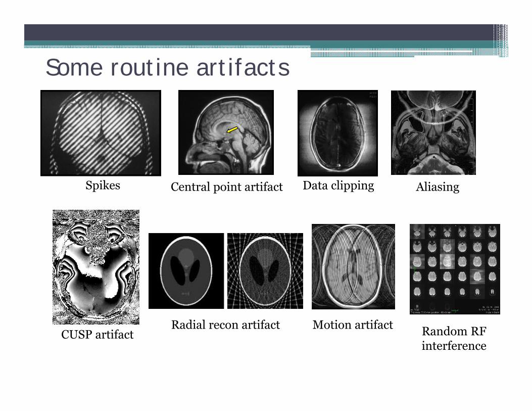
Some routine artifacts
Spikes Central point artifact Data clipping Aliasing
CUSP artifactRadial recon artifact Motion artifact Random RF
interference

Some subtle artifacts
T2 shrine through in DWI Venous contamination in CEMRA
Parallel recon, g-factor
Chemical shift
FatSatpower leakage

My artifact collections
Dielectric effects Unsettled liquid
Double echounbalanced gradients
Zipper (RF) artifactEddy currentfrom Nav
Eddy current+ unsettled liquid
Signal pathway interference in TSE
Possible randomRF interference
Temporally varying artifact
1st 2nd

HomeworkTry to find out the cause and solution for several types of MRI artifacts
Review on SNR, resolution, imaging parameters and image contrast. (Mainly Chaps 15-20)Q & A discussion
Next Session


