72
Chapter 3 Excavating and Lifting Part 1
| Date post: | 23-Dec-2015 |
| Category: |
Documents |
| Upload: | rebecca-wood |
| View: | 358 times |
| Download: | 14 times |
Chapter 3Excavating and Lifting
Part 1
3-1 INTRODUCTION
• Excavating and Lifting Equipment• Excavators and Crane-Shovels• Excavator Production
Excavating and Lifting Equipment
• An excavator is defined as a power-driven digging machine.
• The major types of excavators used in earthmoving operations include – hydraulic excavators and – the members of the cable-operated crane-
shovel family (shovels, draglines, hoes, and clamshells).
– Dozers, loaders, and scrapers can also serve as excavators.
Excavating and Lifting Equipment
• In this chapter we focus on – hydraulic excavators and – the members of the crane-shovel family used
for excavating and lifting operations. • Operations involving the dozer, loader, and
scraper are described in Chapter 4. • Special considerations involved in rock
excavation are discussed in Chapter 8.
Excavators and Crane-Shovels
• In 1836, William S. Otis developed a machine that mechanically duplicated the motion of a worker digging with a hand shovel.
• From this machine evolved a family of cable-operated construction machines known as the crane shovel.
Excavators and Crane-Shovels
• Members of this family include:– the shovel, – backhoe, – dragline, – clamshell, – mobile crane, and – pile driver.
Excavators and Crane-Shovels
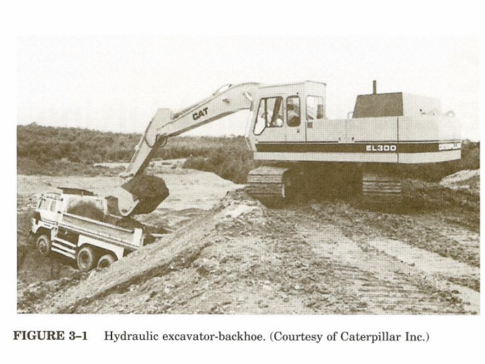
• While hydraulic excavators (Figure 3-1) have largely replaced the cable-operated crane-shovel family, functionally similar hydraulic machines are available including the front shovel and backhoe.
• Attachments available for the hydraulic excavator include clamshells, augers, compactors, and hammers.
Excavators and Crane-Shovels
• The advantages of hydraulic excavators over cable-operated machines are:– faster cycle time, – higher bucket penetrating force, – more precise digging, and – easier operator control.
Excavators and Crane-Shovels
• Hydraulic telescoping-boom mobile cranes are also available.
• The major remaining cable-operated machines based on the original crane-shovel are the dragline and the mobile lattice-boom crane
• Some of many attachments for the hydraulic excavator and their uses include:– Page 42-43
Excavators and Crane-Shovels
• Excavators and crane-shovels consist of three major assemblies: – a carrier or mounting, – a revolving superstructure containing the
power and – control units (also called the revolving deck or
turntable), and – a front-end assembly.

Excavators and Crane-Shovels
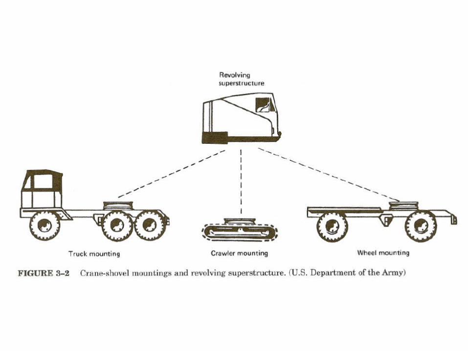
• Carriers available include:– crawler, – truck, and – wheel mountings, as shown in Figure 3-2.
Excavators and Crane-Shovels
• The crawler mounting – provides excellent on-site mobility and its low
ground pressure enables it to operate in areas of low trafficability.
– Crawler mountings are widely used for drainage and trenching work as well as for rock excavation.
Excavators and Crane-Shovels
• Truck and wheel mountings – provide greater mobility between job sites but
are less stable than crawler mountings and require better surfaces over which to operate.
– Truck mountings use a modified truck chassis as a carrier and thus have separate stations for operating the carrier and the revolving superstructure.
Excavators and Crane-Shovels
– Wheel mountings, on the other hand, use a single operator's station to control both the carrier and the excavating mechanism.
– Truck mountings are capable of highway travel of 50 mi/h (80 km/h) or more, whereas wheel mountings are usually limited to 30 mi/h (48 km/h) or less.
Excavators and Crane-Shovels
• In this chapter we discuss:– the principles of operation, – methods of employment, and – techniques for estimating the production of
• shovels, backhoes, clamshells, and draglines.
– Cranes and their employment are also discussed.
– Pile drivers and their employment are covered in Chapter 10.
Excavator Production
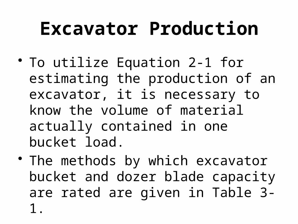
• To utilize Equation 2-1 for estimating the production of an excavator, it is necessary to know the volume of material actually contained in one bucket load.
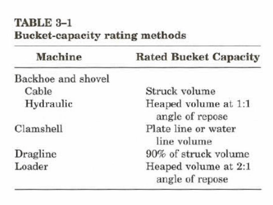
• The methods by which excavator bucket and dozer blade capacity are rated are given in Table 3-1.

Excavator Production
• Plate line capacity is the bucket volume contained within the bucket when following the outline of the bucket sides.
• Struck capacity is the bucket capacity when the load is struck off flush with the bucket sides.
Excavator Production
• Water line capacity assumes a level of material flush with the lowest edge of the bucket (i.e., the material level corresponds to the water level that would result if the bucket were filled with water).
• Heaped volume is the maximum volume that can be placed in the bucket without spillage based on a specified angle of repose for the material in the bucket.
Excavator Production
• Since bucket ratings for the cable shovel, dragline, and cable backhoe are based on struck volume, it is often assumed that the heaping of the buckets will compensate for the swell of the soil.
Excavator Production
• That is, a 5-cu yd bucket would be assumed to actually hold 5 bank cu yd of material.
• A better estimate of the volume of material in one bucket load will be obtained if the nominal bucket volume is multiplied by a bucket fill factor or bucket efficiency factor.
Excavator Production
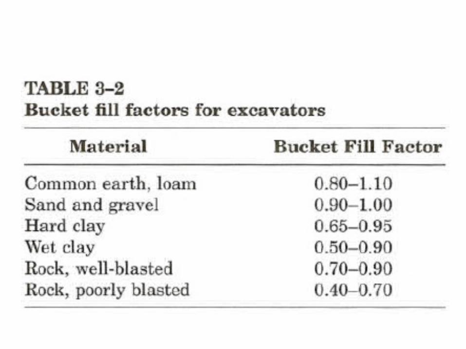
• Suggested values of bucket fill factor for common soils are given in Table 3-2.
• The most accurate estimate of bucket load is obtained by multiplying the heaped bucket volume (loose measure) by the bucket fill factor.
Excavator Production
• If desired, the bucket load may be converted to bank volume by multiplying its loose volume by the soil's load factor.
• This procedure is illustrated in Example 3-1.

EXAMPLE 3-1
Estimate the actual bucket load in bank cubic yards for a loader bucket Whose heaped capacity is 5 cu yd (3.82 m3).The soil's bucket fill factor is 0.90 and its load factor is 0.80.
Solution
Bucket load = 5 × 0.90 = 4.5 LCY × 0.80
= 3.6 BCY
[= 3.82 × 0.90 = 3.44 LCM × 0.80
= 2.75 BCM]
3-2 HYDRAULIC EXCAVATORS
• Operation and Employment• Production Estimating• Job Management
Operation and Employment
• The original and most common from hydraulically powered excavator is the hydraulic excavator equipped with a hoe front end.
• This machine is also called a hydraulic hoe or hydraulic excavator-backhoe.
• A backhoe (or simply hoe) is an excavator designed primarily for excavation below grade.
Operation and Employment
• It digs by pulling the dipper back toward the machine; hence the name backhoe.
• The backhoe shares the characteristics of positive digging action and precise lateral control with the shovel.
• Cable-operated backhoes exist but are largely being replaced by hydraulic models because of their superior speed and ease of control.
• Backhoe attachments are also available for loaders and tractors.
Operation and Employment
• The components of a hydraulic excavator are illustrated in Figure 3-3.
• In this machine, the boom and dipper arms are raised and lowered by hydraulic cylinders.
• In addition, the dipper is pivoted at the end of the dipper arm so that a wrist-like action is provided.
• When the dipper is filled, the dipper is curled up to reduce spillage, and the boom is raised and swung to the unloading position.
• The load is then dumped by swinging the dipper up and away from the machine.
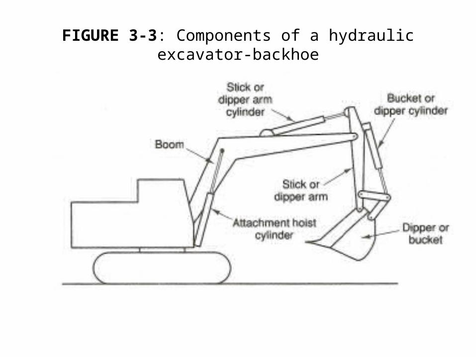
FIGURE 3-3: Components of a hydraulic excavator-backhoe
Operation and Employment• The backhoe is:
– widely utilized for trenching work. – In addition to excavating the trench, – it can perform many other trenching functions,
such as laying pipe bedding, placing pipe, pulling trench shields, and backfilling the trench.
• In trench excavation the best measure of production is the length of trench excavated per unit of time.
Operation and Employment
• Therefore, a dipper width should be chosen which matches the required trench width as closely as possible.
• For this reason, dippers are available in a wide range of sizes and widths.
• Side cutters are also available to increase the cutting width of dippers.
• Other suitable backhoe applications include:– excavating basements, – cleaning roadside ditches, and – grading embankments.
Operation and Employment
• A special form of hydraulic excavator which utilizes a rigid telescoping boom in place of the boom and dipper arm of a conventional hydraulic backhoe is shown in Figure 3-4.
• Due to their telescoping boom and pivoting bucket, these machines are very versatile and capable of:– ditching, – sloping, – finishing, – cleaning ditches, – ripping, and – demolishing as well as trenching.
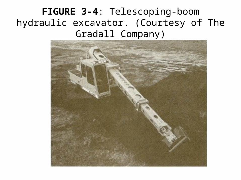
FIGURE 3-4: Telescoping-boom hydraulic excavator. (Courtesy of The Gradall Company)
Operation and Employment
• The use of compact or “mini” excavating equipment is a growing trend in the construction equipment industry.
• Such equipment includes the skid steer loader and the compact loader described in section 4-3 as well as hydraulically powered mini-excavators.
Operation and Employment
• The advantages of such equipment include:– compact size, – hydraulic power, – light weight, – maneuverability, and – versatility.
• A typical mini-excavator is illustrated in Figure 3-5.
• These machines are available in sizes from 10 to 60 hp (7.5-45 kw) with digging depths from about 7 to 15 ft (2.1-4.6 m).
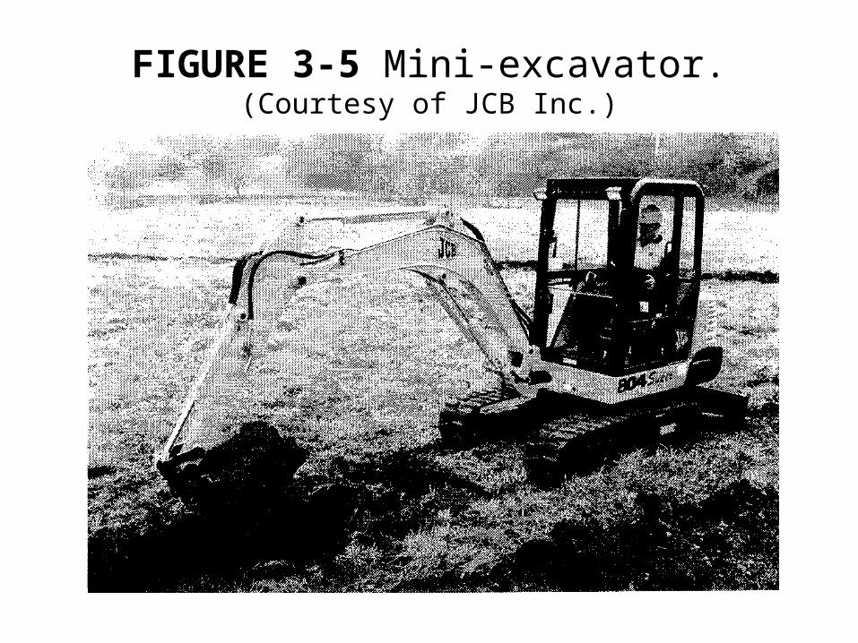
FIGURE 3-5 Mini-excavator.(Courtesy of JCB Inc.)
Operation and Employment
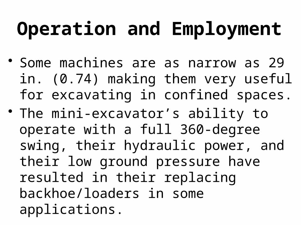
• Some machines are as narrow as 29 in. (0.74) making them very useful for excavating in confined spaces.
• The mini-excavator’s ability to operate with a full 360-degree swing, their hydraulic power, and their low ground pressure have resulted in their replacing backhoe/loaders in some applications.
Operation and Employment
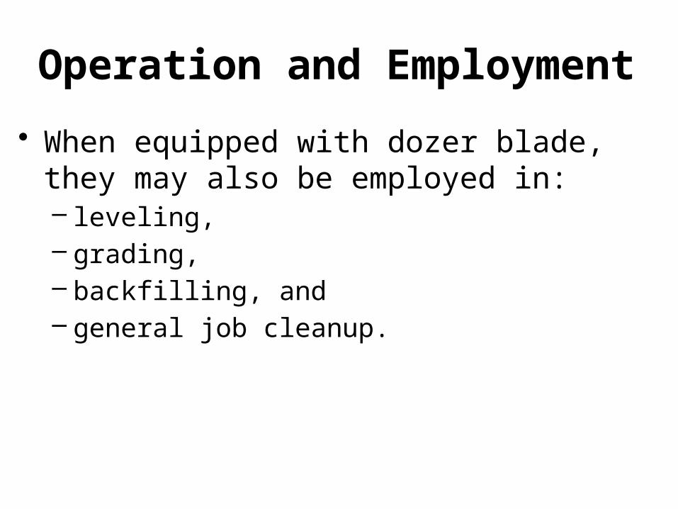
• When equipped with dozer blade, they may also be employed in:– leveling, – grading, – backfilling, and – general job cleanup.
Production Estimating
• No production tables have been prepared for the backhoe.
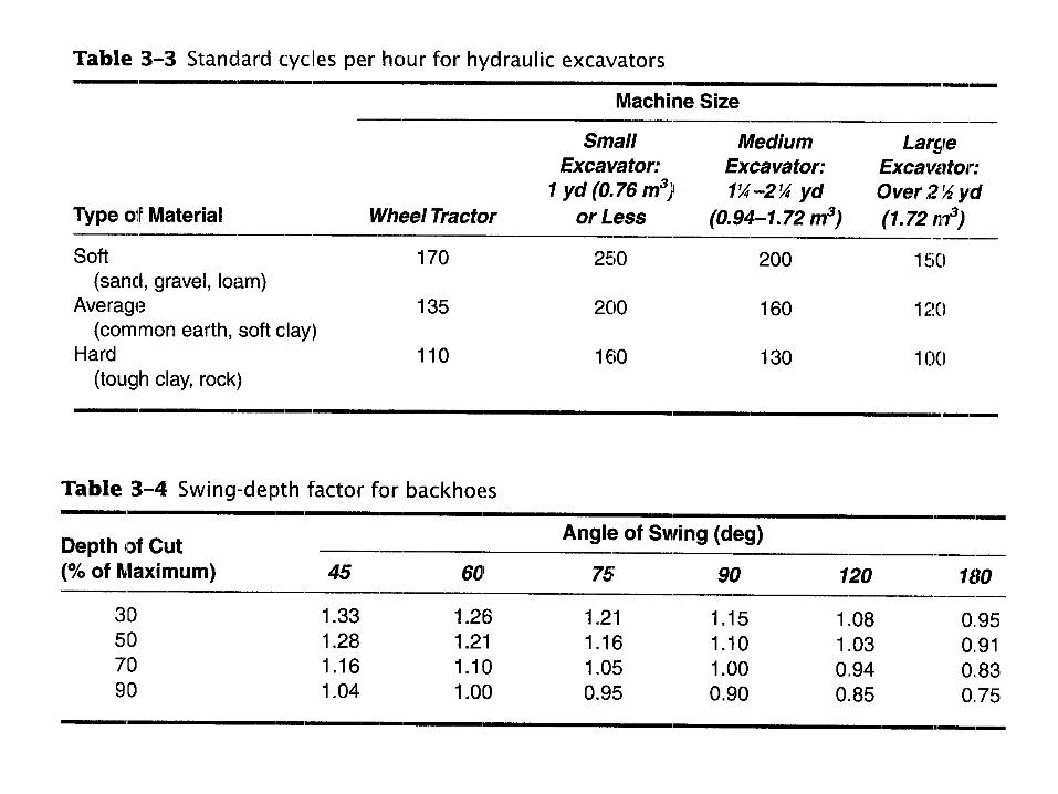
• However, production may be estimated by using Equation 3-1 together with Tables 3-3 and 3-4 which have been prepared from manufacturers' data.
Production Estimating
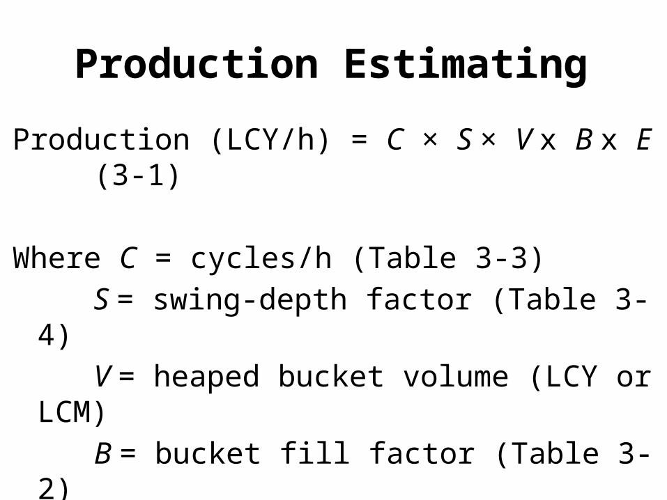
Production (LCY/h) = C × S × V x B x E (3-1)
Where C = cycles/h (Table 3-3)
S = swing-depth factor (Table 3-4)
V = heaped bucket volume (LCY or LCM)
B = bucket fill factor (Table 3-2)
E = job efficiency
3-2 HYDRAULIC EXCAVATORS
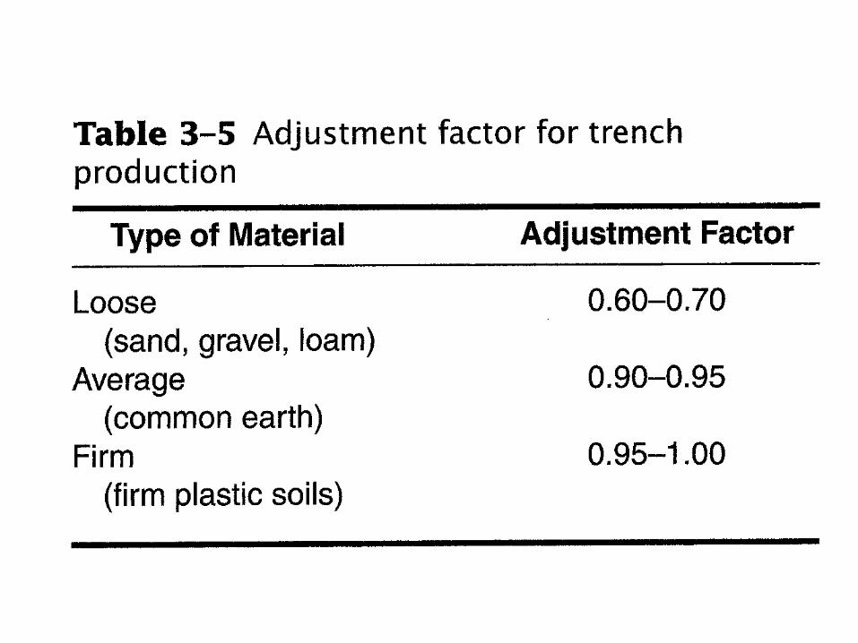
• In trenching work a fall-in factor should be applied to excavator production to account for the work required to clean out material that falls back into the trench from the trench walls.
• Normal excavator production should be multiplied by the appropriate value from Table 3-5 to obtain the effective trench production.
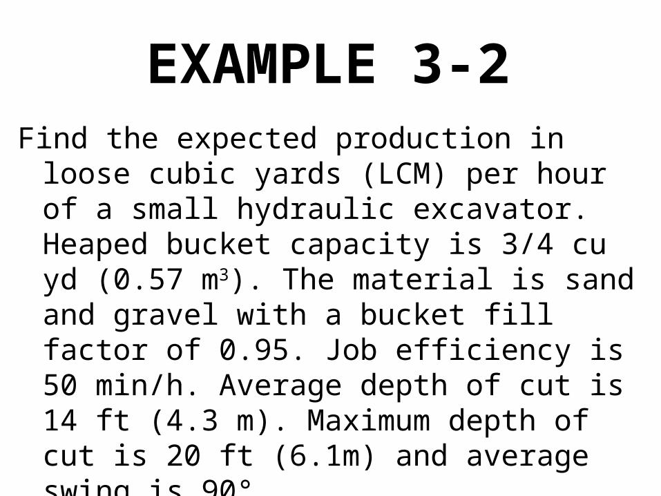
EXAMPLE 3-2Find the expected production in loose cubic
yards (LCM) per hour of a small hydraulic excavator. Heaped bucket capacity is 3/4 cu yd (0.57 m3). The material is sand and gravel with a bucket fill factor of 0.95. Job efficiency is 50 min/h. Average depth of cut is 14 ft (4.3 m). Maximum depth of cut is 20 ft (6.1m) and average swing is 90°.
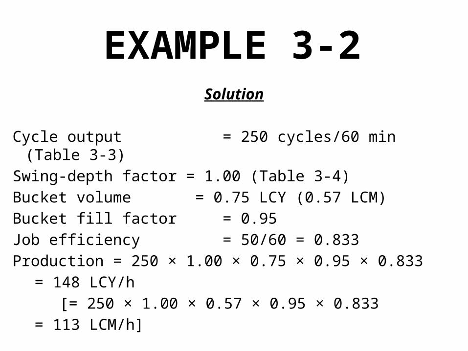
EXAMPLE 3-2Solution
Cycle output = 250 cycles/60 min (Table 3-3)
Swing-depth factor = 1.00 (Table 3-4)
Bucket volume = 0.75 LCY (0.57 LCM)
Bucket fill factor = 0.95
Job efficiency = 50/60 = 0.833
Production = 250 × 1.00 × 0.75 × 0.95 × 0.833
= 148 LCY/h
[= 250 × 1.00 × 0.57 × 0.95 × 0.833
= 113 LCM/h]
Job Management
• In selecting the proper backhoe for a project, consideration must be given to the :– maximum depth, – working radius, and – dumping height required.
• Check also for adequate clearance for the carrier, superstructure, and boom during operation.
Job Management
• Although the backhoe will excavate fairly hard material, do not use the bucket as a sledge in attempting to fracture rock.
• Light blasting, ripping, or use of a power hammer may be necessary to loosen rock sufficiently for excavation.
• When lifting pipe into place do not exceed load given in the manufacturer's safe capacity chart for the situation.

3-3 SHOVELS
• Operation and Employment• Production Estimating• Job Management
Operation and Employment
• The hydraulic shovel illustrated in Figure 3-6 is also called a front shovel or hydraulic excavator-front shovel.
• Its major components are identified in Figure 3-7.
• The hydraulic shovel digs with a combination of crowding force and breakout (or prying) force as illustrated in Figure 3-8.
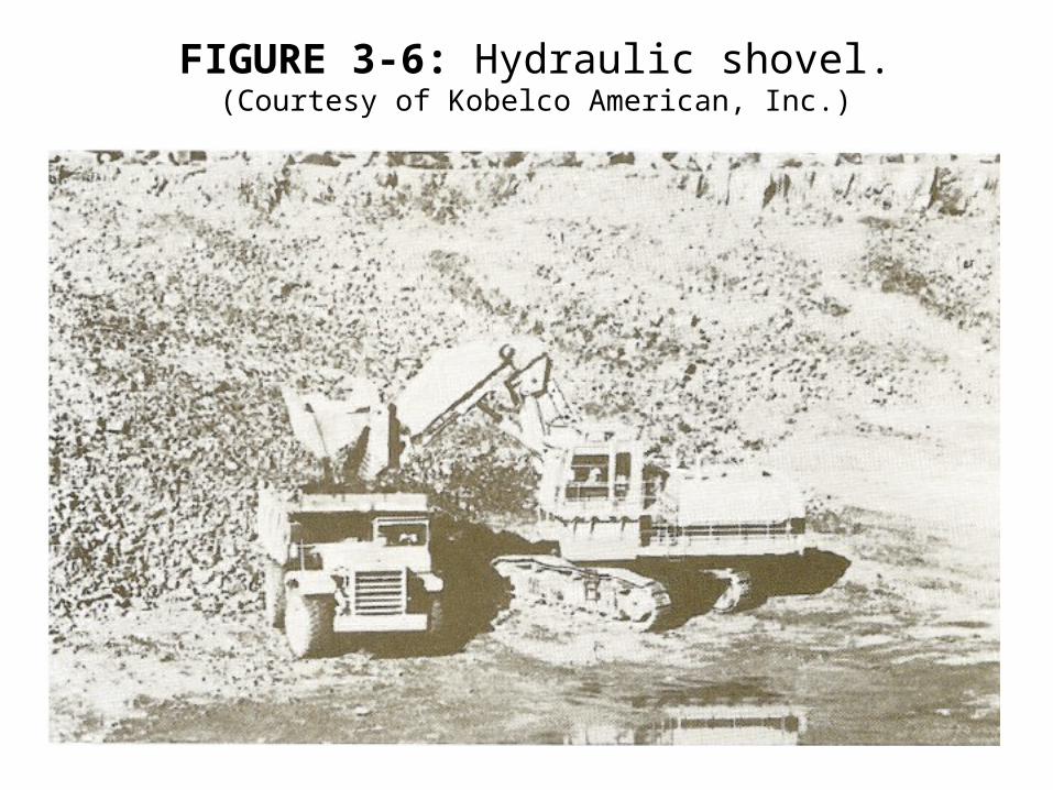
FIGURE 3-6: Hydraulic shovel.(Courtesy of Kobelco American, Inc.)
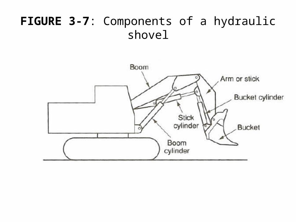
FIGURE 3-7: Components of a hydraulic shovel
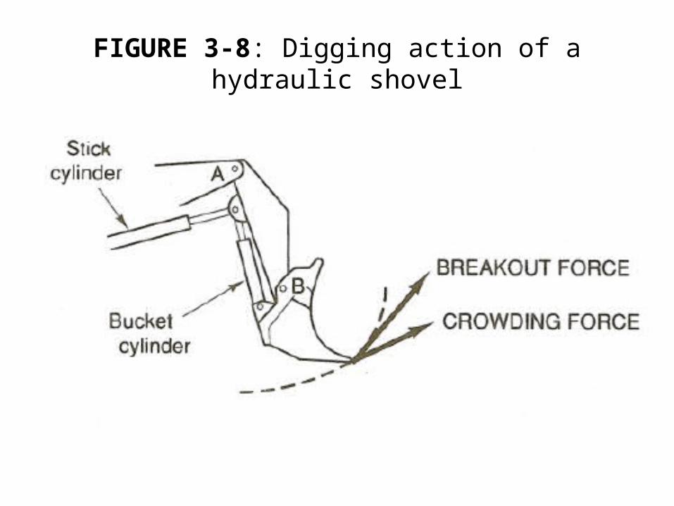
FIGURE 3-8: Digging action of a hydraulic shovel
Operation and Employment
• Crowding force is generated by the stick cylinder and acts at the bucket edge on a tangent to the arc of the radius from point A.
• Breakout force is generated by the bucket cylinder and acts at the bucket edge on a tangent to the arc of the radius through point B.
• After the bucket has penetrated and filled with material, it is rolled up to reduce spillage during the swing cycle.
Operation and Employment
• Both front-dump and bottom-dump buckets are available for hydraulic shovels.
• Bottom-dump buckets are:– more versatile, – provide greater reach and dump clearance, and – produce less spillage.
• Bottom-dump buckets are heavier than front-dump buckets of equal capacity,– resulting in a lower bucket capacity for equal
bucket weight.
Operation and Employment
• Hence front-dump buckets usually have a slight production advantage.
• In addition, front-dump buckets cost less and require less maintenance.
• Although the shovel has a limited ability to dig below track level, it is most efficient when digging above track level.
Operation and Employment
• The shovel should have a vertical face to dig against for most effective digging.
• This surface, known as the digging face, is easily formed when excavating a bank or hillside.
• Thus embankment digging with the material dumped to one side (sidecast) or loaded into haul units provides the best application of the shovel.
• The ability of the shovel to form its own roadway as it advances - an important advantage.
Operation and Employment
• The shovel is also able to shape the sides of its cut and dress slopes when required.
• Material dug by the shovel can be loaded into haul units, dumping onto spoil banks, or sidecast into areas.
• The shovel should have a vertical face to dig against for most effective digging.
• This surface, known as digging face, is easily formed when excavating a bank of hillside.
Operation and Employment
• When the material to be excavated is located below ground level, the shovel must dig a ramp down into the material until a digging face of suitable height is created.
• This process is known as ramping down.• Once a suitable digging face has been
obtained, the cut is typically developed by using one of two basic methods of attack (or a variation of these) illustrated in Figure 3-9.
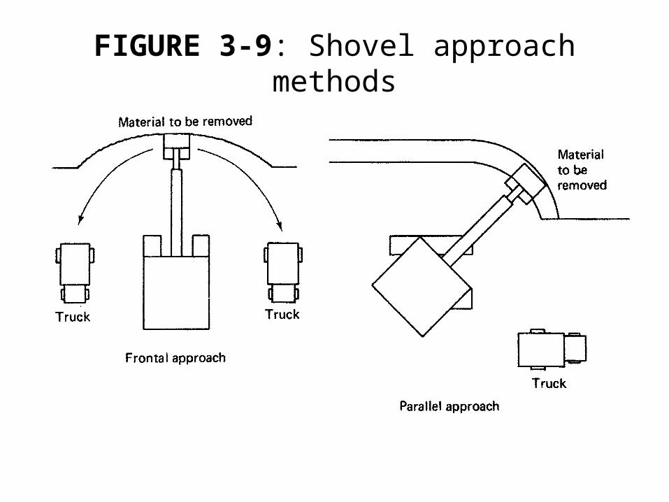
FIGURE 3-9: Shovel approach methods
Operation and Employment
• The frontal approach allows the most effective digging position of the shovel to be used since the shovel can exert the greatest digging force in this position.
• This is an important consideration in digging hard materials.
Operation and Employment
• Trucks can be located on either or both sides of shovel with a minimum swing, usually no greater than 90o.
• The parallel approach permits fast move-up of the shovel as the digging face advances, and it permits a good traffic flow for hauling units.
• This approach is often used for highway cuts and whenever space is limited.
Production Estimating
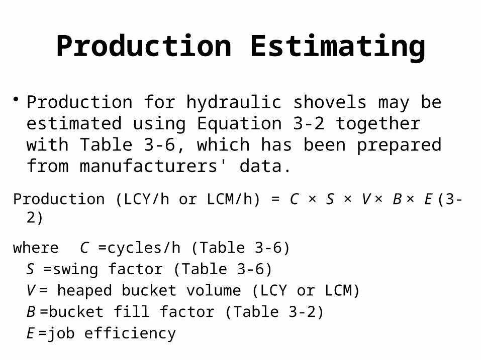
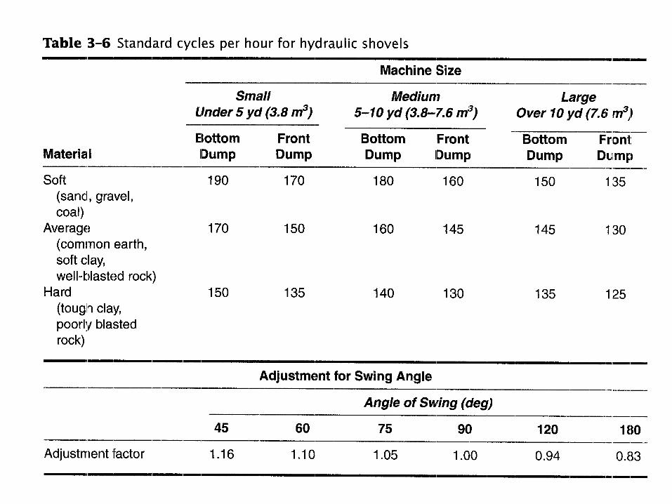
• Production for hydraulic shovels may be estimated using Equation 3-2 together with Table 3-6, which has been prepared from manufacturers' data.
Production (LCY/h or LCM/h) = C × S × V × B × E (3-2)
where C =cycles/h (Table 3-6)
S =swing factor (Table 3-6)
V = heaped bucket volume (LCY or LCM)
B =bucket fill factor (Table 3-2)
E =job efficiency
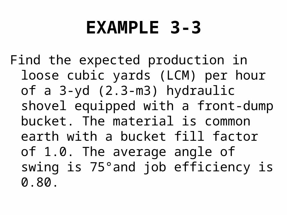
EXAMPLE 3-3
Find the expected production in loose cubic yards (LCM) per hour of a 3-yd (2.3-m3) hydraulic shovel equipped with a front-dump bucket. The material is common earth with a bucket fill factor of 1.0. The average angle of swing is 75°and job efficiency is 0.80.
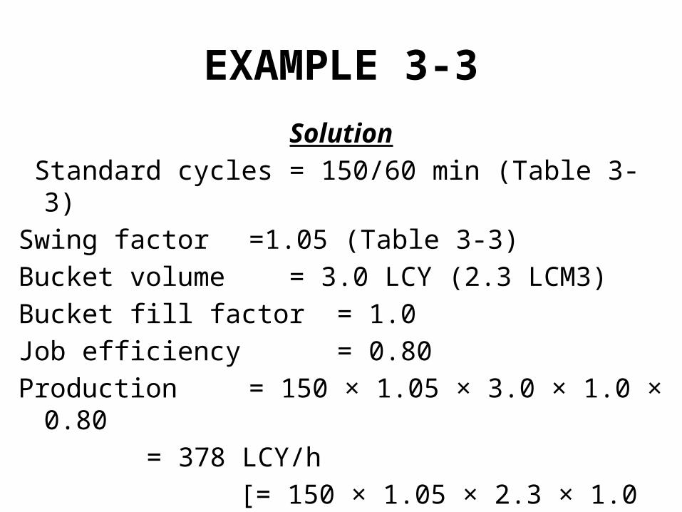
EXAMPLE 3-3
Solution
Standard cycles = 150/60 min (Table 3-3)
Swing factor =1.05 (Table 3-3)
Bucket volume = 3.0 LCY (2.3 LCM3)
Bucket fill factor = 1.0
Job efficiency = 0.80
Production = 150 × 1.05 × 3.0 × 1.0 × 0.80
= 378 LCY/h
[= 150 × 1.05 × 2.3 × 1.0 × 0.80
= 290 LCM/h]

Operation and Employment
• For cable-operated shovels, the PCSA Bureau of CIMA has developed production tables that are widely used by the construction industry.
Job Management• The two major factors controlling shovel
production are the swing angle and lost time during the production cycle.
• Therefore, the angle of swing between digging and dumping positions should always be kept to a minimum.
Job Management• Haul units must be positioned to minimize the
time lost as units enter and leave the loading position.
• When only a single loading position is available, the shovel operator should utilize the time between the departure of one haul unit and the arrival of the next to move up to the digging face and to smooth the excavation area.
Job Management• The floor of the cut should be kept smooth to
provide an even footing for the shovel and to facilitate movement in the cut area.
• The shovel should be moved up frequently to keep it at an optimum distance from the working face. Keeping dipper teeth sharp will also increase production.


