Page 1
90
CHAPTER 3
GROWTH OF ANTHRACENE, NAPHTHALENE AND
DOPED NAPHTHALENE CRYSTALS AND THEIR XRD,
UV-VISIBLE, RAMAN STUDIES
3.1 INTRODUCTION
Anthracene and naphthalene crystals are classified as the organic
scintillators. The scintillation counting techniques have found a wide variety
of important applications in biology, chemistry, geology, medicine,
atmospheric science, and industry. Most organic scintillators are either
monocrystalline compounds or liquid or plastic solutions. Among the most
efficient monocrystalline compounds are naphthalene, anthracene,
fluoranthane, p-terphenyl, p-quaterphenyl, and trans-stilbene. In scintillation
detector, a larger light output by suitable doping materials is a welcome
feature. There is the interesting possibility of producing improved organic
crystal scintillators with a reduced decay time and the same or enhanced
scintillation efficiency, by introducing lattice defects which do not quench the
fluorescence but instead facilitate the exciton-photon transformation and
reduce the exciton lifetime. Naphthalene or similar non-absorbing molecules
may function in this manner, in anthracene, for example (Birks 1964).
Literature survey shows that naphthalene has been doped by
number of molecular crystals like anthracene, pyrene (Chabr and
Zschokke-Granacher 1976, Richard Powell 1971, Bowen et al 1949) tetracene
(Reed and Lipsett 1957) pentacene (Duppen et al 1983),
Page 2
91
1,3-phenylenediamine, 1,4-toluidine, 1,3-toluidine, 1,2-toluidine, aniline,
durene, 1,2-nitroaniline, hydroquinone, 1,3-nitroaniline, resorcin, toluene,
1,2-dibromobenzene, 1,2-dichlorobenzene, benzene, p-phenylstilbene,
1,2-di(beta-naphthyl)-ethylene, 1-(beta-naphthyl) 2-(p-byphenyl)-ethylene
(Lagonaya et al 1966), dibenzoterrylene (Jelezko et al 1996). The molecular
structures are given in Figure 3.1.
This chapter mainly focuses on growth of anthracene, naphthalene
(pure and doped) crystals. Naphthalene crystals were doped by anthracene and
2,5-diphenyloxazole (PPO). Scott and Laridjani (1974) described the
acceptability of organic dopant in organic crystals. Naphthalene is the first
organic scintillator (Broser and Kallmann 1947) then anthracene was
introduced as an efficient scintillation material which is five times better than
the naphthalene (Bell 1948). Single crystals of anthracene have the highest
practical scintillation efficiency of any organic scintillator so far reported. For
this reason they are commonly used as comparison standards and many
observations of the practical efficiencies of other materials are expressed
relative to anthracene. The growth of very large crystals is desirable for the
absorption and detection of high energy gamma-rays. However, technically it
is difficult to grow large anthracene crystals for such applications due to
decomposition of the anthracene melt when exposed to atmosphere due to
oxygen. In addition, due to the difference in thermal expansion co-efficient of
anthracene & container the grown crystals are highly defective. Naphthalene
can be grown in larger crystals, several inches in diameter, by controlled slow
freezing from the melt. The fluorescence emission is on the edge of phototube
spectral response (Birks 1950). Because of very low solubility nature
(Madhurambal and Anbu Srinivasan 2006) it is very difficult to grow bigger
crystals from solution growth. The anthracene fluorescence emission is well
matched with the spectral response of PMTs. The crystal structure of
Page 3
92
1.Anthracene; 2.Tetracene; 3.Toluene; 4.Benzene; 5.Pentacene; 6.1,2-toluidine; 7.1,3-toluidine; 8.1,4-toluidine; 9.Hydroquinone; 10.1,3-phenylenediamine; 11.Aniline; 12.1,2-nitroaniline; 13.Durene; 14. Pyrene; 15.1,3-nitroaniline; 16.Resorcin; 17.1,2-dibromobenzene; 18.1,2-dichlorobenzene; 19.Dibenzoterrylene
Figure 3.1 Molecular structure of some organic materials which are
doped into naphthalene crystals
14
1 2
3 4 5
6 7 8 9
10 11 13 12
15 16
17 18
19 19
Page 4
93
naphthalene and anthracene are virtually identical except for the length of the
unit cell in the c direction. Both crystals are monoclinic and the two
molecules in the unit cell are related by a glide plane perpendicular to the b
axis (Schlosser and Philpott 1980).
PPO is a well known scintillating molecule (Kimberly et al 1995).
Growth of pure PPO is very tough and it grows as milky crystals. It is a major
component of most commercially available scintillation cocktails (Hariharan
et al 1997).
Growth of organic crystals from the vapour phase usually results in
slow growth of very thin crystal (Karl, 1980 Buckley 1951, Lawson and
Neilsen 1958). Thus, when large single crystals are required, these must be
grown from the melt, or from saturated solution. In the case of anthracene and
naphthalene, the latter method is of doubtful applicability, because the
limiting factor in growth from solution is solubility. Solubilities of 20-50 %
by weight are required for tolerable growth rates and size. Anthracene and
naphthalene solubilities are much lower. There is also the disadvantage of
possible solvent occlusion.
The selective self seeding vertical Bridgman technique (SSVBT)
technique was chosen for the present study. The investigation is concerned
with several important criteria to be observed before crystals can be grown
successfully, namely, the purity of materials, the temperature gradient, the
rate of crystal growth, and the shape of the growth vessel. These are of
paramount importance for growing crystals (Marciniak and Waclawek 1981).
The lower melting point of the organic crystals often offers the
advantage that transparent glass-made growth apparatuses can be used, in
which the growth process can be easily followed by direct observation. There
Page 5
94
are many uses for transparent furnaces in materials processing and fluid and
solid mechanics at elevated temperatures. Transparent furnaces can be used
for research in crystal growth, sintering, metal joining, and annealing, high
temperature materials properties, and the behavior of flowing systems that use
high temperature liquids. In the area of crystal growth, some of the
capabilities introduced by a transparent furnace are: 1) Nucleation can be
observed; if multiple nucleation sites occur solidification can be restarted,
2) The melt/solid interface can be viewed as a result of differences in density
and emissivity between the liquid and solid, 3) Surface tension effects can be
studied as a result of these liquid-solid differences, 4) Convection can be
studied through index of refraction changes with temperature, 5) Internal
temperatures can be monitored by tomographic means, and 6) A variety of
crystal defects are visible, depending on the optical properties of the crystal
(Stephen et al 1997).
3.2 CONSTRUCTION OF FURNACE
A glass tube was used for Bridgman furnace; the furnace separated
into two zones, each 30 cm long. Each zone was wound with thin A1 Kanthal
of thickness 0.5 mm having total resistance of 50 ohms. For winding, ceramic
thread has been used for grip in the glass material. The space between the
winding was kept as 2 mm. The setup was enclosed by a concentric
borosilicate glass tube, which ensured the thermal insulation. The schematic
diagram of the vertical growth furnace with translation setup is shown in
Figure 3.2.
Page 6
95
Pulleys
Cotton Thread
Inner glass tube
Kanthal wire Outer glass tube
Double wall ampoule
Kanthal wire winding
12 V DC power supply
Conical screw type rod
Figure 3.2 Schematic diagram of the transparent Bridgman-
Stockbarger setup
The setup has been enclosed by a black envelope to provide light
shielding for the material during growth because of photo plastic nature
(Kojima 1981) and dimerisation of the grown crystals is possible due to UV-
Visible light exposure at high temperatures. The growth furnace was placed
on the wooden stool whose bases are supported by vinyl sheets to avoid
vibration and the stool was leveled using spirit level so that the furnace had no
asymmetric tilt. With this arrangement and by virtue of the heavy weight of
the furnace itself mechanical vibration was practically eliminated. The
temperature of the furnace was controlled by programmable Eurotherm PID
controllers. The photograph of the two zone glass furnace is shown in
Figure 3.3.
Page 7
96
Figure 3.3 Photograph of the transparent two zone furnace
3.3 TRANSLATION SETUP
Because there is no forced convection in the melt during Bridgman
growth, a slower growth rate should be used to grow the crystals with higher
quality. The rate of crystal growth sets an upper limit to the rate at which the
crystal-growing vessel can be lowered in the oven. A rate of 1-2 mm/h has
been recommended as an upper limit for organic crystals, in contrast to
20 mm/min for metals and 1-4 mm/h for ionic crystals (Sherwood 1960). The
larger diameter crystals should be grown by even slower growth rate.
However the reports proposed a constant growth rate for full growth of
Page 8
97
crystals. But the organic crystals are of low thermal conductivity. So, if the
diameter of the ampoule increases the translation rate must be reduced.
A translation assembly has been developed using a DC motor with
multistage gear setup. A conical screw type mechanism (Figure 3.2) was used
to translate the ampoule. The screw was fixed to the end of the gear setup.
One end of a Teflon thread was rolled in the conical type screw and the other
end was fixed on the ampoule via metal wire and two pulleys. The thread was
rolled towards the bigger diameter form the end of the screw. A 2 cm long
cylindrical rod has been fixed at the end of the conical screw. When the
DC motor rotates with a constant speed, the translation smoothly decreases as
the diameter of the screw decreases then the translation was at a constant rate.
3.4 TEMPERATURE PROFILE STUDY
The temperature profile studies were carried out using a
programmable temperature-time data logging system as described in previous
Chapter. The Figure 3.4 shows the on-line temperature profile for the
transparent two zone furnace with the setting points of 220oC (I-zone) and
200 oC (II-zone).
3.5 GROWTH CONTAINER (AMPOULE)
The production of good seed crystal is difficult for organic
materials. Different containers have been discussed in respect to organic
crystal by Lipsett (1957), Sherwood and Thomson (1960) and
Arulchakkaravarthi et al (2002a). Though the double walled ampoule growth
was used earlier, the effect of the distance between the inner seeding capillary
Page 9
98
Figure 3.4 Online temperature profile
and the outer tube, which is vital for all time occurrence of the single crystals,
has been done by Arulchakkaravarthi et al (2002a). In the SSVBT method
reported, the double wall ampoule-grown crystals were single crystals for all
the growth runs and the quality of the crystals was better compared to the
conventional growth. The lower end of the inner tube has a capillary of
0.5�1 mm. If the angle of the capillary to the vessel axis is less than 45o the ab
cleavage plane anthracene crystals will grow parallel to the vessel axis, but if
this angle is greater than 45o the ab-cleavage plane will grow perpendicular to
the vessel axis (Sherwood 1960). The substance after melting fills the annular
space between the inner and outer tubes and acts as an insulator to prevent
thermal shocks entering the inner tube during growth. The space above the
melt level also acts as a thermal insulator due to vacuum. The inner wall cone
angle of 20°�24° was helpful to avoid multi twinning and strain induced by
the contraction of the walls of the ampoule. A model ampoule for our growth
is shown in Figure 3.5 which is similar to the SSVBT ampoule used by
Arulchakkaravarthi et al 2002a. The hole was helpful to evacuate the air
between the inner and the outer wall.
Page 10
99
Hole
Figure 3.5 Ampoule design for crystal growth
3.6 PURIFICATION PROCESSES
The commercially purchased material contains impurities. Before
crystal growth the purification is important. In this work the following
purification procedures were involved.
3.6.1 Recrystallisation from Solvent
This process involves identifying a suitable solvent in which the
material to be recrystallised or purified has high solubility at elevated
temperature (typically near the boiling point of the solvent) and low solubility
at low temperature. The solid (or mixture) is dissolved in a minimal volume
of hot solvent, filtered to remove any insoluble components in the mixture
and the solution is slowly cooled to allow the product to crystallise. The
formation and growth of crystals is a complex process that involves the
removal of molecules from solution (molecule by molecule) and stacking
them into a regular condensed state where the molecules are packed in a
Page 11
100
crystal lattice. Like molecules tend to pack more efficiently, so the growth of
crystals tends to bring together molecules of the same type. The effect of
dissolving a solid in a solvent and then permitting it to crystallise is that the
crystals that form contain less impurities than the material that was originally
dissolved. Successive recrystallisations can produce extremely pure
crystalline samples.
3.6.2 Sublimation Purification
A single-zone furnace for sublimation purification was constructed.
The zone is controlled with a temperature controller and K-type
thermocouple. The purification ampoule utilized is 30 cm long and 2 cm in
diameter. The ampoule is sealed with materials under the low pressure
(~10-3-10-6 torr). The device operates by subliming stock material and
transporting molecules to the cooler region, where they are deposited.
Impurities are left in the high temperature region, and volatiles are transported
to the cold trap. The purified material is collected from the middle region.
Generally it takes at least three sublimation runs to complete this stage in the
material purification process.
3.6.3 Zone Refining
The zone refinement process has been used successfully to remove
impurities that are generally not removable by other purification methods.
A furnace designated for zone refinement processing has been designed and
built. The furnace consists of three asbestos cement sheets A, B and C
(Figure 3.6) of thickness 0.5 cm and radius 15 cm. The asbestos cement sheets
A and C have holes at the centre, slightly greater than the diameter of the tube
in which the zone refining is to be carried out. The diameter of the hole in the
central asbestos sheet B is about 2 mm more than that of A and C. The
heating coil is wound on B (Figure 3.6D). An ordinary Kanthal heating
Page 12
101
element is used as a heating coil. The closed electric connections were taken
out through a twin bore ceramic tube. The three asbestos cement sheets along
with the heating coil and thermocouple were fixed by screws and nuts, and
were kept in a stand. This furnace provided temperature of up to 350°C with a
heating zone of about 1.5 cm. A sample to be purified is sealed in an ampoule.
A small, evacuated, and sealed ampoule (filled with material to be purified) is
then pulled upward along the length of the furnace by a motor at a
pre-determined speed. This was repeated many times. The purified materials
were collected and filled in another ampoule. Then the ampoule traversed
downward direction and it repeated many times. Impurities migrate away
from the melted region, which slowly pushes the impurities to the ends of the
entire material sample.
Figure 3.6 Zone refining setup
A
B
C
A E D
Page 13
102
3.7 CRYSTAL GROWTH
3.7.1 Growth of Anthracene Crystals
Robertson (1958) determined the crystal structure of anthracene
and Cruickshank (1956) and later Mason (1964) refined it with a = 8.561 Å,
b = 6.035 Å, c =11.163 Å, beta= 124o , Z = 2, monoclinic, P21/a, M =178.2 g
mol-1 and D = 1.26 Mg m-3 . It has a perfect cleavage plane parallel to <001>
direction. Single crystals of anthracene can be grown from the vapour phase,
from the melt, and from its saturated solutions. Selection of the suitable
method depends upon the melting point, crystal structure, and chemical
properties of the material, as well as on the required shape and size of the
crystals (Karl 1980). The quality of the crystals grown from recrystallized
material was very much better than that of crystals grown from material
purified by chromatography (Sherwood 1960).
Anthracene (>99%) was commercially purchased from Zigma
Aldrich. Since anthracene is derived from coal tar the presence of impurities
like carbazole, phenanthrene, pyrene, fluorine and methyl derivatives of
anthracene are more possible. So the materials have been subjected for
purification by using various techniques. Anthracene was purified from
recrystallisation by various authors from various solvents. A detailed study on
purification of anthracene has been done by McDowell (1908). He used
kerosene, xylol, chloroform and alcohol as solvent for recrystallization. The
purification was done by means of recrystallisation using acetic acid, toluene
and ether by Sherwood and Thomson (1960). But Robinson and Scott (1967)
used ethylene chloride and pentane for purifying the anthracene. Marciniak
and Waclawek (1981) had purified from dimethyl sulphoxide and hexane.
Dimethyl sulphoxide, dimethyl formamide and hexane were used by
Arulchakkaravarthi et al (2002b). Dimethyl sulphoxide and ethonal were used
in the present study. Commercially purchased anthracene was purified by
Page 14
103
fourfold recrystallization using dimethylsulphoxide (DMSO) as the solvent,
which removed carbazole, effectively. Then the recrystallized anthracene was
washed in ethyl alcohol. The recrysallized anthracene was then purified by
sublimation and zone refining.
Finally the zone heating of the substance was done in high vacuum
of about 10-6 Torr, which was obtained by using Hind High Vacuum diffusion
pump. The main aim of the vaccum is the removal of oxygen, otherwise
anthracene will oxidize. The zone refining glass tube was 30 cm long with
diameter of 2 cm. The substance was zone purified for about 30 times in the
upward direction by using above described vertical zone purification
assembly at the rate of 2-1cm/h. The purified material was taken in another
ampoule and it was passed through the zone about 30 times in the downward
direction. The impurity-segregated parts were removed and the pure substance
was taken for growth. The substance melted at 217 oC in a specially designed
double walled ampoule under vacuum (about 10-6 Torr). Vacuum in the
crystal growth tube ensures higher quality crystal since inert gases have been
found to adversely affect crystal quality (Karl 1980). The upper zone
temperature was maintained at 3oC above the melting point using PID
controller with accuracy ± 0.1°. The lower zone was maintained at 150oC. The
temperature sensors were fixed in the middle of each zone. The temperature
profile obtained for this temperature setting is shown in Figure 3.4.
The translation of the melted substance from upper zone to the
lower zone allows directional freezing of the substance from the bottom to the
top of the growth vessel. Initially the translation speed was set to 1 mm/h.
Due to the above described translation mechanism the translation rate was
varied from 1 mm � 0.3 mm/h as the diameter of the ampoule increases and
the translation rate was maintained at 0.3 mm/h in the cylindrical region.
After many attempts the successful growth was achieved by translating the
Page 15
104
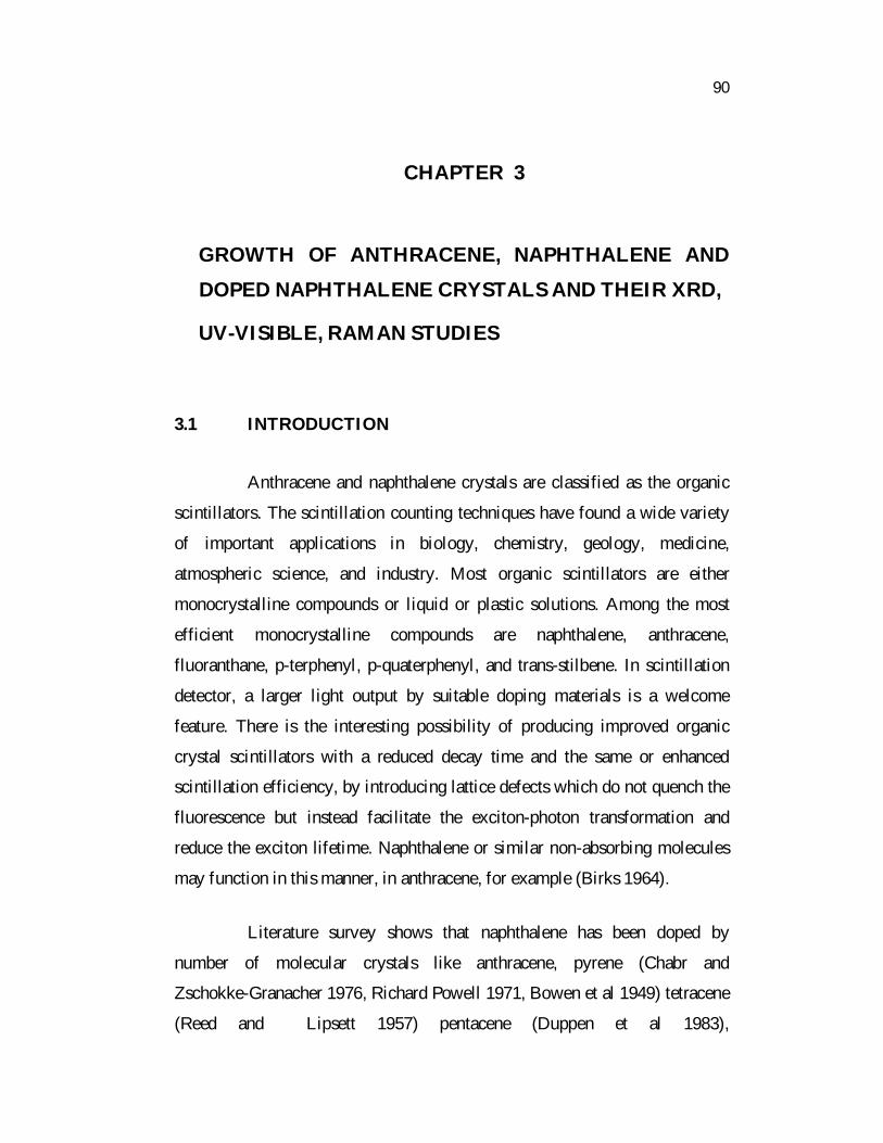
ampoule as stated above. After the completion of full growth the temperature
was decreased step by step from 1-10 oC/h. However, a rate greater than
1.5 mm/hr resulted in the formation of polycrystals. The crystal grown in the
vessel had (001) cleavage plane vertical. The grown crystal with ampoule is
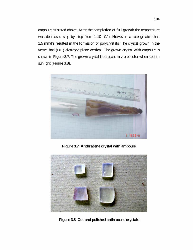
shown in Figure 3.7. The grown crystal fluoresces in violet color when kept in
sunlight (Figure 3.8).
Figure 3.7 Anthracene crystal with ampoule
Figure 3.8 Cut and polished anthracene crystals
Page 16
105
3.7.2 Growth of Naphthalene Crystals
Bragg (1921) determined the crystal structure of naphthalene and
later Cruickshank (1957) refined it with a = 8.235 Å, b = 6.003 Å,
c = 8.658 Å, beta= 123o , Z = 2, monoclinic, P21/a, M =128.2 g mol-1 and
D = 1.162 Mg m-3 .
Naphthalene is a transparent organic compound melting at 80 oC,
which normally freezes with a non-faceted interface (Wilcox 1964) and it also
cleaves readily on the (001) plane like anthracene. Naphthalene does not react
with air (Lipsett 1957) and it has a low vapour pressure (10 kPa) at its melting
point. It can be grown in open ampoule. Due to the sublime nature of
naphthalene, it was grown in a closed ampoule system.
The sublimation of naphthalene was done in a glass tube 30 cm
long and diameter 2 cm using the two zone furnace. The temperature of the
lower part of the tube was maintained at 60 oC and the upper part was around
40oC. In 40 hrs >95 % of the substance was sublimed in upper part. The
middle portion was collected for zone refining process (50 passes).
Double walled selective self seeded ampoule was used to grow
naphthalene crystals. The tube was evacuated to ~10-4 Torr and then sealed
off. The tube was placed in the vertical Bridgman furnace with two
temperature zones, where the temperatures of the upper and lower zones were
kept at 82 oC and at 50 oC, respectively. The corresponding temperature
profile is shown in Figure 3.9.
Many trials were made to optimize the translation rate. The
translation rate was started at a rate of 1 mm/h (to initiate less number of
nucleations) then increased to 3 mm/h and it was decreased to 1 mm/h
Page 17
106
0 20 40 6030
40
50
60
70
80
90
Low er zone
Furnace depth
U pper zone
1.5 oC /cm
Figure 3.9 Temperature profile for naphthalene crystal growth
towards the end of the cone. The translation rate was maintained at 1 mm/h in
the cylindrical region. The grown crystal was free from visible inclusions.
The crystals were grown at different rates of 0.5, 1.5, 2, 2.5 mm/h. However,
as the growth was conducted at a rate more than 2 mm/h, the crystal quality
deteriorates. So the growth rate in the range of 1-2 mm/h is desirable to grow
good quality crystals. When the tip of the tube crossed the interface, the
crystallization of the molten naphthalene was initiated by self-nucleation and
it had (001) cleavage plane vertical. After the crystal growth, the crystals were
slowly cooled down to room temperature at the rate of 1-2 oC/h. Since the
surface of naphthalene crystals deteriorate by sublimation the surface was
preserved by coating them with optical grease. Growth of naphthalene
crystals was easier than anthracene crystals and also it grows faster than
anthracene.
Page 18
107
Figure 3.10 Naphthalene crystal with ampoule
3.7.3 Growth of Anthracene Doped Naphthalene Crystals
Based on literature survey naphthalene crystals with 0.01 mole
anthracene/mole naphthalene have been grown from melt because in this
concentration the naphthalene shows maximum fluorescence efficiency. This
concentration is interesting for scintillation detector because it shifts the
luminescence to higher wavelength, which matches the spectral sensitivity of
most of the phototube without much change in luminescence efficiency.
Zone purified naphthalene sample was carefully powdered and
mixed with 0.01 mole of anthracene/mole naphthalene using an agate mortar.
The mixture was placed in a container and sealed at a pressure of ~10-4 torr.
The container, filled with the powdered material, was then placed in the melt
zone of the furnace. The furnace was heated to 90oC at a rate of 30oC/h. When
the material was molten the container was slowly lowered by a controlled
Page 19
108
lowering assembly. The translation rate was initially less than 0.5 mm/h to
initiate less number of nucleation in the outer tube and then after 3 mm of
growth, the rate was increased to 1 mm/h to suppress all the slow growing
grains. Subsequently the rate was reduced to 0.5 mm/h gradually and it
maintains with same rate towards the end of the growth. The grown crystal of
anthracene doped naphthalene with container is shown in figure. The crystals
were observed to be clear inside without any macro-defects as the growth rate
was controlled in the range 1-0.5 mm/h. Few attempts were also made with
the growth rate >1 mm/h. But all the time polycrystals have been obtained.
Figure 3.11 Anthracene doped naphthalene crystal with ampoule
3.7.4 Growth of PPO Doped Naphthalene Crystals
PPO was obtained from Loba Chem. Ltd.(India) and the sublimed
material was used for dopant. A small quantity of PPO was dissolved in liquid
naphthalene, and a single crystal was grown by the vertical Bridgman method.
The above said two zone vertical Bridgman furnace was used with
Page 20
109
temperature in the upper zone above the melting point of naphthalene and that
of the lower zone below 80°C.
The growth was initiated by moving the ampoule from the hot zone
to cold zone very slowly (0.3-0.5 mm/h) to initiate lesser number of nuclei in
the outer tube of the ampoule. After observing the solidification process, the
growth rate was increased (1- 3 mm/h). During the process the grains oriented
along the fast growing directions (<001>) suppress the slow-growing grains.
After nearly 5mm growth, the fast-growing grains attain larger size and one of
the grains enters the capillary of the inner tube and acts as a seed for the
growth. After a few mm of further translation, crystal starts to grow into the
wider part of the inner tube. At this stage, translation rate was gradually
lowered to maintain a flat interface.
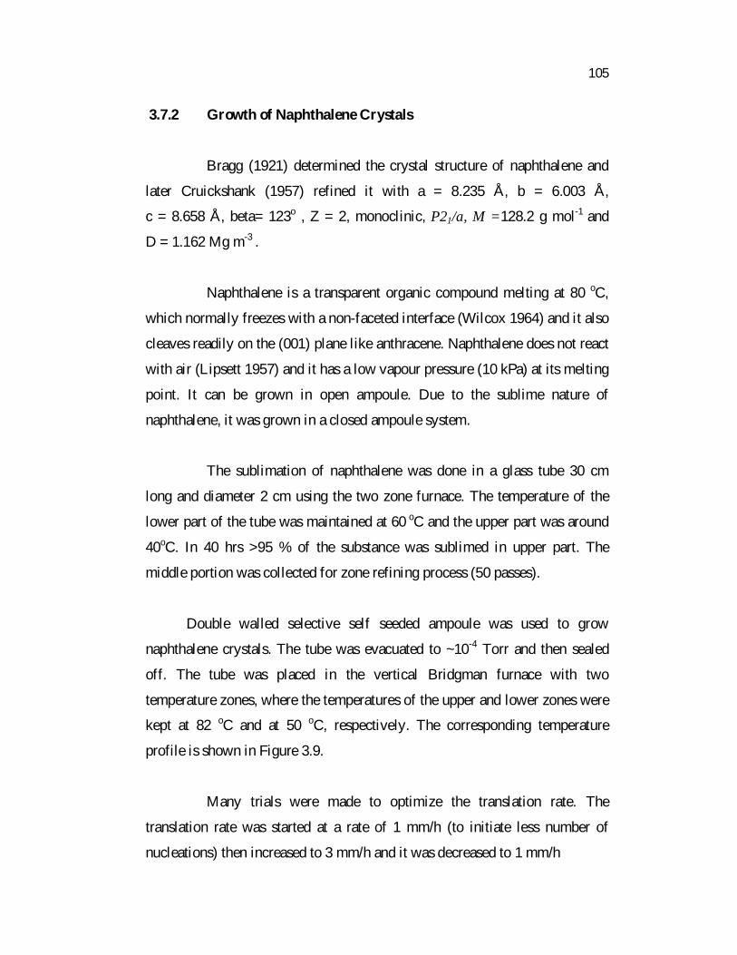
The growth runs were performed with 0.01, 0.03, 0.05 and
0.07 M % naphthalene in order to study the effect of variation in PPO
concentration on the scintillation properties of naphthalene. The optimum
crystal growth rates in the cylindrical region for 2 cm diameter ampoule were:
1 mm/h for 0.1 M % PPO doped naphthalene, 0.7 mm/h for 0.03 M % and
0.5 mm/h for 0.05 and 0.07 M % doped naphthalene.
3.8 CHARACTERIZATION
3.8.1 X-Ray Diffraction Analysis
The phase analysis and lattice parameters measurement of grown
crystals were performed by X-ray diffraction (XRD), Si was used as standard
sample. Powder X-ray diffraction (XRD) data of our grown crystal samples
were collected using Rich Seifert diffractometer with CuK radiation of
wavelength 1.5418 Å at room temperature. Intensities for the diffraction
peaks were recorded with a scan speed of 1°/min.
Page 21
110
Figure 3.12 PPO doped naphthalene crystals with ampoules
Page 22
111
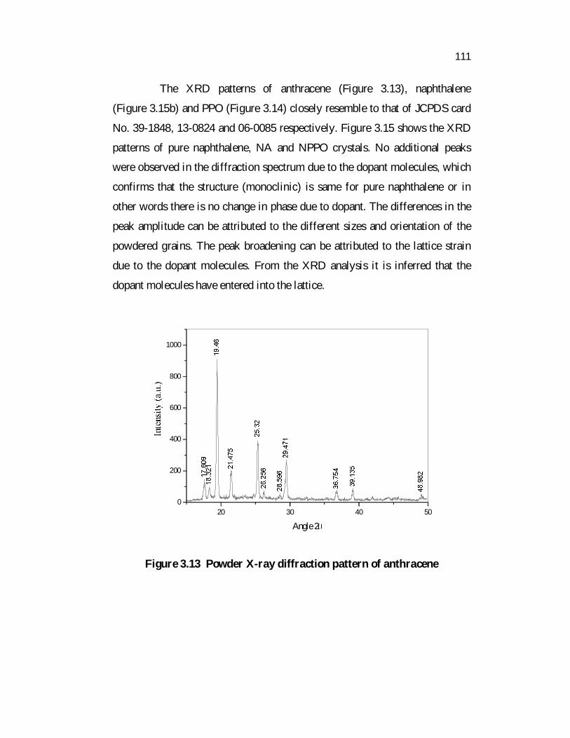
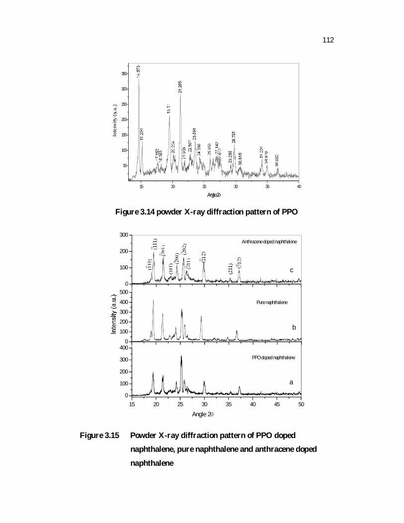
The XRD patterns of anthracene (Figure 3.13), naphthalene
(Figure 3.15b) and PPO (Figure 3.14) closely resemble to that of JCPDS card
No. 39-1848, 13-0824 and 06-0085 respectively. Figure 3.15 shows the XRD
patterns of pure naphthalene, NA and NPPO crystals. No additional peaks
were observed in the diffraction spectrum due to the dopant molecules, which
confirms that the structure (monoclinic) is same for pure naphthalene or in
other words there is no change in phase due to dopant. The differences in the
peak amplitude can be attributed to the different sizes and orientation of the
powdered grains. The peak broadening can be attributed to the lattice strain
due to the dopant molecules. From the XRD analysis it is inferred that the
dopant molecules have entered into the lattice.
20 30 40 500
200
400
600
800
1000
Angle 2
Figure 3.13 Powder X-ray diffraction pattern of anthracene
Page 23
112
15 20 25 30 35 40
50
100
150
200
250
300
350
Angle 2
Figure 3.14 powder X-ray diffraction pattern of PPO
15 20 25 30 35 40 45 500
100
200
300
4000
100
200
300
400
5000
100
200
300
Angle 2
PPO doped naphthalene
a
Pure naphthalene
b
Anthracene doped naphthalene
c
Figure 3.15 Powder X-ray diffraction pattern of PPO doped
naphthalene, pure naphthalene and anthracene doped
naphthalene
Page 24
113
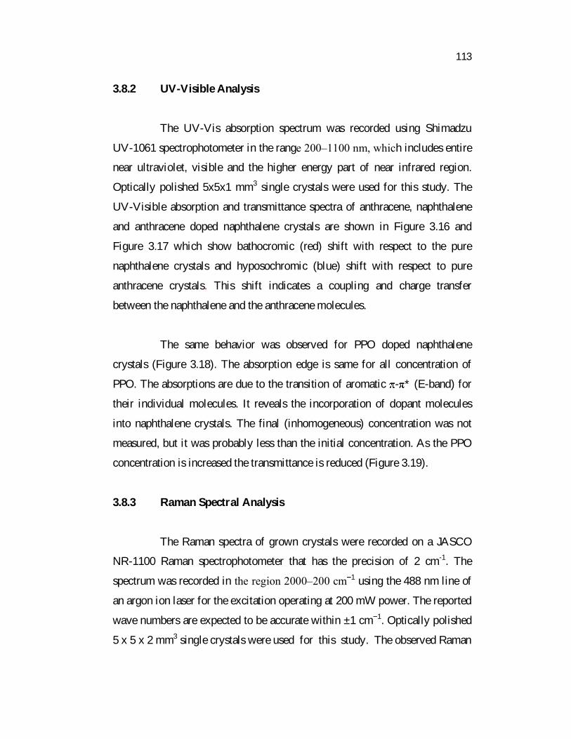
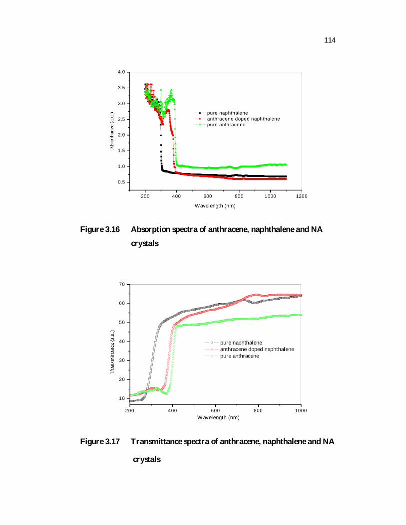
3.8.2 UV-Visible Analysis
The UV-Vis absorption spectrum was recorded using Shimadzu
UV-1061 spectrophotometer in the range 200�1100 nm, which includes entire
near ultraviolet, visible and the higher energy part of near infrared region.
Optically polished 5x5x1 mm3 single crystals were used for this study. The
UV-Visible absorption and transmittance spectra of anthracene, naphthalene
and anthracene doped naphthalene crystals are shown in Figure 3.16 and
Figure 3.17 which show bathocromic (red) shift with respect to the pure
naphthalene crystals and hyposochromic (blue) shift with respect to pure
anthracene crystals. This shift indicates a coupling and charge transfer
between the naphthalene and the anthracene molecules.
The same behavior was observed for PPO doped naphthalene
crystals (Figure 3.18). The absorption edge is same for all concentration of
PPO. The absorptions are due to the transition of aromatic - * (E-band) for
their individual molecules. It reveals the incorporation of dopant molecules
into naphthalene crystals. The final (inhomogeneous) concentration was not
measured, but it was probably less than the initial concentration. As the PPO
concentration is increased the transmittance is reduced (Figure 3.19).
3.8.3 Raman Spectral Analysis
The Raman spectra of grown crystals were recorded on a JASCO
NR-1100 Raman spectrophotometer that has the precision of 2 cm-1. The
spectrum was recorded in the region 2000�200 cm 1 using the 488 nm line of
an argon ion laser for the excitation operating at 200 mW power. The reported
wave numbers are expected to be accurate within ±1 cm 1. Optically polished
5 x 5 x 2 mm3 single crystals were used for this study. The observed Raman
Page 25
114
200 400 600 800 1000 1200
0.5
1.0
1.5
2.0
2.5
3.0
3.5
4.0
Wavelength (nm)
pure naphthalene anthracene doped naphthalene pure anthracene
Figure 3.16 Absorption spectra of anthracene, naphthalene and NA
crystals
200 400 600 800 1000
10
20
30
40
50
60
70
Wavelength (nm)
pure naphthalene anthracene doped naphthalene pure anthracene
Figure 3.17 Transmittance spectra of anthracene, naphthalene and NA
crystals
Page 26
115
200 400 600 800 1000 12000.0
0.5
1.0
1.5
2.0
2.5
3.0
3.5
4.0
Wavelength (nm)
Pure naphthalene 0.01 M % 0.03 M % 0.05 M % 0.07 M %
Figure 3.18 Absorption spectra of naphthalene and NPPO crystals
200 400 600 800 1000
10
20
30
40
50
60
70
80
Pure naphthalene 0.01 M % 0.03 M % 0.05 M % 0.07 M %
Wavelength (nm)
Figure 3.19 Transmittance spectra of naphthalene and NPPO crystals
Page 27
116
spectrum of naphthalene and anthracene is shown in Figures 3.20 and 3.21
respectively. The observed Raman peaks were assigned to the corresponding
wavenumber and it is compared with previous reported spectrum. It is in
better agreement with the wavenumber and Raman intensity data (calculated
as well as experimental) by Hideaki Shinohara et al (1998)
Figure 3.22 shows the observed Raman spectra of NA crystal and
Figure 3.23 shows the Raman spectrum of 0.03%PPO doped naphthalene
crystal. The unobserved changes in the spectral features from the pure to
doped crystals mean that the corresponding phonons are not sensitive to the
low impurity content. The same behaviour was found in other molecular
crystals, namely in biphenyl and naphthalene (Bellows and Prasad 1979) and
p-terphenyl (Amorim da Costa 1997, Amorim da Costa and Amado 1999).
These unobserved changes have been interpreted that the mixture lattice is
analagous to the crystal lattice of the dominating component. This may be due
to the very low concentration of impurities which does not essentially
influence either the line parameter of the vibrational spectrum in the external
frequency region, or probably the crystal packing. This is the evidence for the
absence of inter molecular bonding between the dopant and naphthalene
molecules. However 0.07 M % of PPO doped crystals has some spectral
distortions in the lower wavenumber side (Figure 3.24). But the peaks are
same as pure naphthalene crystals. There were no new scattering peaks,
indicating that dopants have entered the lattice of the crystal, replacing other
molecules, rather than entering the space of lattice. However, compared with
the naphthalene crystal, the intensity of the peaks of doped crystals varied.
Page 28
117
Wavenumber cm-1
Wavenumber cm-1
Figure 3.20 Raman spectrum of naphthalene crystal
Figure 3.21 Raman spectrum of anthracene crystal
Pure naphthalene crystal
Page 29
118
Anthracene doped naphthalene crystal
PPO doped naphthalene crystal
Wavenumber cm-1
Wavenumber cm-1
Figure 3.22 Raman spectrum of NA crystal
Figure 3.23 Raman spectrum of 0.03M% PPO doped naphthalene crystal
Page 30
119
0.07 M% PPO doped naphthalene crystal
Wavenumber cm-1
Figure 3.24 Raman spectrum of 0.07 M% PPO doped naphthalene
crystal
3.9 CONCLUSIONS
Pure and doped naphthalene crystals were grown using the self
seeded Bridgman growth. A two zone furnace was constructed and the
temperature profiles were studied using an integrated-circuit temperature
sensor IC LM35 with automated data logger. A home-made translation setup
was constructed for growth of low thermal conductivity materials in conical
type ampoules. The continuous decrease of the ampoule translation rate was
helpful in sustaining the flat interface throughout the growth and it helps in
the yield of highly transparent crystals. Good seeding was done using the
double walled crucible with additional necking facility. Growth rate of crystal
is not same as pure materials and optimized growth rate was found out. The
Page 31
120
grown crystals were characterized using powder X-ray diffraction studies and
the calculated cell parameters were in accordance with the JCPDS data. The
diffraction spectrum of doped crystals is same as for pure naphthalene or in
other words there is no change in phase due to dopant. The UV-Visible
transmission studies confirm that the dopant molecules are present in
naphthalene crystal. The doped crystal shows the red shift in the absorbance
spectra. The results on Raman spectral features of doped naphthalene in
relation to the corresponding features observed for pure crystalline
naphthalene show that the crystal doping in such small amounts does not lead
to noticeable changes of the intermolecular interaction energy. The
characterization analysis reveals that the dopant molecules are entered into the
lattice.


![A Comparative Study of Bond Order and Bond …of particular benzenoid hydrocarbons (naphthalene, anthracene, chrysene, quaterrylene and 1,2,8,9-dibenzacridine) [12]. Coulson described](https://static.documents.pub/doc/80x56/5f0baa8b7e708231d4319f95/a-comparative-study-of-bond-order-and-bond-of-particular-benzenoid-hydrocarbons.jpg)


![AR M G r o u p LLC€¦ · ARM Project 160443M-18 3 February 24, 2020 . AR M G r o u p LLC (benz[a]anthracene, benzo[a]pyrene, and naphthalene), two inorganics (total manganese and](https://static.documents.pub/doc/80x56/5ecbdef03a82cb4ab430f061/ar-m-g-r-o-u-p-llc-arm-project-160443m-18-3-february-24-2020-ar-m-g-r-o-u-p-llc.jpg)


