12
Copyright © 2003 David G Tarboton, Utah State University Chapter 3 Physical Factors Affecting Runoff
| Date post: | 06-Mar-2018 |
| Category: |
Documents |
| Upload: | nguyentruc |
| View: | 220 times |
| Download: | 0 times |

Copyright © 2003 David G Tarboton, Utah State University
Chapter 3 Physical Factors Affecting Runoff
Rainfall-Runoff Processes Chapter 3: 1
CHAPTER 3: PHYSICAL FACTORS AFFECTING RUNOFF
The general climatic regime controls the total volume of runoff in any region through its effect on the water balance. In a broad sense, over a time scale long enough that storage changes average out (are negligible), and over a region large enough or with boundary defined so that inflows (surface and subsurface) are negligible, the water balance may be stated as
P = Q + E (1)
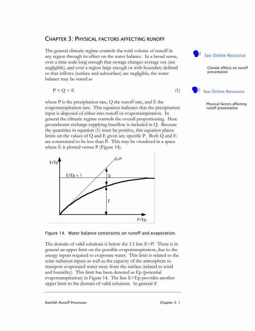
where P is the precipitation rate, Q the runoff rate, and E the evapotranspiration rate. This equation indicates that the precipitation input is disposed of either into runoff or evapotranspiration. In general the climatic regime controls the overall proportioning. Here groundwater recharge supplying baseflow is included in Q. Because the quantities in equation (1) must be positive, this equation places limits on the values of Q and E given any specific P. Both Q and E are constrained to be less than P. This may be visualized in a space where E is plotted versus P (Figure 14).
Figure 14. Water balance constraints on runoff and evaporation. The domain of valid solutions is below the 1:1 line E=P. There is in general an upper limit on the possible evapotranspiration, due to the energy inputs required to evaporate water. This limit is related to the solar radiation inputs as well as the capacity of the atmosphere to transport evaporated water away from the surface (related to wind and humidity). This limit has been denoted as Ep (potential evapotranspiration) in Figure 14. The line E=Ep provides another upper limit to the domain of valid solutions. In general if
See Online Resource
Physical factors affecting runoff presentation
See Online Resource
Climate effects on runoff presentation
Rainfall-Runoff Processes Chapter 3: 2
precipitation is large (P >> Ep) water is not going to be limited at the earth surface so E will approach Ep asymptotically for P tending to infinity. Also, if precipitation is small (P << Ep) water is very limited at the earth surface and may all evaporate, so E will approach the line E=P asymptotically as P tends to 0 approaching the origin. These constraints suggest a solution for the E versus P function of the form indicated in Figure 14. In Figure 14 the axes have been scaled by Ep to make them dimensionless. A nonlinear increase in Q with P as P/Ep increases is suggested, and the index P/Ep serves as an index of regional humidity or aridity, with P/Ep large (>1) in humid regions and small (<1) in arid regions.
0 More Intense % Rain Days Less Intense 100
100
MoreHumid
ETACT
ETPOT
%
MoreArid
0
75%
50%
25%Total Runoff
0%
MainlyHortonianOverland Flow
MainlySaturation
Overland Flow
Seasonal or storm period fluctuations
EpE
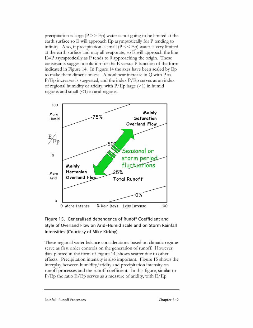
Figure 15. Generalised dependence of Runoff Coefficient and Style of Overland Flow on Arid-Humid scale and on Storm Rainfall Intensities (Courtesy of Mike Kirkby) These regional water balance considerations based on climatic regime serve as first order controls on the generation of runoff. However data plotted in the form of Figure 14, shows scatter due to other effects. Precipitation intensity is also important. Figure 15 shows the interplay between humidity/aridity and precipitation intensity on runoff processes and the runoff coefficient. In this figure, similar to P/Ep the ratio E/Ep serves as a measure of aridity, with E/Ep

Rainfall-Runoff Processes Chapter 3: 3
approaching 1 for humid regions. The runoff coefficient is defined as the ratio Q/P and expresses the percentage of total precipitation that becomes runoff.
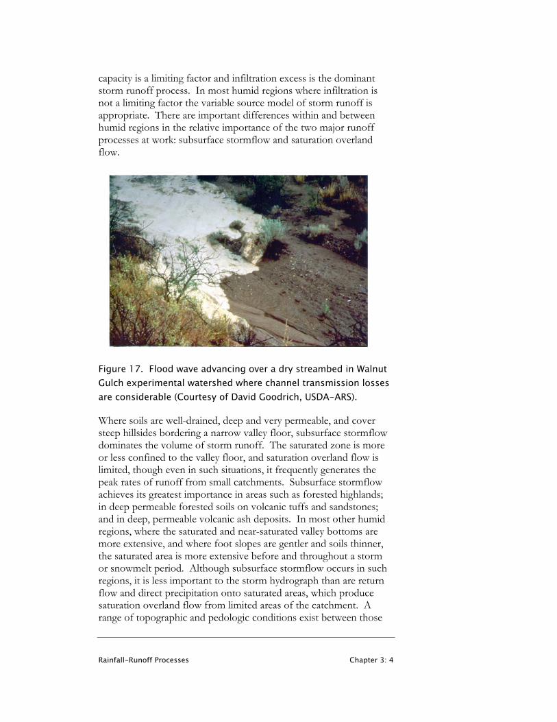
There is also a scale affect associated with the regional water balance that is different for humid and arid regions. Figure 16, collated by David Goodrich (personal communication 2003) shows data for four different areas in the U.S. In semi-arid regions like Arizona the mean annual runoff decreases with drainage area due to channel transmission losses. Most runoff is infiltration excess and the opportunity for infiltration increases as water progresses down the channel network. Figure 17 shows an advancing flood wave over a dry channel bed in the Walnut Gulch experimental watershed where channel transmission losses are considerable. Walnut Gulch, the San Pedro and Reynolds Creek in Idaho are all semi-arid watersheds where transmission losses increase with drainage area. In contrast to this in humid regions, such as the Coshocton watershed in Ohio, mean annual runoff increases with drainage area due to groundwater flow. Basically water that infiltrates and recharges groundwater in small watersheds adds to the baseflow of larger watersheds.
100
10
1
0.10.001 0.1 10 1000
Area (sq. miles)
Walnut Gulch, AZ
Reisel, TX
Coshocton, OH
Mea
n A
nnua
l R
unof
f (in
ches
) Reynolds Ck, ID
San Pedro, AZ
ID
AZ
TXOK
OHVA
GAFL
MS
MO
PAIA
Figure 16. Scale dependence of mean annual runoff for different geographic locations in the U.S. (Courtesy of David Goodrich, USDA-ARS). Following regional climatic regime and precipitation intensity, vegetation, land use, topography and soils, also exert controls on runoff processes. The following discussion based on Dunne and Leopold (1978) reviews these controls. Figure 18 summarizes the major controls on the various runoff processes. These vary with climate, vegetation, land use, soil properties, topography and rainfall characteristics. In arid and semi-arid regions and those disturbed by humans (through agriculture, urbanization and mining) infiltration
Rainfall-Runoff Processes Chapter 3: 4
capacity is a limiting factor and infiltration excess is the dominant storm runoff process. In most humid regions where infiltration is not a limiting factor the variable source model of storm runoff is appropriate. There are important differences within and between humid regions in the relative importance of the two major runoff processes at work: subsurface stormflow and saturation overland flow.
Figure 17. Flood wave advancing over a dry streambed in Walnut Gulch experimental watershed where channel transmission losses are considerable (Courtesy of David Goodrich, USDA-ARS). Where soils are well-drained, deep and very permeable, and cover steep hillsides bordering a narrow valley floor, subsurface stormflow dominates the volume of storm runoff. The saturated zone is more or less confined to the valley floor, and saturation overland flow is limited, though even in such situations, it frequently generates the peak rates of runoff from small catchments. Subsurface stormflow achieves its greatest importance in areas such as forested highlands; in deep permeable forested soils on volcanic tuffs and sandstones; and in deep, permeable volcanic ash deposits. In most other humid regions, where the saturated and near-saturated valley bottoms are more extensive, and where foot slopes are gentler and soils thinner, the saturated area is more extensive before and throughout a storm or snowmelt period. Although subsurface stormflow occurs in such regions, it is less important to the storm hydrograph than are return flow and direct precipitation onto saturated areas, which produce saturation overland flow from limited areas of the catchment. A range of topographic and pedologic conditions exist between those
Rainfall-Runoff Processes Chapter 3: 5
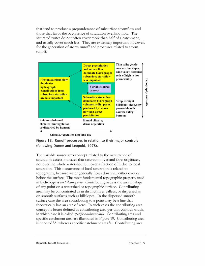
that tend to produce a preponderance of subsurface stormflow and those that favor the occurrence of saturation overland flow. The saturated zones do not often cover more than half of a catchment, and usually cover much less. They are extremely important, however, for the generation of storm runoff and processes related to storm runoff.
Horton overland flow dominates hydrograph; contributions from subsurface stormflow are less important
Direct precipitation and return flow dominate hydrograph; subsurface stormflow less important
Subsurface stormflow dominates hydrograph volumetrically; peaks produced by return flow and direct precipitation
Arid to sub-humid climate; thin vegetation or disturbed by humans
Humid climate; dense vegetation
Steep, straight hillslopes; deep,very permeable soils; narrow valley bottoms
Thin soils; gentle concave footslopes; wide valley bottoms; soils of high to low permeability
Climate, vegetation and land use
Topography and soils
Variable source concept
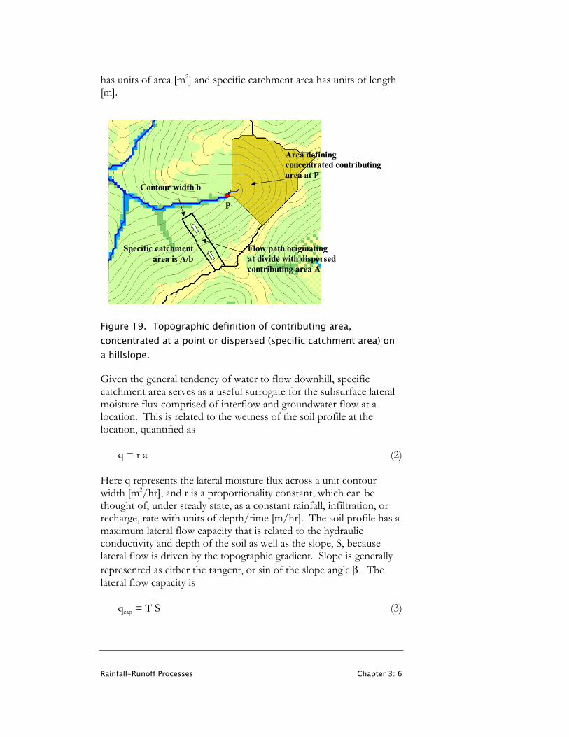
Figure 18. Runoff processes in relation to their major controls (following Dunne and Leopold, 1978). The variable source area concept related to the occurrence of saturation excess indicates that saturation overland flow originates, not over the whole watershed, but over a fraction of it due to local saturation. This occurrence of local saturation is related to topography, because water generally flows downhill, either over or below the surface. The most fundamental topographic property used in hydrology is contributing area. Contributing area is the area upslope of any point on a watershed or topographic surface. Contributing area may be concentrated as in distinct river valleys, or dispersed as on smooth surfaces such as hillslopes. In the dispersed smooth surface case the area contributing to a point may be a line that theoretically has an area of zero. In such cases the contributing area concept is better defined as contributing area per unit contour width, in which case it is called specific catchment area. Contributing area and specific catchment area are illustrated in Figure 19. Contributing area is denoted 'A' whereas specific catchment area 'a'. Contributing area
Rainfall-Runoff Processes Chapter 3: 6
has units of area [m2] and specific catchment area has units of length [m].
Flow path originating at divide with dispersed contributing area A
Contour width b
Specific catchmentarea is A/b
P
Area defining concentrated contributing area at P
Figure 19. Topographic definition of contributing area, concentrated at a point or dispersed (specific catchment area) on a hillslope. Given the general tendency of water to flow downhill, specific catchment area serves as a useful surrogate for the subsurface lateral moisture flux comprised of interflow and groundwater flow at a location. This is related to the wetness of the soil profile at the location, quantified as
q = r a (2)
Here q represents the lateral moisture flux across a unit contour width [m2/hr], and r is a proportionality constant, which can be thought of, under steady state, as a constant rainfall, infiltration, or recharge, rate with units of depth/time [m/hr]. The soil profile has a maximum lateral flow capacity that is related to the hydraulic conductivity and depth of the soil as well as the slope, S, because lateral flow is driven by the topographic gradient. Slope is generally represented as either the tangent, or sin of the slope angle β. The lateral flow capacity is
qcap = T S (3)
Rainfall-Runoff Processes Chapter 3: 7
Here qcap represents the lateral flow capacity of the soil profile per unit width [m2/hr] and T is called the transmissivity [m2/hr] and is the integral over depth of the hydraulic conductivity. (Hydraulic conductivity is defined and discussed in section 4 below.) The slope S is dimensionless. The relative wetness of a soil profile is related to the ratio of the lateral moisture flux to the lateral flow capacity from equations (2, 3), namely
STarw = (4)
This is based on the idea that for a soil profile to transport water laterally at capacity, it needs to approach saturation; however when the lateral flow is less than capacity the profile can be less wet. The topographic component of the wetness expression (4) is just a/S, which is commonly used as a topographic wetness index. More commonly this is written ln(a/S) or ln(a/tan β) because this is the way it was first expressed (Beven and Kirkby, 1979) in the definition of TOPMODEL (which will be discussed below) where there was an assumption of exponential decrease of hydraulic conductivity with depth that led to the logarithm in the definition. On steep slopes the distance over which flow occurs is the length along the slope, i.e. the hypotenuse of the triangle, so S is better defined as sin β. For most practical angles the difference between tan and sin is indistinguishable given the uncertainty in other quantities involved in these equations. The topographic wetness index is readily calculated using geographic information systems (GIS) from digital elevation models (DEMs) which are also now readily available. The topographic wetness index provides a way to identify and model locations likely to generate runoff by saturation excess and to quantify the variable source area concept. When the lateral water flux (equation 2) exceeds the lateral flow capacity (equation 3) the soil profile becomes completely saturated, so the variable source areas contributing to saturation excess overland flow can be identified as those locations where
a/S > T/r (5)
The supply of water to soil drainage (r in equation 2), or specific catchment area proportionality constant, quantifies the general antecedent wetness of the watershed. Under an assumption of steady state, r is also the per unit area baseflow. Higher r values result in a smaller threshold in equation (5) and larger variable source area. The

Rainfall-Runoff Processes Chapter 3: 8
wetness index and saturated area for two different T/r thresholds evaluated from a DEM is illustrated in Figure 20.
Figure 20. (a) ln (a/S) wetness index for a small watershed evaluated from a 30 m Digital Elevation Model. The gaps within the wetness index are where the slope is 0 and wetness index is formally undefined. (b) Saturated area based on this wetness index for two different T/r thresholds.

Rainfall-Runoff Processes Chapter 3: 9
Exercises
1. Saturation excess overland flow is most likely to occur in: A. Gently sloping areas where the water table is shallow B. Steep forested hillsides C. Urban areas D. Arid regions with compacted crusted soil surfaces
2. Infiltration excess overland flow is most likely to occur in:
A. Gently sloping areas where the water table is shallow B. Steep forested hillsides C. Arid regions with compacted crusted soil surfaces D. Urban areas
3. Infiltration excess overland flow is more likely to occur in:
A. A short gentle rainstorm B. A short intense rainstorm C. A long gentle rainstorm D. A snow blizzard
4. Saturation excess overland flow is more likely to occur in:
A. A short intense rainstorm with moderate total rainfall amount B. A short gentle rainstorm with small total rainfall amount C. A snow blizzard with all precipitation in the form of snow D. A long gentle rainstorm with large total rainfall amount
5. Saturated areas that contribute to saturation excess overland flow
are most likely larger A. At the end of a long dry spell B. At the end of the wet season
6. Interception is most likely to
A. Result in a large capillary fringe B. Increase the infiltration capacity C. Reduce the infiltration capacity D. Increase erosion E. Occur in an urban area F. Lead to increased infiltration excess overland flow G. Reduce the amount of runoff generated in a forested area
See Online Resource
Do the Chapter 3 Quiz

Rainfall-Runoff Processes Chapter 3: 10
7. The area contributing to saturation excess overland flow is likely to be larger: A. At the end of a rainstorm B. At the beginning of a rainstorm C. Midway through a rainstorm when the rainfall intensity is
highest D. Midway through a dry interstorm period
8. Following are annual precipitation and potential evaporation
estimates for five watersheds. P Ep Q E mm mm mm mm A 200 700 B 500 900 C 800 700 D 1200 900 E 2000 800
Fill in the missing Q and E values from the selections below: Q: 20, 100, 300, 400, 1350; E: 800, 650, 500, 400, 180
9. In a typical storm in a humid catchment the saturated area is: A. less than 50% of the area B. between 50% and 75% of the area C. greater than 75% of the area
Rainfall-Runoff Processes Chapter 3: 11
References
Beven, K. J. and M. J. Kirkby, (1979), "A Physically Based Variable Contributing Area Model of Basin Hydrology," Hydrological Sciences Bulletin, 24(1): 43-69.
Dunne, T. and L. B. Leopold, (1978), Water in Environmental Planning, W H Freeman and Co, San Francisco, 818 p.


