26 CHAPTER 3 QUADRUPLEX WINDING REDUNDANCY BRUSHLESS DC MOTOR 3.1 INTRODUCTION This chapter presents the design of new quadruplex winding redundancy permanent magnet brushless dc motor. The design is carried out based on the requirement specification and interface drawing of the motor for electromechanical actuator application in aerospace mechanism. The new quadruplex winding technique for reliability requirement is introduced. List of major components for the stator assembly and rotor assembly is provided. The motor volume is apportioned from the given overall dimensional constraint. Assuming the value of airgap flux density, the number of conductors for back-EMF and torque requirement is calculated. 3.2 DESIGN CONSIDERATION Before designing the motor for required specification, the fundamental design issues are considered. The size of the motor to produce the desired torque for radial flux motors stated as 2 T KD L (3.1) Where, T is torque in Nm K is a motor constant D is the airgap diameter, m L is the stack length, m
Transcript
26
CHAPTER 3
QUADRUPLEX WINDING REDUNDANCY BRUSHLESS
DC MOTOR
3.1 INTRODUCTION
This chapter presents the design of new quadruplex winding
redundancy permanent magnet brushless dc motor. The design is carried out
based on the requirement specification and interface drawing of the motor for
electromechanical actuator application in aerospace mechanism. The new
quadruplex winding technique for reliability requirement is introduced. List of
major components for the stator assembly and rotor assembly is provided. The
motor volume is apportioned from the given overall dimensional constraint.
Assuming the value of airgap flux density, the number of conductors for
back-EMF and torque requirement is calculated.
3.2 DESIGN CONSIDERATION
Before designing the motor for required specification, the
fundamental design issues are considered. The size of the motor to produce
the desired torque for radial flux motors stated as
2T KD L (3.1)
Where, T is torque in Nm
K is a motor constant
D is the airgap diameter, m
L is the stack length, m
27
Torque is linearly proportional to length
Torque is proportional to diameter squared
The ability to produce force increases linearly with diameter ( D)
and force produces torque which is proportional to radius (D/2).
3.2.1 Motor Diameter
Mechanical power output is directly proportional to torque whereas
the torque is proportional to square of the diameter as given in 3.1. A motor
having larger diameter generates more mechanical power which states the
motor diameter should be maximized. There are constraints that limit the
diameter of the motor. The important constraint in this application is space
limitation and interface with the mechanism. The mass and inertia of the
motor also plays a major role in operation of the motor in space mechanism
requiring maximum torque to inertia ratio. The torque to inertia ratio of a
motor decreases as the square of the diameter. The diameter of the motor
should be selected based on the above constraints.
Alternate equation for the development of torque in a motor is
given by
( / 2)gT PB IL D (3.2)
where P = No. of poles, Bg = Airgap flux density.
In order to increase the power output for a fixed diameter motor the
electrical loading and magnetic loading shall be increased.
3.2.2 Active Motor Length
The torque developed by the motor is directly proportional to the
active length of the motor. But by increasing the length, the mass and volume
28
of the motor get increased. Also the resistance of the winding depends on the
core length and hence the resistive loss increases as longer copper wire is
required for more active length. Therefore, increasing the motor active length
does not improve the efficiency of the motor.
3.2.3 Ampere-Turn
Ampere turn is the product of number of turns and the winding
current. The winding inductance increases square of the number of turns.
High inductance affects the motor electrical time constant. The winding
resistance is proportional to resistive loss. Increase in number of turns
increases the resistive loss. But increase in number of turns reduces the
winding current for the required torque and hence copper loss is reduced as it
is proportional to square of the current. If the conductor size is constant, the
cross sectional area increases as turns increases. The increase in slot area
increases the mass of the stator core which affect the power density and
increase in slot current increases the armature reaction field. This increases
the core loss in the magnets and decreases the airgap flux density due to stator
core saturation.
3.2.4 Airgap Flux Density
In permanent magnet brushless dc motor the magnetic loading is
maximized to get the required torque output and this requires high energy
permanent magnet material. The airgap flux density will increase by
increasing the permeance coefficient of the magnetic circuit. High permeance
coefficient implies larger magnet length and shorter effective airgap length.
Decreasing the effective airgap length increases the cogging torque. And
hence for a high magnetic loading the volume of the magnet material and its
29
energy product should be high and ferromagnetic material is required to
concentrate the flux. The saturation in the stator core teeth also limits the
improvement in the airgap flux density.
3.2.5 Number of Poles
The selection of pole numbers depends on the airgap diameter.
Increasing the number of poles in a fixed area decreases the magnet width to
accommodate the additional magnets. With this the magnet leakage flux
increases which reduces the flux density in the airgap. Increasing the number
of poles increases the rotational frequency of the motor. The core loss
depends on the rotational frequency of the motor. The hystersis loss is directly
proportional to frequency and eddy current loss is directly proportional to
square of the frequency. The increase in rotational frequency increases the
core loss in the motor which decreases the efficiency. The advantage of more
poles is that the overhang length will be reduced and which reduces the end
winding resistance and inductance. The back iron thickness gets reduced by
increasing the number of poles. In a high performance brushless dc motor the
design goal is to improve the tradeoff between the electrical loading and
magnetic loading by finding a method to increase one in manner that does not
diminish the other.
3.3 MAGNETIC CIRCUIT DETAILS
Brushless permanent magnet motor operation relies on the
conversion of energy from electrical to magnetic to mechanical and magnetic
energy which depends on spatial distribution of flux in the motor plays a
central role in the production of torque. A simple geometry of the magnetic
field can be found analytically to determine the magnetic field distribution in
30
the motor. The direction of magnetic field is assumed for the preliminary
design of the motor (Duane C. Hanselman 1994).
The stator and rotor structure of brushless dc motor is shown in
Figure 3.1 and 3.2. The magnetic circuit model of one flux loop shown in
Figure 3.3 composed of one half of the two magnets and associated stator and
rotor back iron. The magnetic field due to winding current is not considered.
By considering rR and sR to be negligible with respect to gR and mlR , the
magnetic circuit can be simplified as shown in Figure 3.4.
Figure 3.1 Bldc motor stator-rotor structure
Figure 3.2 Permanent magnet and magnetic material structure
31
Figure 3.3 Magnetic circuit model of the structure
rR = Rotor back iron reluctance
sR = Stator back iron reluctance
2 gR = Reluctance of the one half of airgap with compensation for
slotting
r /2 = Flux source of one half of the magnet
2 mR = Reluctance of one half of the magnet
g /2 = Airgap flux flowing through one half of the airgap cross
section area
mlR = Reluctance modeling the flux leakage from magnet to
magnet
Figure 3.4 Simplified magnetic circuit
32
The airgap permeance describes the net permeance seen by the
magnet flux that enters the stator. This flux emanates from cross sectional
area is given by
1+ m =g p 2A L (3.3)
the airgap permeance. Pg is
o 1+p m =g 2 eP
g (3.4)
eg = Effective airgap length,
m = +e cr
lg g k (3.5)
p = Magnet pole pitch
m =Magnet fraction
ck = Carter coefficient
ml = Magnet radial thickness
g = Physical airgap length
The airgap flux with the above equations
1=g r1+ /r c mlk k PC (3.6)
PC = Permeance coefficient
mlk = Magnet leakage factor
33
The flux concentration factor, m =g
AC
A (3.7)
The airgap flux density, =g r1+ / PCr c ml
CB B
k k (3.8)
rB = Remenance flux
3.4 DESIGN APPROACH
The design approach starts with basic motor geometrical
constraints. The volume for stator assembly and rotor assembly is apportioned
from the given overall dimensional specification of the motor. The motor
stack length and airgap diameter are fixed based on the designer experience.
Once the motor volume is fixed, the magnetic loading for the torque
production is calculated. The magnetic circuit details determining the number
of poles and slots are worked out. The permeance coefficient and magnet
operating point is found for the magnetic circuit. The size, shape and energy
product of the magnet are determined to maximize the magnetic loading.
Once the magnetic loading is calculated to carry maximum flux in the given
magnetic circuit, the electrical loading is worked out. The current required to
generate the required motor output torque is then determined. Given the
desired back-EMF at rated speed, the number of conductors for generating the
back-EMF is calculated. The phase inductance and winding resistance are
computed from the winding information.
The proposed work describes the design and development of
brushless dc motor having four independent winding in its armature assembly
as per the specification requirement of motor for electromechanical actuator
application. The design of armature stator assembly, permanent magnet rotor
assembly and Hall sensor assembly are worked out. Armature design is a
quadruplex three phase star connected winding separately housed in four
34
quadrants of the armature stator providing physical and electrical isolation of
each quadrant winding for reliability and redundancy. The permanent magnet
rotor assembly is designed conforming to the quadruplex armature in which
each quadrant of the armature and the magnet rotor performs independently as
a separate brushless dc motor. The Hall sensor assembly is a triplex
redundancy separate assembly housed in the stator core to sense the rotor
position for six step commutation logic.
3.5 SPECIFICATION REQUIREMENT OF THE MOTOR
Table 3.1 Requirement specification of the motor
1 Type PM BLDC torque motor-frameless2 Winding Quadruplex redundancy three phase
winding3 Position sensor Latch type Hall effect device
(Triplex redundancy)4 Commutation scheme Six step trapezoidal commutation5 Stall torque (a) 8 Nm per quadrant at 12.4 A (Nominal)
(b) 32 Nm total at 49.6 A6 No-load speed 1000 rpm @ supply voltage of 75V DC7 Insulation resistance >100M at 250V DC8 Torque constant 0.66 ± 7% Nm/A9 Back-EMF constant 0.66± 7% V/(rad/s)
10 Winding resistance 2.4 ± 10% , (line-line)11 Winding inductance 10.2 ± 30 mH, (line-line)12 Rotor inertia 8.8 e-4 ± 10% Kgm²13 Cogging torque < 2 % of Peak torque14 Ripple Torque < 15 % of Peak torque15 Load cycle As per the sketch16 Dimension As per the interface drawing17 Operational
temperature80 C
18 Drive electronics Four independent power drives for the foursets of windings.PWM type. Switching frequency 10 kHz.
35
3.5.1 Interface Drawing
Figure 3.5 Interface drawing of the motor
36
3.6 SPECIFICATION DERIVED
Table 3.2 Design goal
Motor Frameless bldc motor
Supply Voltage 75 V, DC
Three phase winding in each quadrant Star connection
Current per quadrant 12.4 A
Current for four quadrants 12.4 * 4 = 49.6 A
Load cycle As per sketch
Hall sensors for six sequence commutation Triplex redundancy
Overall dimensions As per interface drawing
Stator outer diameter, (max) 129 mm
Rotor inner diameter, (min) 50.8 mm
Rotor inertia 8.8e-4 Kg m²
Overall stator length (max) 69mm
Overall rotor length (max) 49mm
Armature stack length 43mm
Winding overhang inner diameter 77.47mm
Operational temperature 80 C
Maximum torque per quadrant 8 Nm (Nominal)
Total torque: (8Nm * 4 quadrant) 32 Nm (Nominal)
No-load speed@ 75 V, DC 1000 rpm
Line to line Winding resistance 2.4 ohms ± 10 %
Line to line Winding inductance 10.2mH ± 30 %
Three sets of Hall sensor signal output for redundancy. Independent four quadrant winding design for winding isolation andredundancy.
37
3.7 LIST OF MAJOR ELEMENTS
(1) Permanent magnet rotor assembly
Rotor back iron ring
Permanent magnets
Potting compound
(2) Armature stator assembly
Electrical lamination sheet
Slot insulation
Copper wire
Lead wires
Solder wire, lead
Flux
Heat shrinkable sleeves
Epoxy bonding resin
Potting compound
Hall effect sensors and PCB
(3) Tools and fixtures
Lamination stacking fixture
Coil winding fixture
Stack holding fixture during winding
Overhang forming fixture
Armature potting fixture
Rotor magnet assembly fixture
Stator-rotor assembly fixture
Testing fixture
38
3.8 MAGNETIC CIRCUIT PHYSICAL DIMENSIONS
Based on the design input and output requirements and the given
overall dimensions two-third of the annular volume is apportioned for stator
assembly and one-third to the magnet rotor assembly since high coercive
magnets is used for the rotor design. This apportionment meets the winding
overhang inner diameter needed and the inner diameter of the stator stack is
taken as 77mm for magnetic circuit calculations.
The following input dimensions are worked out from the given
volume constraints. The magnetic circuit details are calculated with the
following dimensions.
Stator outer diameter 129mm
Stator inner diameter 77mm
Stack length 43mm
Physical airgap length 0.5mm
Rotor outer diameter 76.0mm
Rotor inner diameter 50.8mm
The torque motor diameter and length is specified and fixed. The
torque output of the motor which is the product of electrical loading and
magnetic loading is found by calculating the work done per revolution (Wr ).
Wr = (Total magnetic loading) * (Total electrical loading)
Electrical loading = IZ
Magnetic loading = P
Where I = Winding current in Ampere
Z =No. of conductors
P = No. of poles
39
Wr =(P ) (IZ) (3.9)
2 22 T= gD LB q (3.10)
where gB = Airgap flux density in Tesla
q = Ampere conductors
T = Torque in Nm
Torque developed by the motor is given by
2gT = D LB q
2 (3.11)
The magnetic loading is provided by high energy rare earth
permanent magnets in the rotor assembly. The radial thickness of the magnet
is apportioned from the rotor return ring. The undesired cogging torque in the
motor is also depends on magnet width. The magnet width is selected such
that it reduces the cogging torque. The volume of the magnet is worked out
and the magnet permeance coefficient is calculated. The magnet operating
point is found from the high energy magnet demagnetization curve. Assuming
the airgap flux density over the pole arc and with the values of D and L , the
needed Ampere conductors to develop the required torque is found out using
the above relation. Once the total magnetic loading and total electrical loading
are worked out, the number of poles and slots are selected. The aim of the
proposed work is to select slot-pole combination based on the following
constraints.
1. Number of slots for quadruplex winding redundancy
2. Number of poles conforming to the stator quadruplex
redundancy
3. To keep the cogging torque minimum.
4. To reduce the core losses
40
3.9 QUADRUPLEX WINDING REDUNDANCY TECHNIQUE
This thesis focus on the design of brushless dc motor with
quadruplex redundant three phase star connected winding in the armature
stator for reliability requirement of electromechanical actuator. The present
application requirement needs four independent motors operation in single
magnetic core for functional redundancy of the actuator system. A new
winding method is adopted in stator assembly to isolate four quadrant
windings electrically and physically from each other for quadruplex winding
redundancy.
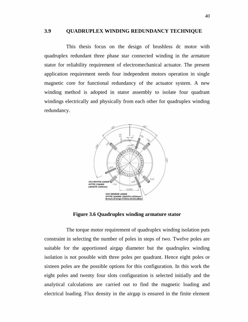
Figure 3.6 Quadruplex winding armature stator
The torque motor requirement of quadruplex winding isolation puts
constraint in selecting the number of poles in steps of two. Twelve poles are
suitable for the apportioned airgap diameter but the quadruplex winding
isolation is not possible with three poles per quadrant. Hence eight poles or
sixteen poles are the possible options for this configuration. In this work the
eight poles and twenty four slots configuration is selected initially and the
analytical calculations are carried out to find the magnetic loading and
electrical loading. Flux density in the airgap is ensured in the finite element
41
analysis. The magnetic circuit details are validated with the analysis result.
Based on the design simulation the fabrication of the motor is carried out. For
the eight poles twenty four slots configuration, each quadrant has six slots for
three phase winding and the slots per pole per phase is one for eight poles
rotor. Three coils are used to wound for three phase winding of a quadrant.
The 23 SWG copper wire is selected for the assumed current density around
10 A/mm² for the given duty cycle. The slot space factor is around 0.4 for the
calculated number of turns in the slot for the required torque. While winding
the armature coils only two-third of the designed turns were able to put into
the slots due to overhang length limitation constraint for mechanical interface
with the mechanism. Also the line to line resistance value meets the
requirement specification with this two-third calculated turns. To overcome
the overhang problem two motor configurations, 48 slots stator and 60 slots
stator with common 16 poles rotor, are designed. To reduce the number of
conductors the magnetic loading is increased by increasing the magnet
volume and changing energy product of the magnets from 25 MGOe to 28
MGOe. The magnetic circuit is iterated to the increased magnetic loading.
The analytical design is validated with finite element analysis software and
magnetic circuit details are plotted for comparison. Based on the simulation
results the above two proto type motors (Integral slot and Fractional slot) are
developed. Both the motor are experimentally tested and the results are
tabulated for comparison of all the four quadrants performance output.
3.10 COGGING TORQUE
The major disadvantage of brushless dc motor is production of
undesired cogging torque and ripple torque. Cogging torque is due to
interaction between the rotor permanent magnets and the tooth of the stator. It
is generated by the interaction of airgap flux and stator reluctance variation in
the airgap. The rotor tends to align to the stator teeth even without winding
42
excitation. This cogging torque superimposed on the desired output torque
causes vibration and acoustic noise in the motor while running. Techniques to
reduce cogging torque play a prominent role in motor design.
Cogging torque is given by
212
gcog g
dRT
d (3.13)
Where g is the airgap flux and gR is the airgap reluctance.
In this design stator slots are skewed to reduce cogging torque by
making gdRd
near zero value over angular rotation of the torque. Skewing can
be done either for magnet or to the slots. Skewing the magnet increases the
magnet cost. Skewing the slots increases the ohmic loss because the increased
slot length requires long wire. Both integral slot pitch and fractional slot pitch
configurations are considered for the stator assembly design. The stator slots
are skewed for one slot pitch for integral slot configuration and half slot pitch
for fractional slot configuration. The cogging torque reduction technique in
rotor assembly is also adopted. The pole pitch is selected such that the pole
slot combination reduces the cogging torque. The demerit of skewing the
stator slots is, it reduces the developed torque by skew factor as the effective
Ampere-turn under the pole pitch is reduced. Limiting the magnet width to
reduce the cogging torque lowers the magnetic loading.
The magnitude of the cogging torque for the torque motor
configuration with and without skewing is evaluated using finite element
analysis tool. However it is possible to meet the cogging torque specification
by introducing one slot pitch skew for the integral slot and half slot pitch for
fractional slots.
43
3.11 LOAD CYCLE
Figure 3.7 Load cycle of the motor
The load cycle per quadrant of the motor for ball screw actuator
mechanism is given in Figure 3.7. The peak load current is 12.4 Ampere and
no-load current is 1.5 Ampere per quadrant.
Load cycle : 1225 seconds
Peak load duration : 25 seconds
No-load duration : 1200 seconds
For the given periodic and intermittent duty cycle, the equivalent
RMS current producing the same loss is calculated for the selection of copper
conductor diameter for the armature winding.
I = 3.3 A (Continuous RMS current)
The gage of the copper wire is selected based on the current density
and resistance per phase requirement. Normally class C insulation with
current density in the range of 10 A/mm² to 15 A/mm² is suggested for space
grade application. For the current density around 11 A/mm² for continuous
Time in sec
44
operation, 23 SWG copper wire with bare conductor diameter of 0.61mm and
cross sectional area of 0.292 mm² is selected. Total mean length of the copper
wire is calculated to find the line to line winding resistance. The number of
conductors per coil is calculated from back-EMF constant and speed of
rotation. The slot space factor is ensured for winding the coils in the slot
comfortably and within the overhang limitation for interfacing the armature
with the mechanism.
3.12 PERMANENT MAGNET MAGNETIC CIRCUIT
The different types of permanent magnet material available are
Alnico, Ferrite, Samarium Cobalt (SmCo) and Neodymium Iron Boron
(NdFeB). At room temperature NdFeB has the highest energy product of all
commercially available magnets. The high remanence and coercivity permit
marked reductions in motor size for the same output compared with motors
using Ferrite (ceramic) magnets. For the magnetic circuit consisting of
permanent magnet, high permeable ferromagnetic material and airgap, the
operating point of the magnet is calculated with the following equations.
By Guass’s law the flux density in the magnet and airgap are
related by
m m g gB A B A (3.14)
0m m
m g m
B A gH A l
(3.15)
g g gm m
m m
B H A gB H
A l (3.16)
2 gm m
m
WB H
V (3.17)
45
where mB = Magnet flux density
mA = Magnet area
gB = Airgap flux density
gA = Airgap area
g = Airgap length
ml = Magnet thickness
mH = Field density of the magnet
gW = Magnetic energy stored in the airgap
mV = Volume of the magnet
3.13 BACK-EMF AND NUMBER OF CONDUCTORS
From the given requirement specification, the following values are
taken.
Torque constant, tK = 0.645 Nm/A
Back-EMF constant, bK = 0.645 V/(rad/sec)
No-load speed = 1000 rpm
Supply voltage = 75 V
The back-EMF, E is found from the back-EMF constant,
E = bK x (rad/sec) = 67.5 V
Number of conductors required to generate the back-EMF is worked out from
the basic relation, E BLv
Surface velocity, v = sDn m/s
No. of conductors for generating the torque for six step commutation is found
from the following relation.
46
s
EBL Dn
Z = (3.18)
where sn is revolution per second
The calculated number of turns is distributed in the stator volume depending
upon the pole-slot combination.
3.14 SUMMARY
The requirement specification of the electrical motor for the
electromechanical actuator in the space mechanism is given. The performance
and geometrical input data are derived from the specification for the design of
the advanced motor. The mechanical and electrical interface drawing for the
motor in the actuator mechanism is provided. The approach for the design of
the motor is explained briefly. The insight of new quadruplex winding
redundancy technique is investigated. The continuous RMS current for
selection of copper wire is worked out for the given operation load cycle. The
main dimensions are worked out from the given volume constraint. The major
considerations for the design of the motor are also listed. The effect of
cogging torque on the performance of the motor and the method to limit the