SECTION 2: SIGNING AND PAVEMENT MARKING PLAN REQUIREMENTS ........... 3
SECTION 3: VDOT PROJECT DEVELOPMENT PROCESS ......................................... 5
SECTION 4: SIGNING AND PAVEMENT MARKING DESIGN PROCESS ................... 6
STEP 1 – OBTAIN DESIGN INPUT DATA ..................................................................... 6
STEP 2- FIELD REVIEW AND SIGNING AND PAVEMENT MARKING INVENTORY ......................................................................................................... 6
STEP 3- EVALUATE UTILITIES AND ROADWAY GEOMETRY .................................. 8
STEP 4- PREPARE PRELIMINARY SIGNING AND MARKING PLANS AND MEET WITH VDOT APPROVING ENTITY .................................................. 8
STEP 5 - PREPARE SIGNING AND PAVEMENT MARKING PLAN SHEETS ............................................................................................................. 15
STEP 6- PREPARE SIGN PANEL SPECIAL DETAIL SHEETS .................................. 19
STEP 13- PREPARE SUMMARY OF QUANTITIES SHEET ....................................... 31
VDOT Traffic Engineering Design Standards and Guidelines Chapter 3 – Signing and Pavement Markings
1
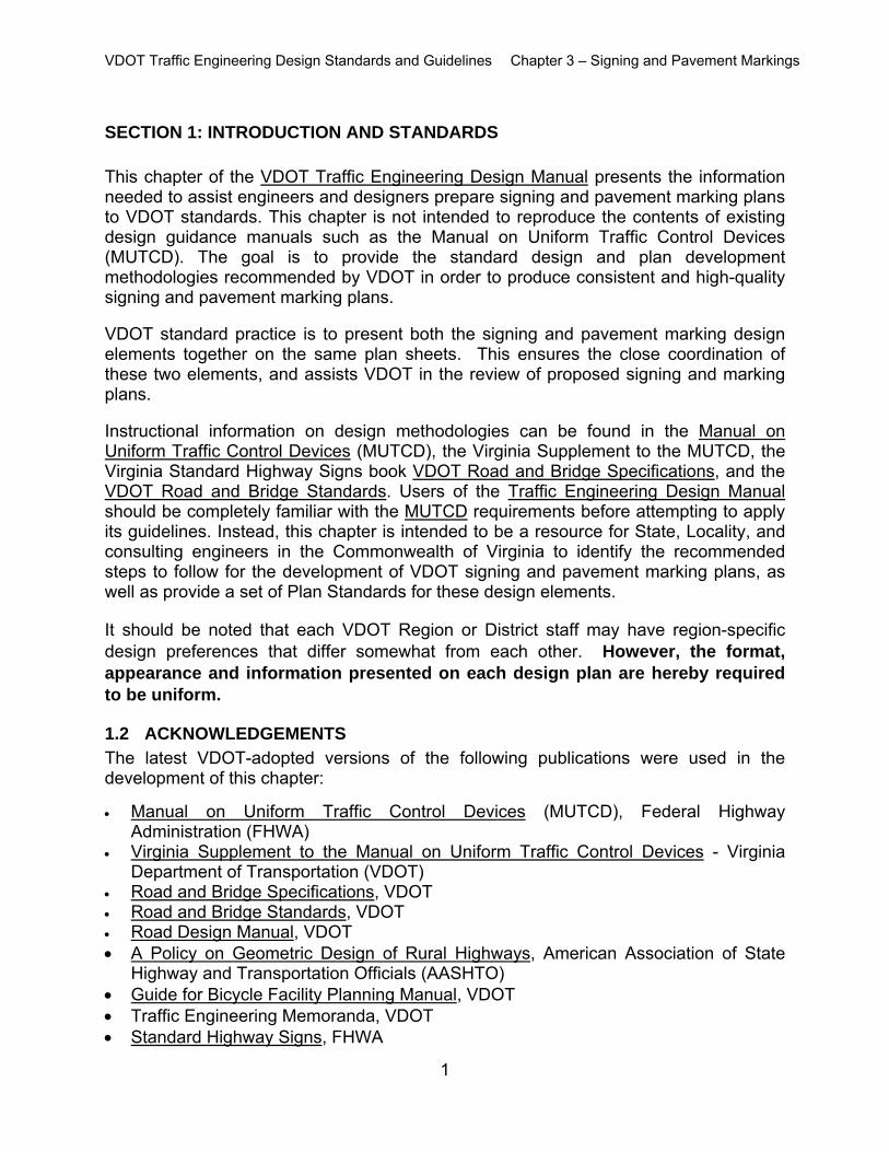
SECTION 1: INTRODUCTION AND STANDARDS This chapter of the VDOT Traffic Engineering Design Manual presents the information needed to assist engineers and designers prepare signing and pavement marking plans to VDOT standards. This chapter is not intended to reproduce the contents of existing design guidance manuals such as the Manual on Uniform Traffic Control Devices (MUTCD). The goal is to provide the standard design and plan development methodologies recommended by VDOT in order to produce consistent and high-quality signing and pavement marking plans. VDOT standard practice is to present both the signing and pavement marking design elements together on the same plan sheets. This ensures the close coordination of these two elements, and assists VDOT in the review of proposed signing and marking plans. Instructional information on design methodologies can be found in the Manual on Uniform Traffic Control Devices (MUTCD), the Virginia Supplement to the MUTCD, the Virginia Standard Highway Signs book VDOT Road and Bridge Specifications, and the VDOT Road and Bridge Standards. Users of the Traffic Engineering Design Manual should be completely familiar with the MUTCD requirements before attempting to apply its guidelines. Instead, this chapter is intended to be a resource for State, Locality, and consulting engineers in the Commonwealth of Virginia to identify the recommended steps to follow for the development of VDOT signing and pavement marking plans, as well as provide a set of Plan Standards for these design elements.
It should be noted that each VDOT Region or District staff may have region-specific design preferences that differ somewhat from each other. However, the format, appearance and information presented on each design plan are hereby required to be uniform.
1.2 ACKNOWLEDGEMENTS
The latest VDOT-adopted versions of the following publications were used in the development of this chapter:
Manual on Uniform Traffic Control Devices (MUTCD), Federal Highway Administration (FHWA)
Virginia Supplement to the Manual on Uniform Traffic Control Devices - Virginia Department of Transportation (VDOT)
Road and Bridge Specifications, VDOT Road and Bridge Standards, VDOT Road Design Manual, VDOT A Policy on Geometric Design of Rural Highways, American Association of State
Highway and Transportation Officials (AASHTO) Guide for Bicycle Facility Planning Manual, VDOT Traffic Engineering Memoranda, VDOT Standard Highway Signs, FHWA
VDOT Traffic Engineering Design Standards and Guidelines Chapter 3 – Signing and Pavement Markings
2
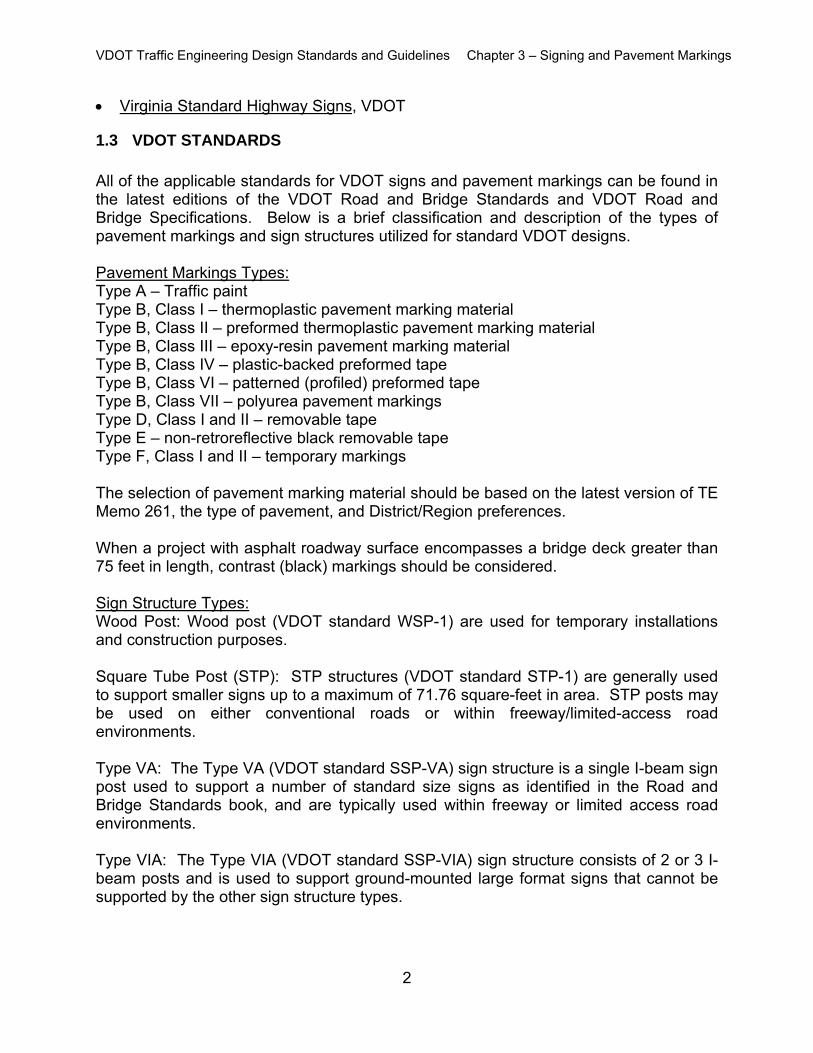
Virginia Standard Highway Signs, VDOT
1.3 VDOT STANDARDS All of the applicable standards for VDOT signs and pavement markings can be found in the latest editions of the VDOT Road and Bridge Standards and VDOT Road and Bridge Specifications. Below is a brief classification and description of the types of pavement markings and sign structures utilized for standard VDOT designs. Pavement Markings Types: Type A – Traffic paint Type B, Class I – thermoplastic pavement marking material Type B, Class II – preformed thermoplastic pavement marking material Type B, Class III – epoxy-resin pavement marking material Type B, Class IV – plastic-backed preformed tape Type B, Class VI – patterned (profiled) preformed tape Type B, Class VII – polyurea pavement markings Type D, Class I and II – removable tape Type E – non-retroreflective black removable tape Type F, Class I and II – temporary markings The selection of pavement marking material should be based on the latest version of TE Memo 261, the type of pavement, and District/Region preferences. When a project with asphalt roadway surface encompasses a bridge deck greater than 75 feet in length, contrast (black) markings should be considered. Sign Structure Types: Wood Post: Wood post (VDOT standard WSP-1) are used for temporary installations and construction purposes. Square Tube Post (STP): STP structures (VDOT standard STP-1) are generally used to support smaller signs up to a maximum of 71.76 square-feet in area. STP posts may be used on either conventional roads or within freeway/limited-access road environments. Type VA: The Type VA (VDOT standard SSP-VA) sign structure is a single I-beam sign post used to support a number of standard size signs as identified in the Road and Bridge Standards book, and are typically used within freeway or limited access road environments. Type VIA: The Type VIA (VDOT standard SSP-VIA) sign structure consists of 2 or 3 I-beam posts and is used to support ground-mounted large format signs that cannot be supported by the other sign structure types.
VDOT Traffic Engineering Design Standards and Guidelines Chapter 3 – Signing and Pavement Markings
3
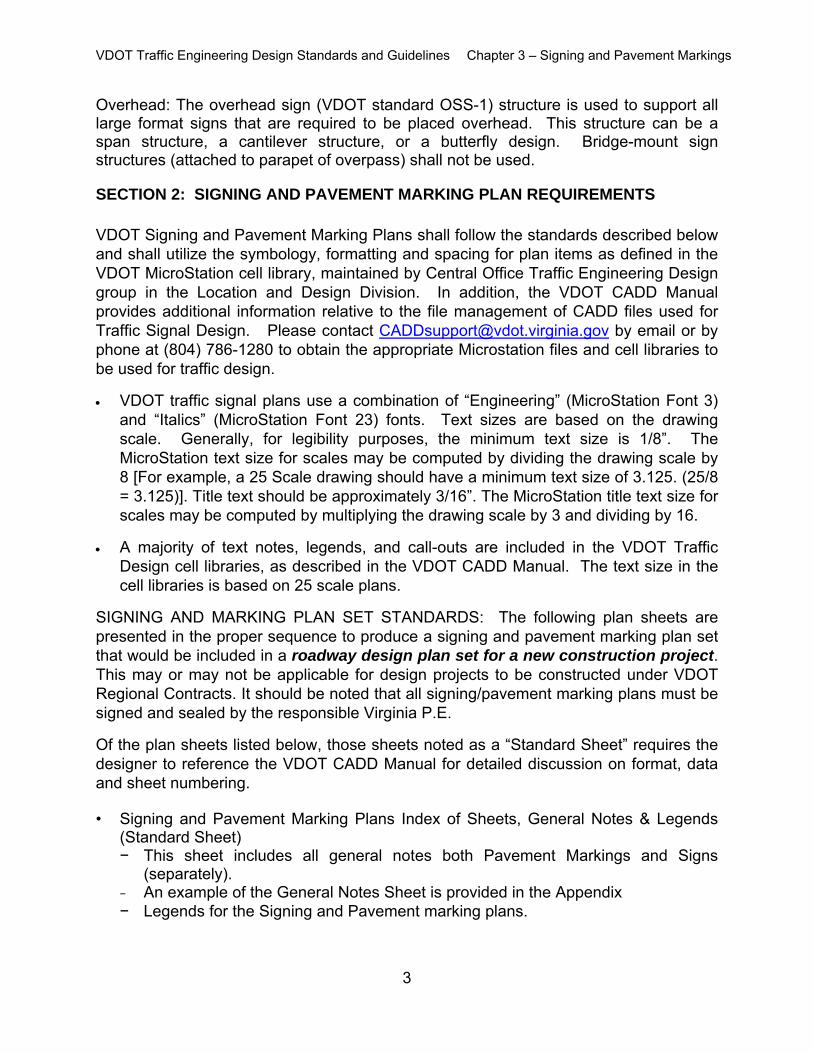
Overhead: The overhead sign (VDOT standard OSS-1) structure is used to support all large format signs that are required to be placed overhead. This structure can be a span structure, a cantilever structure, or a butterfly design. Bridge-mount sign structures (attached to parapet of overpass) shall not be used.
SECTION 2: SIGNING AND PAVEMENT MARKING PLAN REQUIREMENTS VDOT Signing and Pavement Marking Plans shall follow the standards described below and shall utilize the symbology, formatting and spacing for plan items as defined in the VDOT MicroStation cell library, maintained by Central Office Traffic Engineering Design group in the Location and Design Division. In addition, the VDOT CADD Manual provides additional information relative to the file management of CADD files used for Traffic Signal Design. Please contact [email protected] by email or by phone at (804) 786-1280 to obtain the appropriate Microstation files and cell libraries to be used for traffic design.
VDOT traffic signal plans use a combination of “Engineering” (MicroStation Font 3) and “Italics” (MicroStation Font 23) fonts. Text sizes are based on the drawing scale. Generally, for legibility purposes, the minimum text size is 1/8”. The MicroStation text size for scales may be computed by dividing the drawing scale by 8 [For example, a 25 Scale drawing should have a minimum text size of 3.125. (25/8 = 3.125)]. Title text should be approximately 3/16”. The MicroStation title text size for scales may be computed by multiplying the drawing scale by 3 and dividing by 16.
A majority of text notes, legends, and call-outs are included in the VDOT Traffic Design cell libraries, as described in the VDOT CADD Manual. The text size in the cell libraries is based on 25 scale plans.
SIGNING AND MARKING PLAN SET STANDARDS: The following plan sheets are presented in the proper sequence to produce a signing and pavement marking plan set that would be included in a roadway design plan set for a new construction project. This may or may not be applicable for design projects to be constructed under VDOT Regional Contracts. It should be noted that all signing/pavement marking plans must be signed and sealed by the responsible Virginia P.E.
Of the plan sheets listed below, those sheets noted as a “Standard Sheet” requires the designer to reference the VDOT CADD Manual for detailed discussion on format, data and sheet numbering.
• Signing and Pavement Marking Plans Index of Sheets, General Notes & Legends (Standard Sheet) − This sheet includes all general notes both Pavement Markings and Signs
(separately). − An example of the General Notes Sheet is provided in the Appendix
− Legends for the Signing and Pavement marking plans.
VDOT Traffic Engineering Design Standards and Guidelines Chapter 3 – Signing and Pavement Markings
4
• Insertable Sheets (Standard Sheets) − These shall be provided, as required for each project.
• Summary of Quantities Sheet (Standard Sheet) − Summary of Quantities include the pay items required for each plan sheet.
• Detail Sheets (Standard Sheets) – There are several standard detail sheets required for signing and pavement
marking plans. They are as follows: o Sign Figure Details o Sign Schedules
• Occasionally, additional detail may be necessary on the intersection plan sheets to thoroughly illustrate the design intent. These details may include: − Non-Standard Sign Structure Details − Non-Standard Type VA and VIA Sign Structure Details − Overhead (O/H) Sign Structure Elevation Detail Sheets Pavement Marking Details. An example of a Pavement Marking Detail Sheet is
provided in the Appendix. Additional details may be necessary to clearly illustrate the placement of the
pavement markings, pavement markers, object markers or delineation.
• Plan Sheets: Plan sheets shall include the following (at a minimum): − North arrow − Scale, typically 1”=50’ − Stationing − Street names and Route Numbers − Intersection or roadway geometry (to scale) − Curb ramps (as required) − Right of Way − Show underground and overhead utilities, if applicable − Show all graphics and illustrations depicting signing and pavement marking
elements including: o Existing and Proposed Sign Placements, including sign removals or
replacements o Indication of Existing and Proposed Sign orientations o Existing Sign Structure and/or Sign Panel Type o Existing Sign Action and Measurement & Payment Item o Proposed Sign Assembly Numbers/Sign Text Numbers o Proposed Pavement Markings, and eradications, if applicable o Radii for turn lane extensions through intersections o Spacing requirements for transverse markings o Lane width dimensions o Pavement Marking Legend o Pavement Markers, if applicable o Object Markers, if applicable o Delineators, if applicable
VDOT Traffic Engineering Design Standards and Guidelines Chapter 3 – Signing and Pavement Markings
5
SECTION 3: VDOT PROJECT DEVELOPMENT PROCESS
The following describes how the signing and pavement marking design process within a new construction project aligns with the VDOT Project Development Process. Information pertaining to the Project Development Process can be found on VDOT’s website or through the VDOT Project Management Office. The specific plan requirements for each project milestone can be found in checklist format in VDOT’s Form LD-436. Scoping Phase: Determine if the limits of the survey will accommodate the sign design, and if not,
schedule/or obtain the appropriate survey information, as described in Step 1 of the Signing and Pavement Marking Design Process.
Preliminary Design Phase: Complete a field review of existing signing and pavement marking inventory, and a
review of utilities and proposed roadway geometry to identify limits of signing and pavement markings, as described in Steps 2 and 3.
Ensure all signs (especially large format signs) can be accommodated within existing or proposed right of way. If not, determine any permanent easements or right of way needed to accommodate the signs.
Complete airport clearance review for overhead sign structures. Prepare the preliminary plan sheets required for the specific project and meet with
VDOT Regional/District representative as detailed in Step 4. Detailed Design Phase: Prepare the signing and pavement marking plan sheets as detailed in Step 5. Final Design Phase: Complete Steps 6 through 13. This includes preparing all required detail sheets,
and a sign schedule. Also develop general, quantities summaries and plan notes.
VDOT Traffic Engineering Design Standards and Guidelines Chapter 3 – Signing and Pavement Markings
6
SECTION 4: SIGNING AND PAVEMENT MARKING DESIGN PROCESS The VDOT Signing and Pavement Marking Design Process is a sequence of design steps that build on each other to produce a set of signing and marking plans. The following are recommended design steps for producing a VDOT Signing and Pavement Marking Plan.
STEP 1 – OBTAIN DESIGN INPUT DATA
• Obtain preliminary design information. This includes the following: − Determine if the limits of survey for the subject project will accommodate the
signing and pavement marking designs. If not, request additional survey. − Obtain any approved and relevant traffic studies or previous roadway plans that
may provide guidance regarding the pavement marking or sign designs.
The signing and pavement marking design parameters and requirements appropriate for the facility should be determined through coordination with the responsible VDOT Regional/District representative at the onset of the sign design. The following issues should be addressed:
− Identification of new ground mounted signs and/or overhead signs − Post types − Guide sign messages − Size and type of letter series − Lighting requirements − Luminaire retrieval system and/or catwalk − Supplemental signing − Logo signing − Reuse, Dispose, Salvage existing signs/structures − Pavement marking types to be utilized − Aesthetic considerations such as ornamental posts, color on the back of the sign
panel, galvanized coating of sign structures, crosswalk marking preferences, etc. − Pavement marker requirements, if any − Location of existing traffic control devices to ensure that proposed signs are not
blocking view of the other traffic control devices − Available sight distances to and between traffic control devices
STEP 2- FIELD REVIEW AND SIGNING AND PAVEMENT MARKING INVENTORY A signing/pavement marking inventory/field review should be performed to document all existing sign data, sign structures, and pavement markings.
• The sign inventory includes identifying sign messages, locations, color and size of the sign panels, qualitative evaluation of the condition of the panels, type of posts, overhead sign structures and span lengths, sign lighting systems, and sign structure walkways. All existing signs shall be identified on the sign inventory.
VDOT Traffic Engineering Design Standards and Guidelines Chapter 3 – Signing and Pavement Markings
7
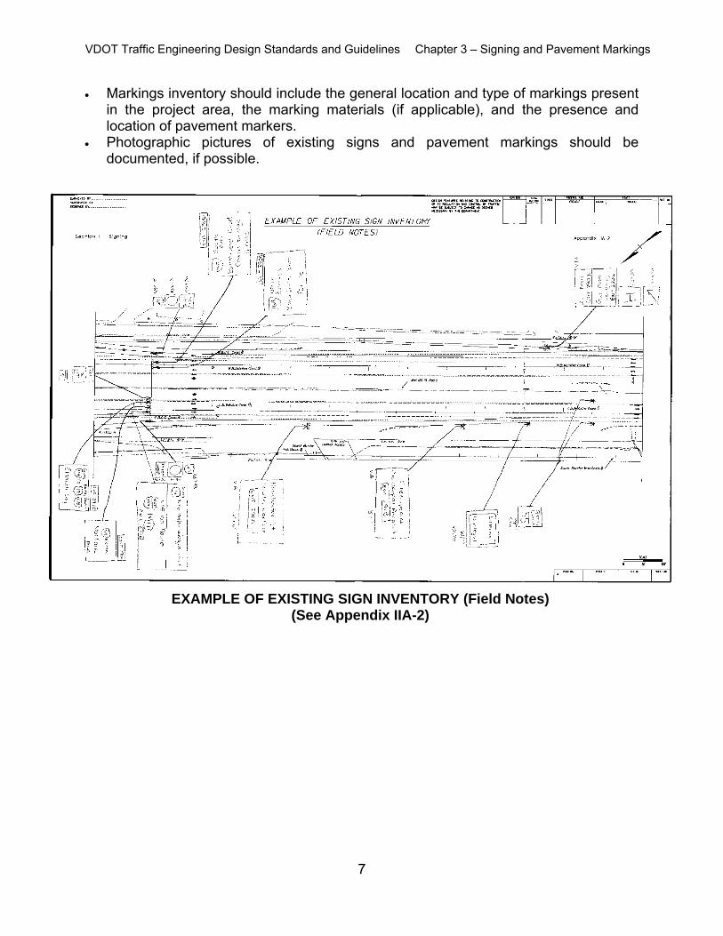
Markings inventory should include the general location and type of markings present in the project area, the marking materials (if applicable), and the presence and location of pavement markers.
Photographic pictures of existing signs and pavement markings should be documented, if possible.
EXAMPLE OF EXISTING SIGN INVENTORY (Field Notes) (See Appendix IIA-2)
VDOT Traffic Engineering Design Standards and Guidelines Chapter 3 – Signing and Pavement Markings
8
STEP 3- EVALUATE UTILITIES AND ROADWAY GEOMETRY
(Proposed Construction Plans) Utility location plans as well as proposed utility adjustments that may be planned for the near future or during the project development period need to be identified. Potential geometric deficiencies relative to providing adequate signing at proper
spacing need to be noted and reviewed with the project designers and district representatives.
It is also necessary to identify, as early as practical, proposed plans for retaining
walls, noise walls or any obstacle that could be in conflict with sign structure placement.
A key area that can be overlooked during the early stages of design is the
project limits. What may appear to be a good location for the project to terminate for the other design disciplines may not be adequate for traffic control devices. Inadequacies in the transition from the project’s cross-section to the existing roadway cross-section will be revealed when the preliminary pavement marking and sign designs are developed at the project limits for the final design configuration, as well as the maintenance of traffic plans. Ensuring proper transitions at the project limits also includes all intersection side streets for primary and secondary road projects. Proper evaluation at the project limits will eliminate the need for obtaining additional right of way at the late stages of design or accepting less than ideal design conditions.
STEP 4- PREPARE PRELIMINARY SIGNING AND MARKING PLANS AND MEET WITH VDOT APPROVING ENTITY
After completion of the existing sign inventory, the existing signs should be shown (dashed) on the proposed construction plans. Proposed signs and sign removals are also illustrated on proposed construction plans sheets, as shown in the example plan provided in the Appendix. Preliminary pavement marking sketches support the development of the traffic control device designs for signs and traffic signals. It can also reveal geometric discrepancies that may otherwise appear to be properly designed. The sketches only need to illustrate the lane line layout and may not be needed for the entire project. The level of effort in preparing the preliminary pavement marking sketches should be kept to a minimum.
VDOT Traffic Engineering Design Standards and Guidelines Chapter 3 – Signing and Pavement Markings
9
Preliminary pavement marking sketches and preliminary sign design should be developed concurrently when the road project involves complicated lane configuration design. The lane configurations can become difficult to evaluate without pavement marking sketches, when a combination of lane changes (lane drop or exit only lane, acceleration lane, deceleration lane, and lane reduction transition) is being designed within an interchange. Preparing the preliminary sign design requires a clear understanding of the lane configurations. In order to develop and design the proposed signing plan, the designer should set up a meeting with the appropriate VDOT District and/or other agencies that have an interest in the project to discuss, comment and mark up proposed construction plans that indicate the preliminary existing and proposed signs. This meeting should consider/decide the following: Guide sign messages/color Regulatory, Warning, Logo and Supplemental signing Size and type of letter series (upper and lower case) Sign lighting systems Placement of signs, longitudinal along roadway Utility, wall and drainage structure conflicts must be addressed Sign structure types Placement of signs in relation to the sidewalk, if any Discuss applicable VDOT sign design policies Spacing between signs and traffic control devices APPLICABLE SIGN DESIGN POLICIES: Any nonstandard signs not in the MUTCD or Virginia Supplement should be
submitted to VDOT Central Office Traffic Engineering Division for review and approval.
It should be noted that VDOT has established a moratorium on new bridge parapet
mount sign structures, and has identified span length limits for ancillary structures, as highlighted in TE-375 / IIM-S&B-89.
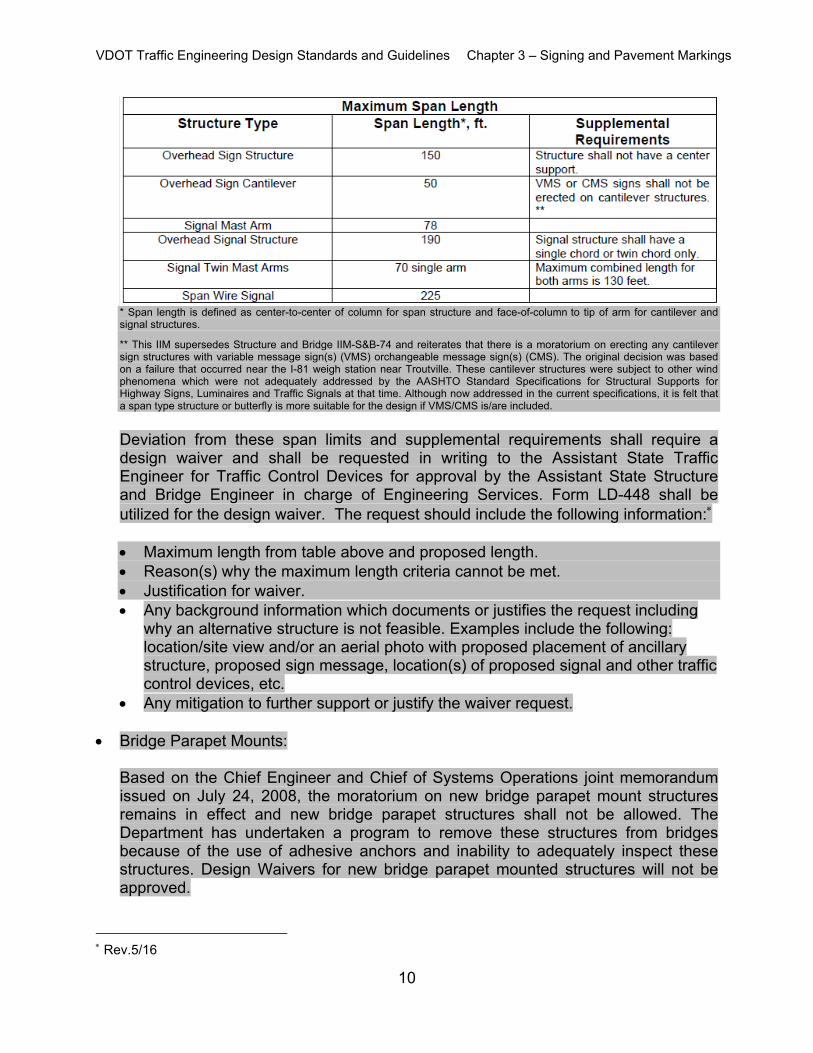
Span Length Limits for Ancillary Structures:
The following table provides span limits that shall apply to structures:
Rev.5/16
VDOT Traffic Engineering Design Standards and Guidelines Chapter 3 – Signing and Pavement Markings
10
* Span length is defined as center-to-center of column for span structure and face-of-column to tip of arm for cantilever and signal structures.
** This IIM supersedes Structure and Bridge IIM-S&B-74 and reiterates that there is a moratorium on erecting any cantilever sign structures with variable message sign(s) (VMS) orchangeable message sign(s) (CMS). The original decision was based on a failure that occurred near the I-81 weigh station near Troutville. These cantilever structures were subject to other wind phenomena which were not adequately addressed by the AASHTO Standard Specifications for Structural Supports for Highway Signs, Luminaires and Traffic Signals at that time. Although now addressed in the current specifications, it is felt that a span type structure or butterfly is more suitable for the design if VMS/CMS is/are included.
Deviation from these span limits and supplemental requirements shall require a design waiver and shall be requested in writing to the Assistant State Traffic Engineer for Traffic Control Devices for approval by the Assistant State Structure and Bridge Engineer in charge of Engineering Services. Form LD-448 shall be utilized for the design waiver. The request should include the following information:
Maximum length from table above and proposed length. Reason(s) why the maximum length criteria cannot be met. Justification for waiver. Any background information which documents or justifies the request including
why an alternative structure is not feasible. Examples include the following: location/site view and/or an aerial photo with proposed placement of ancillary structure, proposed sign message, location(s) of proposed signal and other traffic control devices, etc.
Any mitigation to further support or justify the waiver request.
Bridge Parapet Mounts: Based on the Chief Engineer and Chief of Systems Operations joint memorandum issued on July 24, 2008, the moratorium on new bridge parapet mount structures remains in effect and new bridge parapet structures shall not be allowed. The Department has undertaken a program to remove these structures from bridges because of the use of adhesive anchors and inability to adequately inspect these structures. Design Waivers for new bridge parapet mounted structures will not be approved.
Rev.5/16
VDOT Traffic Engineering Design Standards and Guidelines Chapter 3 – Signing and Pavement Markings
11
Overhead Sign Structure Determination:
The Manual on Uniform Traffic Control Devices (MUTCD) cites several locations where overhead signing is explicitly required or recommended (MUTCD Section 2A.17, Section 2E, Section 2F, Section 2G. Therefore, it is assumed that signs are generally post-mounted unless one of the specified conditions is met, or unless other constraints or traffic conditions indicate a need for overhead signing. The engineer should also verify there is no additional guidance in the Virginia Supplement to the MUTCD before using this checklist.
The engineer should field evaluate the existing conditions at all proposed sign locations and shall consider the following as part of an engineering study to determine if an overhead sign structure should be considered (MUTCD Section 2A.17:3):
• Traffic volume at or near capacity – A higher volume translates to a reduced level of service and an expectation of greater traffic congestion and less freedom for lane changing. Overhead signs permit longer sight lines and longer target visibility for sign legibility.
• Complex interchange design – Multi-lane exit ramps, left exit ramps, cloverleaf configurations, and interchanges with collector-distributor roadways benefit from, and sometimes require, overhead sign placement.
• Three or more lanes in each direction – Multi-lane roadways place some drivers more than 60 lateral feet from post-mounted guide signs with two or more lanes of traffic potentially obscuring important guidance information.
• Restricted sight distance – Post-mounted signs can be obscured by roadway alignment (horizontal curves), geometry (vertical alignment), and roadside objects (overcrossing structures, noise barriers, retaining walls).
• Closely-spaced interchanges – Where interchanges are closely spaced (often in urbanized areas), the available space for post-mounted signs with unobstructed sight lines can be very limiting. It is often necessary to place multiple signs with different messages at one location, which cannot be accomplished with post-mounted signs.
• Multi-lane exits – Research has found that drivers benefit from the additional guidance of lane use arrows on guide signs to indicate proper lane alignment for multi-lane exit ramps, particularly for locations with lane drops (Exit Only) and option lanes (Arrow-per-Lane or diagrammatic signs).
• Large percentage of trucks – As the percentage of trucks increases in the traffic stream, the probability of an adjacent truck obscuring the sight line to a post-mounted sign increases. For roads with high truck percentages (e.g. I-81 and I-77) it can often be difficult to see ground-mount signs. If this criteria is one of the
VDOT Traffic Engineering Design Standards and Guidelines Chapter 3 – Signing and Pavement Markings
12
determining factors, butterfly sign structures should be considered as a way to raise the signs to the point where their visibility is no longer obscured by trucks.
• Street lighting background – Street lighting can be both a benefit and a distraction to the viewing of post-mounted signs. The street light poles increase the visual clutter and can obscure the sight lines to post-mounted signs. Lack of street lighting can make signs placed outside the clear zone difficult to read as motor vehicle headlights have a limited angle of incidence.
• High-speed traffic (for non-freeway signing) – As indicated in MUTCD Section 2A.17, overhead signs should be used on expressways and freeways which are typically high speed facilities. Overhead signs provide more target value for drivers to read and understand the message, even at higher speeds. NOTE: this should only be considered a criterion when evaluating signing on conventional roads. Since all freeways and interstates are, by default, high-speed, this criterion should not be considered for signs on freeways/interstates.
• Consistency of sign message location through a series of interchanges – Driver expectancy is a key consideration in the design of highway features. If drivers are used to guidance information overhead along a particular roadway segment, utilizing post-mounted guide signs within that segment can be disconcerting and distracting.
• Insufficient space for post-mounted signs – In areas with limited rights-of-way or roadside features that restrict the available space for post-mounted signs, overhead signs should be considered.
• Junction of two freeways – Freeway-to-freeway interchanges are often complex driving environments with multiple on and off ramps that typically experience the highest traffic volumes, high traffic speeds, and a large percentage of trucks. This combination of factors favors use of overhead signs.
• Left exit ramps – Left exits violate the driver expectancy of exiting to the right. Therefore, the higher target value of overhead signs is critical to provide the drivers with guidance information well in advance of the exit to allow for proper lane alignment and safe lane changing behaviors.
Locations where overhead sign structures SHALL be used to mount highway signs Engineer SHALL use an overhead sign structure if any one of the following conditions applies:
If a Pull-Through Sign is used (MUTCD Section 2E.12)
If an Arrow-Per-Lane sign is used (MUTCD Section 2E.21)
If a Diagrammatic guide sign is used (MUTCD Section 2E.22)
VDOT Traffic Engineering Design Standards and Guidelines Chapter 3 – Signing and Pavement Markings
13
If an Exit Direction sign contains lanes that are not shown on the Advance Guide signs (MUTCD)
If the sign is a major guide sign for an interchange lane drop (MUTCD Section 2E.24:2)
If the sign is an Exit Direction sign for an interchange lane drop (MUTCD Section 2E.36:5)
If signing a freeway-to-freeway interchange, at the 1 Mile location and at the theoretical gore for each connecting ramp (MUTCD Section 2E.44:5)
If signing a cloverleaf interchange, for the last Advance Guide sign for the second exit, and the Exit Direction sign for the first exit; and at the Exit Direction sign for the second exit (MUTCD Section 2E.45:3; see also Section 2E.36:13)
If signing a cloverleaf interchange with collector-distributor roadways, for the guide signs at the exits from the collector-distributor roadway (MUTCD Section 2E.46:3)
For non-Open-Road ETC lanes, all guide signs at the toll plaza SHALL be overhead (mounted to the toll plaza canopy) to indicate the type of collection or vehicle associated with a particular toll plaza lane (MUTCD Section 2F.16)
If access to Preferential lanes is restricted to designated locations, Advanced Guide and Preferential Lane Entrance Direction Signs (MUTCD Section 2G.04:7, 2G.11:4 and 2G.12:1)
If installing R3-13, R3-14, R3-15, R3-44 or R3-45 series signs (defined as Overhead Preferential Lane regulatory signs) and changeable lane control signal signs (MUTCD Table 2G-1 & Sect. 2G.03:10, 2G.05:3, 2G.07 and Fig. 2G-1, 2G-3 & 2G-21 thru 2G-24)
Locations where overhead sign structures SHOULD be used to mount highway signs If a SHALL condition does not apply, the Designer should conduct an engineering study (use engineering judgment) based on the criteria listed on below and if any of the following “should” statements presented below apply:
If the sign is for a multi-exit interchange (Exit Direction for first, Advance Guide sign for second) (MUTCD Section 2E.36:13; see also Section 2E.45:3)
For an Exit Direction sign, if there is less than 300 feet from the upstream end of the deceleration lane to the theoretical gore (MUTCD Section 2E.36:4)
If regulatory signs or messages are used to restrict vehicle types or payment types to specific lanes at a toll plaza (MUTCD Section 2F.05:3 and 2F.14:1)
If some or all toll plaza lanes require a stop, the W9-6 and W9-6a signs (Toll Plaza Warning signs) or plaques at 1 Mile and ½ Mile locations (MUTCD Section 2F.06:2)
If the toll plaza diverges from a mainline-aligned Open-Road ETC lane, the advance sign at 1 Mile and ½ Mile in advance of the divergence (MUTCD Section 2F.15:2)
VDOT Traffic Engineering Design Standards and Guidelines Chapter 3 – Signing and Pavement Markings
14
If Preferential Lane regulatory signs are used on freeways and expressways with overhead general-purpose lane guide signs (MUTCD Sections 2G.03 and 2G.17)
If egress from Preferential lanes is restricted to designated locations, Advance Guide and Preferential Lane Egress Direction Signs (MUTCD Section 2G.13:5 and 2G.15:3)
VDOT Traffic Engineering Design Standards and Guidelines Chapter 3 – Signing and Pavement Markings
15
Upon completion of an engineering study, an overhead sign structure should be considered if: Any two of the Section 2A.17:3 conditions apply, or If one of the Section 2A.17:3 conditions and one of the ”should” cases from the list above apply.
Locations where overhead sign structures SHALL NOT be used to mount highway signs Unless one of the above SHALL conditions apply, use of an overhead sign structure shall not be considered if any one of the following conditions applies:
If overhead sign supports cannot be installed outside the clear zone or cannot be shielded within the clear zone (MUTCD Section 2A.19:1)
If overhead sign supports will result in a sidewalk or pedestrian access route width less than 4’0”, or will intrude into a shared use path (pursuant to MUTCD Section 2A.19:12 and the VDOT Road Design Manual)
For all Exit Gore signs (MUTCD Section 2E.37.2)
For all Specific Service signs (Refer to MUTCD Figure 2J-2 and Virginia’s Integrated Directional Signing Program/IDSP Policy)
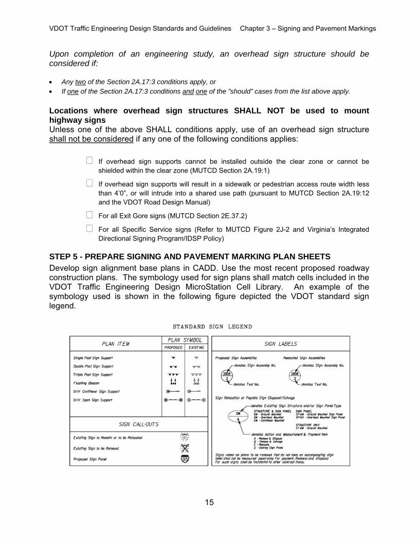
STEP 5 - PREPARE SIGNING AND PAVEMENT MARKING PLAN SHEETS Develop sign alignment base plans in CADD. Use the most recent proposed roadway construction plans. The symbology used for sign plans shall match cells included in the VDOT Traffic Engineering Design MicroStation Cell Library. An example of the symbology used is shown in the following figure depicted the VDOT standard sign legend.
VDOT Traffic Engineering Design Standards and Guidelines Chapter 3 – Signing and Pavement Markings
16
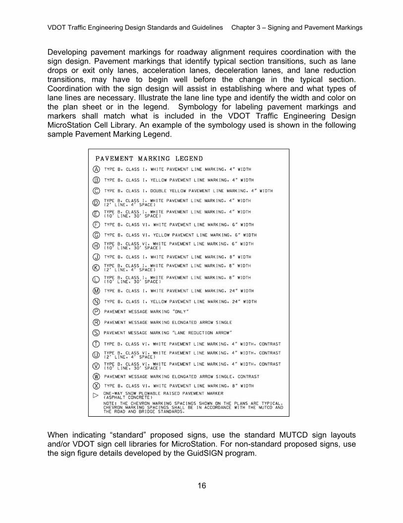
Developing pavement markings for roadway alignment requires coordination with the sign design. Pavement markings that identify typical section transitions, such as lane drops or exit only lanes, acceleration lanes, deceleration lanes, and lane reduction transitions, may have to begin well before the change in the typical section. Coordination with the sign design will assist in establishing where and what types of lane lines are necessary. Illustrate the lane line type and identify the width and color on the plan sheet or in the legend. Symbology for labeling pavement markings and markers shall match what is included in the VDOT Traffic Engineering Design MicroStation Cell Library. An example of the symbology used is shown in the following sample Pavement Marking Legend.
When indicating “standard” proposed signs, use the standard MUTCD sign layouts and/or VDOT sign cell libraries for MicroStation. For non-standard proposed signs, use the sign figure details developed by the GuidSIGN program.
VDOT Traffic Engineering Design Standards and Guidelines Chapter 3 – Signing and Pavement Markings
17
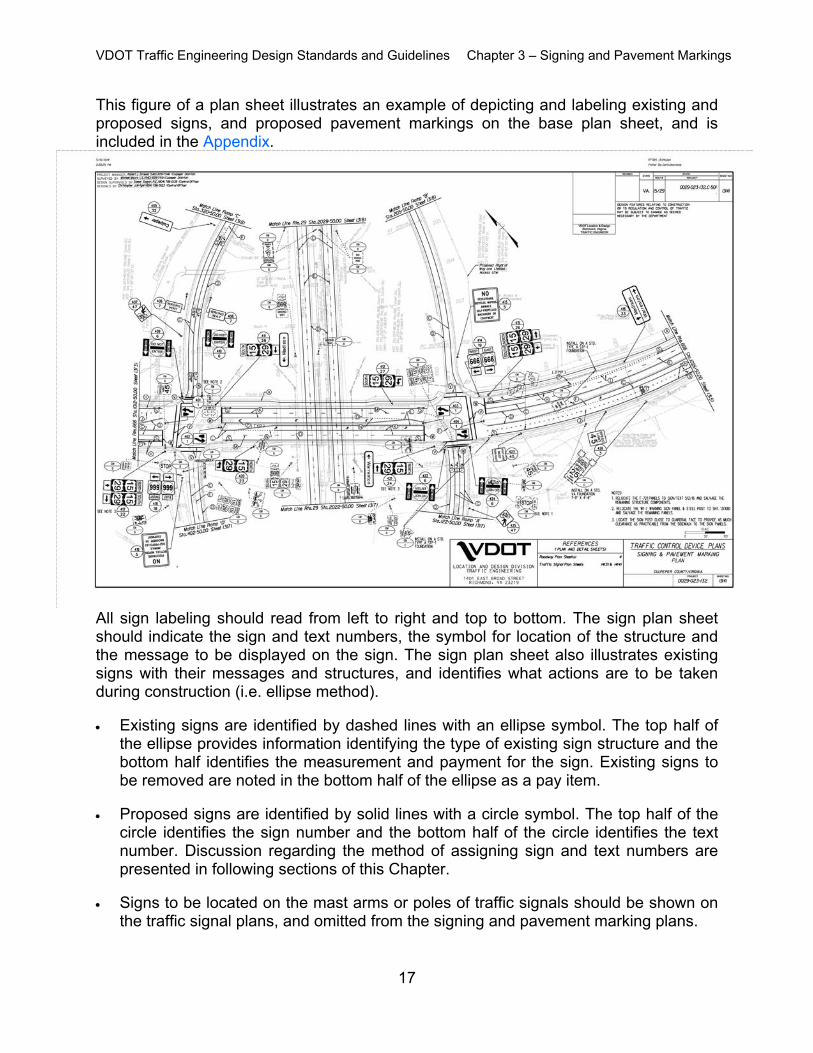
This figure of a plan sheet illustrates an example of depicting and labeling existing and proposed signs, and proposed pavement markings on the base plan sheet, and is included in the Appendix.
All sign labeling should read from left to right and top to bottom. The sign plan sheet should indicate the sign and text numbers, the symbol for location of the structure and the message to be displayed on the sign. The sign plan sheet also illustrates existing signs with their messages and structures, and identifies what actions are to be taken during construction (i.e. ellipse method). Existing signs are identified by dashed lines with an ellipse symbol. The top half of
the ellipse provides information identifying the type of existing sign structure and the bottom half identifies the measurement and payment for the sign. Existing signs to be removed are noted in the bottom half of the ellipse as a pay item.
Proposed signs are identified by solid lines with a circle symbol. The top half of the
circle identifies the sign number and the bottom half of the circle identifies the text number. Discussion regarding the method of assigning sign and text numbers are presented in following sections of this Chapter.
Signs to be located on the mast arms or poles of traffic signals should be shown on
the traffic signal plans, and omitted from the signing and pavement marking plans.
VDOT Traffic Engineering Design Standards and Guidelines Chapter 3 – Signing and Pavement Markings
18
Most signs shown on plan do not typically require detailed location information beyond the distances scaled from the plan, since the location of each sign can easily be scaled from the plan relative to constructed features or property lines. However, in some critical locations, dimensions should be provided between sign posts or panels and nearby features in order to provide the contractor with enough information to match the intent of the sign placement. This may include providing the separation distances between nearby sign posts, the distance of a post from a property line or face of curb, etc. It should be noted that the VDOT Road Design Manual provides other critical information to the contractor relative to sign placement such as the minimum allowable distance from edge of sign panel to the face of curb, in rural and urban conditions, etc.
As part of the pavement marking design, it is important to consider the following:
Gore Markings Crosswalks Intersections (Signalized and Unsignalized) School Zones and Railroad Crossings Traverse Markings Dotted lines, stop bars, parking markings, etc. Pavement Marking Messages Bicycle markings, if any
Any pavement marking details not included in the VDOT Road and Bridge Standards
shall be included in the plan set. Develop the Pavement Marker Layout - Locate and identify the type and color of
pavement markers on the pavement marking plan sheet. Develop the Object Marker Layout - Identify roadway features that require object
markers. Illustrate where the object markers are to be located and label them on the pavement marking plans.
Develop the Delineation Layout- Identify where the roadway geometry requires roadside delineators. Illustrate where the delineators are to be located and label them on the pavement marking plans.
Any marked crosswalks shall follow VDOT’s Guidelines for the Installation of Marked Crosswalks. An engineering study shall be approved by VDOT prior to any installation of marked crosswalks on uncontrolled approaches.
VDOT Traffic Engineering Design Standards and Guidelines Chapter 3 – Signing and Pavement Markings
19
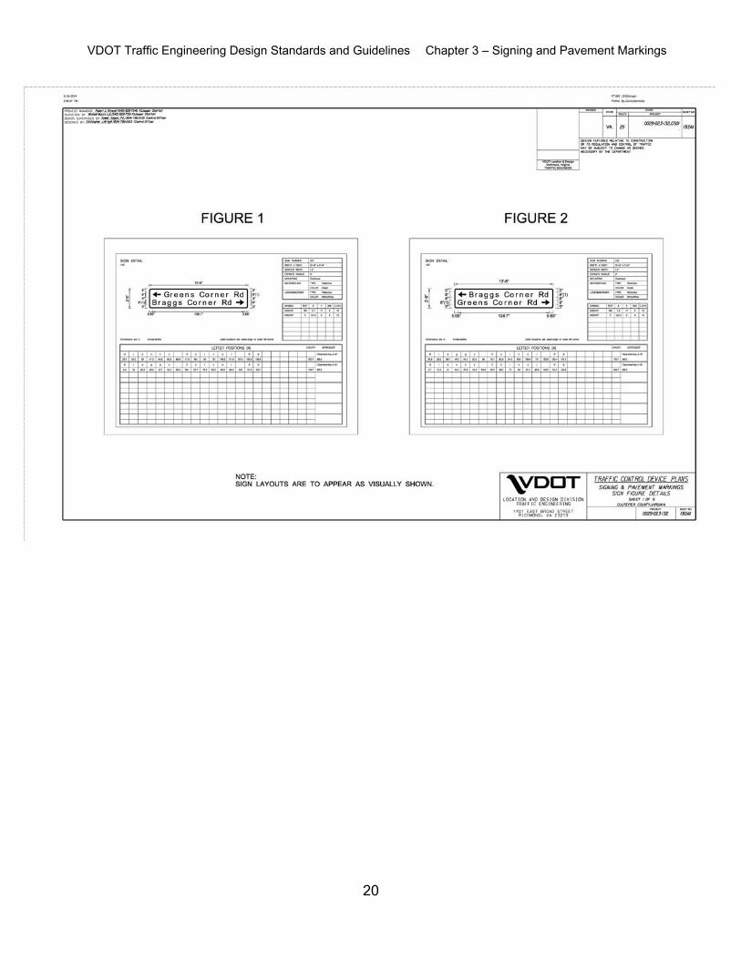
STEP 6- PREPARE SIGN PANEL SPECIAL DETAIL SHEETS Prepare Sign Panel Special Details, as shown in the figure below and in the Appendix. All non-standard MUTCD signs indicated in the Sign Schedule require a Sign Figure
Detail. After determining the appropriate letter size, spacing and margin from the MUTCD, Standard Highway Signs Manual or the Virginia Supplement to the MUTCD, the values are inserted into the GuidSIGN software program to generate the detail, as shown in the figure below. The values can be modified by the designer to accommodate sign sizing.
The dimensions from GuidSIGN need to provide a dimension divisible by six, to be
in accordance with VDOT Standards. Sign Panel Special Detail sheets, designed by the GuidSIGN program, provide sign dimensions and letter positions for sign fabrication on all non-standard signs. Up to six Sign Figure Details can be placed on a Sign Panel Special Detail sheet, if needed. Nonstandard regulatory, warning, or guide signs which use messages, color usage, and/or symbols that are not in the MUTCD or Virginia Supplement to the MUTCD should be submitted to Central Office Traffic Engineering Division for their review.
VDOT Traffic Engineering Design Standards and Guidelines Chapter 3 – Signing and Pavement Markings
20
VDOT Traffic Engineering Design Standards and Guidelines Chapter 3 – Signing and Pavement Markings
21
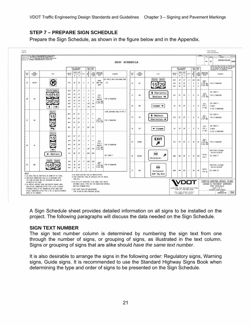
STEP 7 – PREPARE SIGN SCHEDULE Prepare the Sign Schedule, as shown in the figure below and in the Appendix.
A Sign Schedule sheet provides detailed information on all signs to be installed on the project. The following paragraphs will discuss the data needed on the Sign Schedule. SIGN TEXT NUMBER The sign text number column is determined by numbering the sign text from one through the number of signs, or grouping of signs, as illustrated in the text column. Signs or grouping of signs that are alike should have the same text number. It is also desirable to arrange the signs in the following order: Regulatory signs, Warning signs, Guide signs. It is recommended to use the Standard Highway Signs Book when determining the type and order of signs to be presented on the Sign Schedule.
VDOT Traffic Engineering Design Standards and Guidelines Chapter 3 – Signing and Pavement Markings
22
SIGN ASSEMBLY NUMBER The sign assembly number column, is determined by numbering the signs on each plan sheet. The VDOT recommended method is to assign sign assembly numbers in a series starting with the number of the plan sheet that the signs appear on. For example, if the signs being numbered are on Plan Sheet (4), then the signs should be numbered 401 through 499. On Plan Sheet (5) they should be numbered starting at 501, etc. Generally, the signs should be numbered in order from left to right, and then top to bottom to make it easier to locate sign placements from the sign schedule. Standard Number The standard number column is derived from the MUTCD, Standard Highway Signs Manual or the Virginia Supplement to the MUTCD. If a standard number is not applicable, the word “SPECIAL” is indicated. Panel Size The panel size column is determined from the GuidSIGN Software Program, Standard Highway Signs Manual, MUTCD, or the Virginia supplement to the MUTCD. Quantity The quantity column for each sign or grouping of signs for the entire plan set is determined and identified in the Sign Schedule. Sign Area The sign area column is the square feet of the sign panel for each sign text number. Sign Structure Standard The sign structure standard column identifies the type of structure [i.e. Overhead, Square Tube Post, Type VA, Type VIA, steel or wood (size and type)]. Remarks The remarks column, as shown in the figure, denotes figure references, special directions or intentions that further describe the construction requirement of the signs.
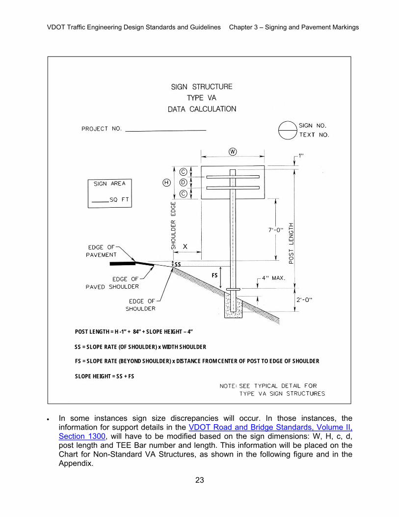
STEP 8- PREPARE TYPE VA SIGN STRUCTURE DETAIL
Instructions to determine the type and details for Type VA Sign Structures are provided in the latest version of the VDOT Road and Bridge Standards. Additionally, support and foundation detail standards are provided under SSP-VA. The type and details for Non-Standard Type VA Sign Structures can be determined
using the Sign Structure Type VA Data Calculation, as shown in the following figure.
VDOT Traffic Engineering Design Standards and Guidelines Chapter 3 – Signing and Pavement Markings
23
In some instances sign size discrepancies will occur. In those instances, the
information for support details in the VDOT Road and Bridge Standards, Volume II, Section 1300, will have to be modified based on the sign dimensions: W, H, c, d, post length and TEE Bar number and length. This information will be placed on the Chart for Non-Standard VA Structures, as shown in the following figure and in the Appendix.
X
SS = SLOPE RATE (OF SHOULDER) x WIDTH SHOULDER
POST LENGTH = H -1” + 84” + SLOPE HEIGHT – 4”
SLOPE HEIGHT = SS + FS
FS = SLOPE RATE (BEYOND SHOULDER) x DISTANCE FROM CENTER OF POST TO EDGE OF SHOULDER
SS
FS
VDOT Traffic Engineering Design Standards and Guidelines Chapter 3 – Signing and Pavement Markings
24
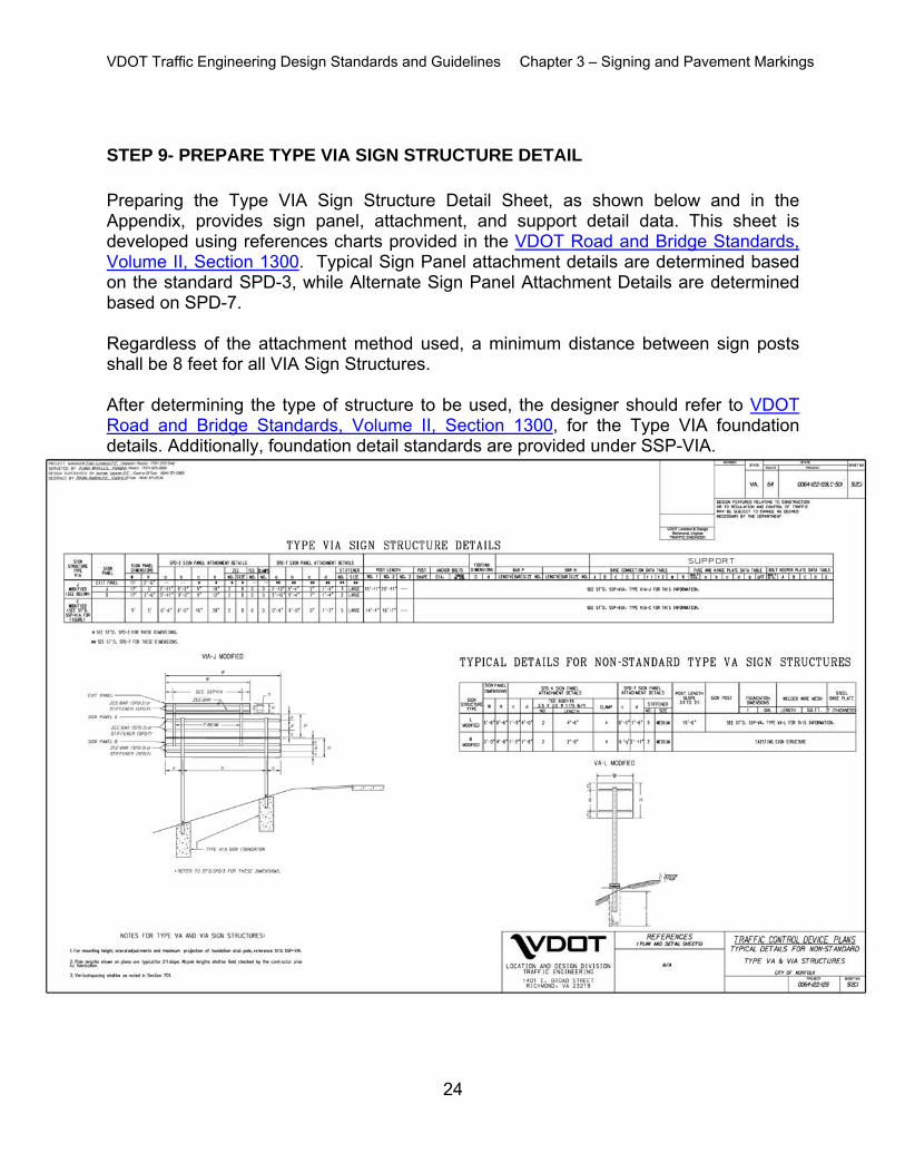
STEP 9- PREPARE TYPE VIA SIGN STRUCTURE DETAIL Preparing the Type VIA Sign Structure Detail Sheet, as shown below and in the Appendix, provides sign panel, attachment, and support detail data. This sheet is developed using references charts provided in the VDOT Road and Bridge Standards, Volume II, Section 1300. Typical Sign Panel attachment details are determined based on the standard SPD-3, while Alternate Sign Panel Attachment Details are determined based on SPD-7. Regardless of the attachment method used, a minimum distance between sign posts shall be 8 feet for all VIA Sign Structures. After determining the type of structure to be used, the designer should refer to VDOT Road and Bridge Standards, Volume II, Section 1300, for the Type VIA foundation details. Additionally, foundation detail standards are provided under SSP-VIA.
VDOT Traffic Engineering Design Standards and Guidelines Chapter 3 – Signing and Pavement Markings
25
The VIA sign structure type is determined by matching the height and width of the specific sign panel under consideration to those outlined in the Sign Structure Detail Chart.
Most sign panel sizes on the project will not have dimensions exactly as shown on the Sign Structure Detail Chart. When the sign panel dimensions vary from the Sign Structure Detail Chart, the following subsections will provide design strategies to be used to modify the sign structure type and determine the data values for the attachment details and supports:
Width Discrepancy Locate the width of sign panel under consideration within smallest possible range of widths in the Sign Structure Detail Chart.
If the sign panel width is less than midway between the two widths on the chart, select the lower value within the range and use all data values except the “a” and “b” dimensions of the attachment detail.
If the sign panel width is midway or more between the two widths on the chart, select the greater value within the range and use all data values except the “a” and “b” dimensions of the attachment detail.
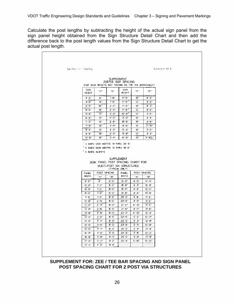
The attachment detail dimensions for “a” and “b” are determined using the Supplement Sign Panel Post Spacing Chart for Multi-Post VIA Structures, as shown in the following table and in the Appendix. Use the actual sign panel width to determine “a” and “b” dimensions and interpolate, if necessary.
Height Discrepancy Locate the height of the sign panel under consideration within the smallest possible range of heights in the Sign Structure Detail Chart.
If the sign panel height is more than 6-inches greater than the smaller height dimension within the chart range, select the larger height value within the chart range and use all data except the “c” and “d” of the attachment detail and the number of Zee / Tee Bars. Use the Supplement Zee / Tee bar Spacing Chart, as shown in the following table and in the Appendix, as well as the Sign Structure Detail Chart in the VDOT Road and Bridge Standards, Volume II, Section 1300 to determine the “c” and “d” dimensions and number of the bars.
Calculate the post lengths by subtracting the height of the actual sign panel from the sign panel height obtained from the Sign Structure Detail Chart and then subtract the difference from the post length values from the Sign Structure Detail Chart to get the actual post length.
If the sign height is 6-inches or less than the smaller height dimension within the chart range, use the smaller height dimension within the chart range to determine all data except the “c” and “d” post lengths and number of bars. Use the Supplement Zee / Tee bar Spacing Chart and the Sign Structure Detail Chart to determine the “c” and “d” dimensions and number of the bars.
VDOT Traffic Engineering Design Standards and Guidelines Chapter 3 – Signing and Pavement Markings
26
Calculate the post lengths by subtracting the height of the actual sign panel from the sign panel height obtained from the Sign Structure Detail Chart and then add the difference back to the post length values from the Sign Structure Detail Chart to get the actual post length.
SUPPLEMENT FOR: ZEE / TEE BAR SPACING AND SIGN PANEL POST SPACING CHART FOR 2 POST VIA STRUCTURES
VDOT Traffic Engineering Design Standards and Guidelines Chapter 3 – Signing and Pavement Markings
27
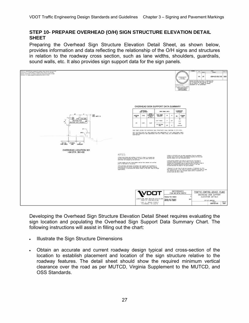
STEP 10- PREPARE OVERHEAD (O/H) SIGN STRUCTURE ELEVATION DETAIL SHEET Preparing the Overhead Sign Structure Elevation Detail Sheet, as shown below, provides information and data reflecting the relationship of the O/H signs and structures in relation to the roadway cross section, such as lane widths, shoulders, guardrails, sound walls, etc. It also provides sign support data for the sign panels.
Developing the Overhead Sign Structure Elevation Detail Sheet requires evaluating the sign location and populating the Overhead Sign Support Data Summary Chart. The following instructions will assist in filling out the chart: Illustrate the Sign Structure Dimensions Obtain an accurate and current roadway design typical and cross-section of the
location to establish placement and location of the sign structure relative to the roadway features. The detail sheet should show the required minimum vertical clearance over the road as per MUTCD, Virginia Supplement to the MUTCD, and OSS Standards.
VDOT Traffic Engineering Design Standards and Guidelines Chapter 3 – Signing and Pavement Markings
28
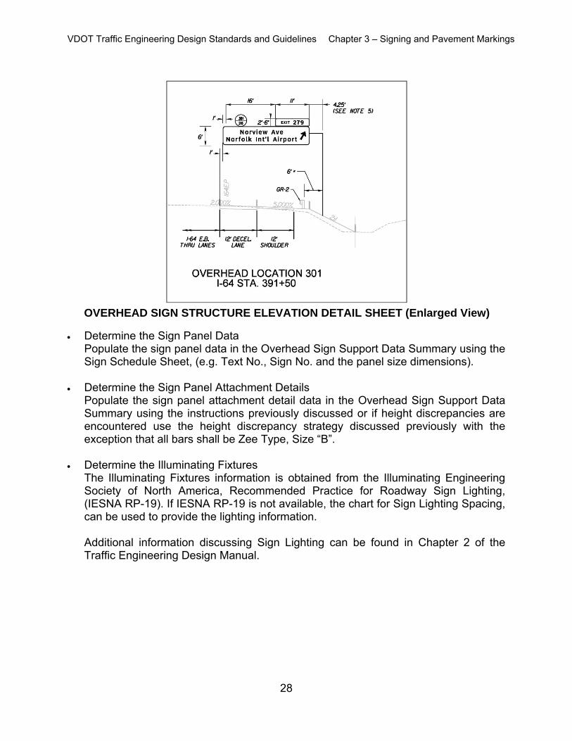
Determine the Sign Panel Data
Populate the sign panel data in the Overhead Sign Support Data Summary using the Sign Schedule Sheet, (e.g. Text No., Sign No. and the panel size dimensions).
Determine the Sign Panel Attachment Details
Populate the sign panel attachment detail data in the Overhead Sign Support Data Summary using the instructions previously discussed or if height discrepancies are encountered use the height discrepancy strategy discussed previously with the exception that all bars shall be Zee Type, Size “B”.
Determine the Illuminating Fixtures
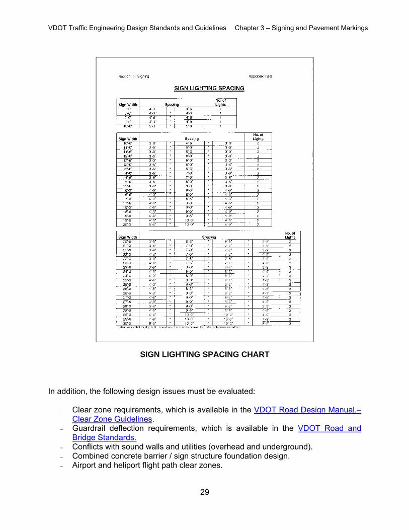
The Illuminating Fixtures information is obtained from the Illuminating Engineering Society of North America, Recommended Practice for Roadway Sign Lighting, (IESNA RP-19). If IESNA RP-19 is not available, the chart for Sign Lighting Spacing, can be used to provide the lighting information. Additional information discussing Sign Lighting can be found in Chapter 2 of the Traffic Engineering Design Manual.
VDOT Traffic Engineering Design Standards and Guidelines Chapter 3 – Signing and Pavement Markings
29
In addition, the following design issues must be evaluated:
Clear zone requirements, which is available in the VDOT Road Design Manual,– Clear Zone Guidelines.
Guardrail deflection requirements, which is available in the VDOT Road and Bridge Standards.
Conflicts with sound walls and utilities (overhead and underground). Combined concrete barrier / sign structure foundation design. Airport and heliport flight path clear zones.
SIGN LIGHTING SPACING CHART
VDOT Traffic Engineering Design Standards and Guidelines Chapter 3 – Signing and Pavement Markings
30
Geotechnical issues with soil at candidate location. Additional Overhead Sign Structure Considerations
Cantilever arm lengths should not exceed the maximum allowable length as per IIM-LD-250. The edge of the sign panel should extend 1-foot beyond the end of the arm.
Span sign structures should not exceed the maximum allowable span length as per IIM-LD-250.
Butterfly sign structures – the edge of the sign panel should extend 1-foot beyond the edge of the arm on both sides. The designer should verify that adequate ROW exists for both the sign support and the far edge of the sign. When lighting is required on overhead signing it will be necessary to meet with a local power representative to determine the power source routing and identify power pole numbers from which the power would be supplied to the service. On some projects this will be coordinated with the roadway lighting. Others will require obtaining separate power sources and providing the wire routing along with wire sizing and junction box locations. Additional information discussing locating and furnishing the power source locations can be found in the Roadway Lighting Chapter.
For span sign structures, the designer should consider the possibility of additional signs being added to the span structure in future years. If so, notes or details should be added to the plans which depict the potential future signs and require the Contractor to design the sign structure to accommodate that future loading. If overhead utilities are present within the vicinity of the sign structure, the designer should verify that the structure will not violate the required OSHA/NEC minimum clearance.
STEP 11 – PREPARE GENERAL NOTES, INDEX OF SHEETS, SIGN LEGEND, AND PAVEMENT MARKING LEGEND
General Notes
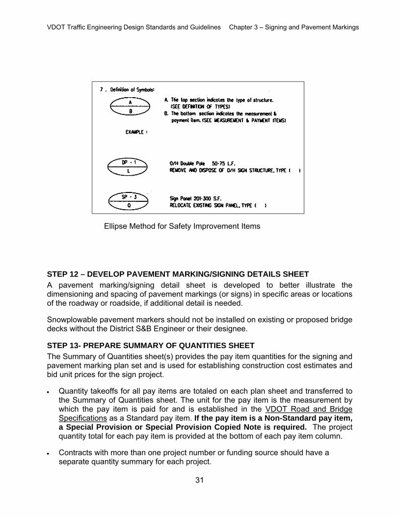
Provides general information related to the sign plans and applies throughout the project plan set. An important component of the General Notes is the definition of symbols.
The ellipse symbol is used on the plan sheet to provide instruction on the action to be taken for an existing sign and / or sign structure.
VDOT Traffic Engineering Design Standards and Guidelines Chapter 3 – Signing and Pavement Markings
31
STEP 12 – DEVELOP PAVEMENT MARKING/SIGNING DETAILS SHEET A pavement marking/signing detail sheet is developed to better illustrate the dimensioning and spacing of pavement markings (or signs) in specific areas or locations of the roadway or roadside, if additional detail is needed. Snowplowable pavement markers should not be installed on existing or proposed bridge decks without the District S&B Engineer or their designee.
STEP 13- PREPARE SUMMARY OF QUANTITIES SHEET The Summary of Quantities sheet(s) provides the pay item quantities for the signing and pavement marking plan set and is used for establishing construction cost estimates and bid unit prices for the sign project. Quantity takeoffs for all pay items are totaled on each plan sheet and transferred to
the Summary of Quantities sheet. The unit for the pay item is the measurement by which the pay item is paid for and is established in the VDOT Road and Bridge Specifications as a Standard pay item. If the pay item is a Non-Standard pay item, a Special Provision or Special Provision Copied Note is required. The project quantity total for each pay item is provided at the bottom of each pay item column.
Contracts with more than one project number or funding source should have a