Chapter 3Twenty-Three Kilometres of SuperfluidHelium Cryostats for the SuperconductingMagnets of the Large Hadron Collider(LHC)
Philippe Lebrun
Abstract The Large Hadron Collider (LHC) at CERN is the world’s largest sci-entific instrument. The 1600 “high-field” superconducting magnets that make upthe 23 km circumference accelerator ring represent the largest use of superfluidhelium (He II) to date. This chapter describes the design evolution of the LHCmagnet cryostats with particular emphasis on the He II cooling system, thermalinsulation system and structural supports. Prototype testing, series production,installation and commissioning of these cryostats is also discussed. Numerousfigures and tables illustrate the cryostat and present performance results.
3.1 The LHC and Its Cryogenic System
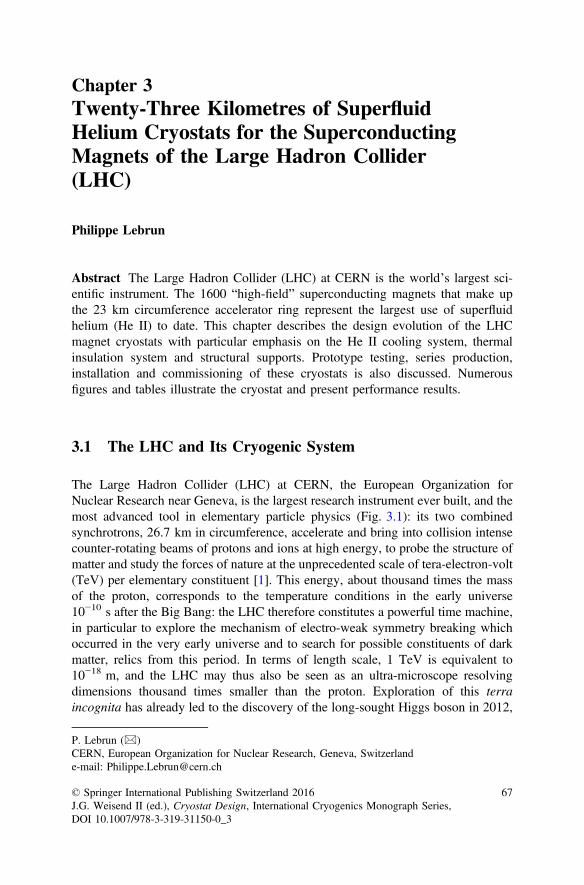
The Large Hadron Collider (LHC) at CERN, the European Organization forNuclear Research near Geneva, is the largest research instrument ever built, and themost advanced tool in elementary particle physics (Fig. 3.1): its two combinedsynchrotrons, 26.7 km in circumference, accelerate and bring into collision intensecounter-rotating beams of protons and ions at high energy, to probe the structure ofmatter and study the forces of nature at the unprecedented scale of tera-electron-volt(TeV) per elementary constituent [1]. This energy, about thousand times the massof the proton, corresponds to the temperature conditions in the early universe10−10 s after the Big Bang: the LHC therefore constitutes a powerful time machine,in particular to explore the mechanism of electro-weak symmetry breaking whichoccurred in the very early universe and to search for possible constituents of darkmatter, relics from this period. In terms of length scale, 1 TeV is equivalent to10−18 m, and the LHC may thus also be seen as an ultra-microscope resolvingdimensions thousand times smaller than the proton. Exploration of this terraincognita has already led to the discovery of the long-sought Higgs boson in 2012,
P. Lebrun (&)CERN, European Organization for Nuclear Research, Geneva, Switzerlande-mail: [email protected]
and is continuing with precision measurement of its properties as well as withsearch for new physics, “beyond the Standard Model”.
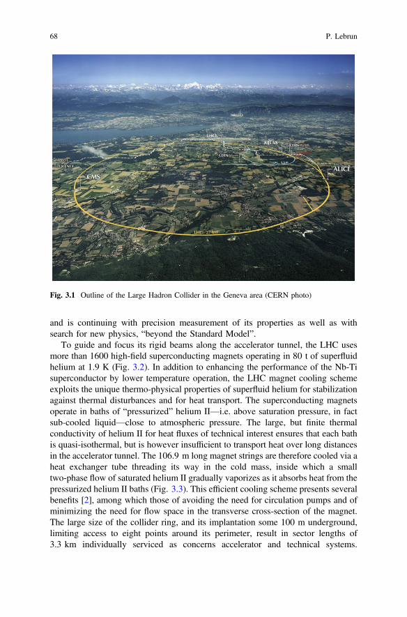
To guide and focus its rigid beams along the accelerator tunnel, the LHC usesmore than 1600 high-field superconducting magnets operating in 80 t of superfluidhelium at 1.9 K (Fig. 3.2). In addition to enhancing the performance of the Nb-Tisuperconductor by lower temperature operation, the LHC magnet cooling schemeexploits the unique thermo-physical properties of superfluid helium for stabilizationagainst thermal disturbances and for heat transport. The superconducting magnetsoperate in baths of “pressurized” helium II—i.e. above saturation pressure, in factsub-cooled liquid—close to atmospheric pressure. The large, but finite thermalconductivity of helium II for heat fluxes of technical interest ensures that each bathis quasi-isothermal, but is however insufficient to transport heat over long distancesin the accelerator tunnel. The 106.9 m long magnet strings are therefore cooled via aheat exchanger tube threading its way in the cold mass, inside which a smalltwo-phase flow of saturated helium II gradually vaporizes as it absorbs heat from thepressurized helium II baths (Fig. 3.3). This efficient cooling scheme presents severalbenefits [2], among which those of avoiding the need for circulation pumps and ofminimizing the need for flow space in the transverse cross-section of the magnet.The large size of the collider ring, and its implantation some 100 m underground,limiting access to eight points around its perimeter, result in sector lengths of3.3 km individually serviced as concerns accelerator and technical systems.
Fig. 3.1 Outline of the Large Hadron Collider in the Geneva area (CERN photo)
68 P. Lebrun
The LHC ring is cooled by eight large-capacity cryogenic plants, each normallycooling a 3.3 km sector, but able to serve two adjacent sectors and thus provideredundancy at partial load. This requires distributing and recovering helium flows atdifferent temperatures in the access shafts and along the machine tunnel over lengthsof up to 3.3 km, by means of a compound cryogenic distribution line running along
Fig. 3.2 The LHC cryomagnets installed in the tunnel (CERN photo)
Saturated He II, flowing
Pressurized He II, static
Heat exchanger tube
SC magnet Helium vessel SC bus-bar connection
Fig. 3.3 Principle of the superfluid helium cooling scheme of the LHC magnets
3 Twenty-Three Kilometres of Superfluid Helium … 69
the magnets and feeding each 106.9 m string in parallel. Each cryogenic plantprovides a mix of liquefaction and refrigeration duties at 50–75 K and 4.5–20 K,amounting to an equivalent entropic capacity of 18 kW at 4.5 K. It is complementedat its cold end by a 1.8 K stage producing up to 2.4 kW of refrigeration power, bymeans of multi-stage sub-atmospheric compression using cold hydrodynamic androom-temperature volumetric compressors. Precooling the 37,500 t cold mass downto about 100 K is achieved by vaporization of some 10,000 t liquid nitrogen. Liquidnitrogen is otherwise not used in the system. 21,300 sensors monitor the machinecryogenics, while 4700 analog control loops ensure its operation. The cryogenicsystem of the LHC is described in Ref. [3].
In the following we tell the LHC cryostat story, approximately followingchronological order, from the first studies and experimental work which enabled toestablish the feasibility of such a large, novel superfluid helium system, to theseveral generations of prototypes meeting the evolution of machine configuration,their industrialization, series production and assembly, installation and intercon-nection in the tunnel, commissioning and operational experience. Focus is on theeight, 2818 m long continuous cold strings of the LHC arcs, containing in particularthe 1232 dipole magnet cryostats (each 15 m in length) which constitute 85 % ofthe cold length and therefore drive the design, construction and industrializationchoices, as well as the overall performance and cost of the system.
3.2 Feasibility of a Large DistributedSuperfluid Helium System
The first approach to a large hadron collider to be installed in the existing tunnelhousing the LEP collider, was based on twin-aperture dipole magnets using “cos h”coils made of Nb3Sn superconductor operated in baths of normal helium at 4.5 K,to produce a bending field around 10 T [4]. The study included the conceptualdesign of the corresponding cryogenic system, including cryostat simplifiedcross-section. It identified the main requirements and boundary conditions oflarge-capacity refrigerators at 4.5 K, thermal shielding at around 80 K, cryogenicfluid distribution along the 3.3 km sectors, cryogen storage, cooldown of the largemagnet mass, quench handling and recovery and underground safety.
Soon after this it became clear that, in view of the limited availability, high costand technical difficulty of implementing Nb3Sn superconductors in acceleratormagnets, the alternative of operating the more conventional Nb-Ti superconductingalloy at lower temperature in superfluid helium—to boost its current-carryingcapacity at high field—should also be explored. This technique, pioneered at CEAGrenoble and first applied to cool high-field magnets for condensed-matter physics(the Grenoble High-Field Magnet) and nuclear fusion research (the TORE SUPRAtokamak at CEA Cadarache) [5], had however never been applied to the magnetsand distributed configuration of a large circular accelerator. It clearly appeared that
70 P. Lebrun
the prime feasibility issues to be investigated were the management of heat loads(and thus the design of a cryostat meeting the required thermal performance) andthe cryogenic distribution scheme—the latter also impacting the cryostat design toincorporate the cryogenic pipelines. A preliminary study of a superfluid heliumcryogenic system for the LHC was then conducted [6].
A novel feature of the LHC with respect to previous superconducting acceler-ators is that the “static” heat loads, i.e. the heat in-leaks to the cold mass and othercryogenic components of the machine, represent only a fraction of the total. Thelarge excitation currents of the magnets—12 kA for the LHC dipoles—induceresistive heating in the numerous non-superconducting joints between the windinglayers, between the coils and between the magnets in a string: this additional“dynamic” heat load necessarily ends up into the helium bath at the lowest tem-perature level and must therefore be contained by a tight specification on themaximum joint resistance (typically lower than 1 nX per joint). Moreover, thecirculation of intense particle beams in the accelerator rings also induces dynamicheat loads, through several processes such as dissipation of beam image currents inthe resistive wall of the beam pipes, synchrotron radiation from the beams (in theUV range for LHC protons) and particle losses from the beam halo. While the latterproduce cascades of secondary particles eventually depositing their energy into themagnet cold mass, the power of the other two processes may be intercepted athigher temperature in order to reduce its thermodynamic impact on the refrigerationsystem. This is the primary function devoted to the beam screens, the concept ofwhich was introduced for the first time in the study. Today, beam screens cooled bysupercritical helium between 5 and 20 K equip the LHC magnets and limit the heatload to the 1.9 K level to acceptable values; they also perform several otheressential functions [7], in particular that of a distributed cryopump maintaining agood level of dynamic vacuum in the beam pipes, and their elaborate design istherefore the optimized result of a complex process involving several domains ofaccelerator physics and technology (Fig. 3.4). Pre-design of the cryostat featuring a90 K thermal shield, non-metallic supports of the cold mass with heat intercepts at90 and 4.5 K, multilayer reflective insulation around the cold mass, and integratingcryogenic distribution pipelines, gave an estimated heat in-leak at 1.9 K of0.15 W/m. Containing the dissipation in the resistive joints to 0.05 W/m andintroducing the beam screens to intercept most of the beam-induced heat loadsyielded a total steady-state budget of 0.2 W/m at 1.9 K, to be compared with0.9 W/m at 4.5 K for a normal helium cryostat in absence of beam screen. Theconclusion of this preliminary study was that a superfluid helium cryogenic systemfor the LHC, including magnet cryostat and distribution scheme, appeared possible,though more complex than one at normal helium temperature.
The following years saw the refinement of such studies, particularly concerningthe cryogenic distribution scheme and the assessment of dynamic heat loads, but thecryostat design concept (Fig. 3.5) and estimated performance of 0.15 W/m at 1.9 Kwere essentially confirmed [8]. The addition of a complete shield at 5 K sur-rounding the cold mass allowed—in principle—to reduce the residual gas con-duction to the cold mass and thus the dependence of total heat load on the quality of
3 Twenty-Three Kilometres of Superfluid Helium … 71
Pumping slots
Reduce beam-inducedcryogenic loads
Increase developmenttime of transverse
resistive-wall instability
Resist eddy-currentforces at magnet quench
Preserve field quality in magnet aperture
Maintain good beamvacuum
Limit development of electron cloud
Intercept synchrotron radiation
Limit resistive wallimpedance
Limit residual heat loadto cold mass
Structural material withhigh resistivity
Low-permeabilitymaterials
Provide pumping fromshielded cold surface
Limit reflectivity and SEY of beam screen surface
Low-conduction supports
High-conductivity copperplating
Cooling at lowtemperature
Austenitic stainless steelstructure
Avoid temperaturesfavoring desorption of common gas species
Sawtooth absorber
Beam scrubbing
FUNCTION PROCESS DESIGN FEATURE
Fig. 3.4 Functional design map of beam screen for particle accelerator
Fig. 3.5 Transversecross-section of conceptualcryostat housing LHCtwin-aperture dipole magnetat 1.9 K. 1 magnet coils;2 magnet collars; 3 magnetyoke; 4 magnet shrinkingcylinder and helium vessel;5 beam screen; 6 shield at5 K; 7 MLI insulated shield at80 K; 8 non-metallic supportpost; 9 vacuum vessel;A helium II heat exchangertube; B–F cryogenicdistribution and recovery linesat 1.9, 5 and 80 K
72 P. Lebrun
the insulation vacuum. Assessment of the practical benefit of this additional featureled to several iterations discussed in the following.
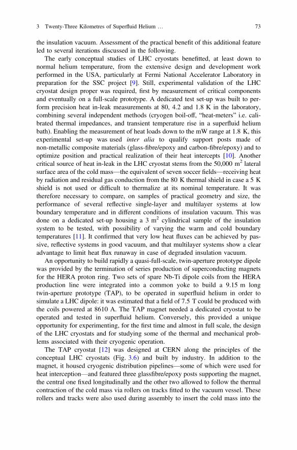
The early conceptual studies of LHC cryostats benefitted, at least down tonormal helium temperature, from the extensive design and development workperformed in the USA, particularly at Fermi National Accelerator Laboratory inpreparation for the SSC project [9]. Still, experimental validation of the LHCcryostat design proper was required, first by measurement of critical componentsand eventually on a full-scale prototype. A dedicated test set-up was built to per-form precision heat in-leak measurements at 80, 4.2 and 1.8 K in the laboratory,combining several independent methods (cryogen boil-off, “heat-meters” i.e. cali-brated thermal impedances, and transient temperature rise in a superfluid heliumbath). Enabling the measurement of heat loads down to the mW range at 1.8 K, thisexperimental set-up was used inter alia to qualify support posts made ofnon-metallic composite materials (glass-fibre/epoxy and carbon-fibre/epoxy) and tooptimize position and practical realization of their heat intercepts [10]. Anothercritical source of heat in-leak in the LHC cryostat stems from the 50,000 m2 lateralsurface area of the cold mass—the equivalent of seven soccer fields—receiving heatby radiation and residual gas conduction from the 80 K thermal shield in case a 5 Kshield is not used or difficult to thermalize at its nominal temperature. It wastherefore necessary to compare, on samples of practical geometry and size, theperformance of several reflective single-layer and multilayer systems at lowboundary temperature and in different conditions of insulation vacuum. This wasdone on a dedicated set-up housing a 3 m2 cylindrical sample of the insulationsystem to be tested, with possibility of varying the warm and cold boundarytemperatures [11]. It confirmed that very low heat fluxes can be achieved by pas-sive, reflective systems in good vacuum, and that multilayer systems show a clearadvantage to limit heat flux runaway in case of degraded insulation vacuum.
An opportunity to build rapidly a quasi-full-scale, twin-aperture prototype dipolewas provided by the termination of series production of superconducting magnetsfor the HERA proton ring. Two sets of spare Nb-Ti dipole coils from the HERAproduction line were integrated into a common yoke to build a 9.15 m longtwin-aperture prototype (TAP), to be operated in superfluid helium in order tosimulate a LHC dipole: it was estimated that a field of 7.5 T could be produced withthe coils powered at 8610 A. The TAP magnet needed a dedicated cryostat to beoperated and tested in superfluid helium. Conversely, this provided a uniqueopportunity for experimenting, for the first time and almost in full scale, the designof the LHC cryostats and for studying some of the thermal and mechanical prob-lems associated with their cryogenic operation.
The TAP cryostat [12] was designed at CERN along the principles of theconceptual LHC cryostats (Fig. 3.6) and built by industry. In addition to themagnet, it housed cryogenic distribution pipelines—some of which were used forheat interception—and featured three glassfibre/epoxy posts supporting the magnet,the central one fixed longitudinally and the other two allowed to follow the thermalcontraction of the cold mass via rollers on tracks fitted to the vacuum vessel. Theserollers and tracks were also used during assembly to insert the cold mass into the
3 Twenty-Three Kilometres of Superfluid Helium … 73
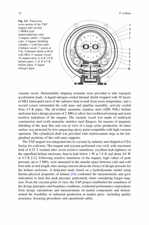
vacuum vessel. Demountable shipping restraints were provided to take transportacceleration loads. A liquid-nitrogen cooled thermal shield wrapped with 30 layersof MLI intercepted most of the radiative heat in-leak from room temperature, and asecond screen surrounded the cold mass and pipeline assembly, actively cooledfrom 4.5 K pipes. The all-welded, austenitic stainless steel (AISI 304L) heliumenclosure had a design pressure of 2 MPa to allow fast cooldown/warmup and resistresistive transitions of the magnet. The vacuum vessel was made of unalloyedconstruction steel (with austenitic stainless steel flanges), for reasons of magneticshielding of the stray flux and cost in view of a large series production. Its innersurface was protected by low-outgassing epoxy paint compatible with high-vacuumoperation. The cylindrical shell was provided with reinforcement rings at the lon-gitudinal positions of the cold mass supports.
The TAP magnet was integrated into its cryostat by industry and shipped to CEASaclay for cold tests. The magnet and cryostat performed very well, with maximumfield of 8.25 T reached after seven resistive transitions, excellent leak-tightness ofthe superfluid helium enclosure, heat in-leak below 1 W at 1.8 K and about 4.6 Wat 4.5 K [13]. Following resistive transitions of the magnet, high values of peakpressure, up to 3 MPa, were measured in the annular space between coils and coldbore tube at mid-length, thus raising concern about the choice of design pressure forthe helium enclosure. A dedicated study based on a hydrodynamic model usingthermo-physical properties of helium [14] confirmed the measurements and gaveindications to limit this peak pressure, particularly when considering longer mag-nets. From the cryostat point of view, the TAP project established the soundness ofthe design principles and boundary conditions, confirmed performance expectationsfrom design calculations and measurements on partial components and demon-strated the feasibility of industrial production at market price—including qualityassurance, licencing procedures and operational safety.
Fig. 3.6 Transversecross-section of the TAPmagnet and cryostat.1 HERA-typesuperconducting coils;2 magnet collars; 3 magnetyoke; 4 magnet shrinkingcylinder; 5 cold bore tube;6 helium vessel; 7 screen at5 K; 8 thermal shield at 80 Kwith MLI; 9 vacuum vessel;10 support post; A & B 1.8 Khelium pipes; C & D 4.5 Khelium pipes; E liquidnitrogen pipes
74 P. Lebrun
3.3 Prototype Cryostats and String Tests
Based on the previous experience, a small series of cryostats were designed atCERN and procured from industry to house the first generation of 10 m longprototype dipole magnets, to be tested individually and later connected and oper-ated in a string. The cryostats also had to accommodate the cryogenic distributionpipework sized for feeding a full LHC sector. Design requirements included heatin-leaks meeting the allowed thermal budget at the three temperature levels orranges in the LHC cryogenic system (50–75 K, 4.5–20 K and 1.9 K), provision ofa stable, precise and reproducible mechanical support for the magnet, withstandingof thermal and mechanical transients associated with rapid cooldown and magnetresistive transitions, as well as all possible failure modes. Technical solutionsadapted to large series production were favoured.
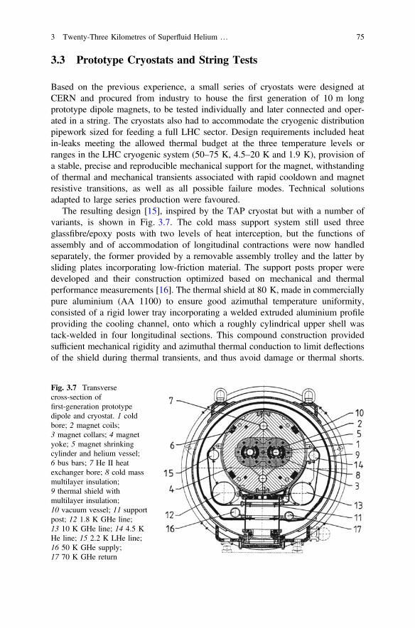
The resulting design [15], inspired by the TAP cryostat but with a number ofvariants, is shown in Fig. 3.7. The cold mass support system still used threeglassfibre/epoxy posts with two levels of heat interception, but the functions ofassembly and of accommodation of longitudinal contractions were now handledseparately, the former provided by a removable assembly trolley and the latter bysliding plates incorporating low-friction material. The support posts proper weredeveloped and their construction optimized based on mechanical and thermalperformance measurements [16]. The thermal shield at 80 K, made in commerciallypure aluminium (AA 1100) to ensure good azimuthal temperature uniformity,consisted of a rigid lower tray incorporating a welded extruded aluminium profileproviding the cooling channel, onto which a roughly cylindrical upper shell wastack-welded in four longitudinal sections. This compound construction providedsufficient mechanical rigidity and azimuthal thermal conduction to limit deflectionsof the shield during thermal transients, and thus avoid damage or thermal shorts.
Fig. 3.7 Transversecross-section offirst-generation prototypedipole and cryostat. 1 coldbore; 2 magnet coils;3 magnet collars; 4 magnetyoke; 5 magnet shrinkingcylinder and helium vessel;6 bus bars; 7 He II heatexchanger bore; 8 cold massmultilayer insulation;9 thermal shield withmultilayer insulation;10 vacuum vessel; 11 supportpost; 12 1.8 K GHe line;13 10 K GHe line; 14 4.5 KHe line; 15 2.2 K LHe line;16 50 K GHe supply;17 70 K GHe return
3 Twenty-Three Kilometres of Superfluid Helium … 75
The actively cooled 4.5 K screen surrounding the cold mass of the TAP cryostatwas replaced here by a 10-layer blanket of MLI, partially thermalized onto the4.5 K lines but insulated from the cold mass and 2 K lines by polyester spacers.Another, important novelty with respect to the TAP cryostat was the first engi-neering study and optimization of magnet and cryostat interconnection. To maxi-mize the magnet filling factor of the machine and thus the beam energy reach, theinterconnection space must be kept as short as possible, while allowing to reliablyperform, inspect and test some 14 orbital welds joining 11 pipes. Space for auto-matic orbital welding and cutting machines, as well as for “clam shells” for localleak-testing of welds, was taken into account. The interconnection also includes allbellows accommodating construction and alignment tolerances, as well differentialthermal contractions and displacements occurring in all possible phases of opera-tion, including failure modes (as a reminder, the LHC cold mass shrinks by some80 m in perimeter upon cooldown). Bellows specifications, including travel,misalignments, maximum rigidity and fatigue lifetime were established, pointing tohydro-formed multiply construction with external shells against buckling whereneeded. Samples were procured from several bellows manufacturers and exten-sively tested, thus providing a qualified industrial basis for future seriesprocurement.
The design of the prototype dipole cryostat was adapted to house the mainquadrupole, chromaticity sextupole and corrector magnets, beam position monitorsand local cryogenic equipment as well as a vacuum barrier segmenting the insu-lation vacuum, all included in a so-called short-straight-section cryostat [17], and aprototype was built and tested.
In parallel with these activities, preparation was made to perform cryogenic testsof the magnets and cryostats. A 7200 m2 test hall already equipped with a 6 kW at4.5 K cryogenic refrigerator was further provided with a low-pressure heliumpumping unit capable of 6 g/s at 1 kPa, upgradeable to 18 g/s with the addition of acold booster compressor. Cooldown and warmup units, each providing up to120 kW down to 100 K by vaporization of liquid nitrogen [18] were installed. Thetest station was planned to develop in a modular way following the ramp-up ofseries production, with up to twelve parallel test benches, the first two of whichwere commissioned to test prototypes [19]. Each bench, equipped with 18 kAcurrent leads, could be operated independently of the others, only sharing—whenand as much as needed—the common facilities such as normal liquid heliumsupply, pumping capacity at 1 kPa and gaseous helium flow for cooldown andwarmup.
At the same time it was noted that precision thermal measurements on cryostatsmounted on magnet test benches would be difficult to perform, due to parasitic heatloads (in particular the comparatively high heat in-leak coming from theanti-cryostats installed in the magnet apertures to perform magnetic measurements)as well as to schedule interference (reaching thermal steady-state requires longstabilization time incompatible with magnet turnaround on test benches). It wastherefore decided to build a full-scale thermal model [20] from a 10 m prototypecryostat equipped with a dummy cold mass and finely instrumented. The cryostat
76 P. Lebrun
thermal model could be operated independently of the magnet tests station,allowing to vary parameters such as insulation vacuum and temperature levels, andproviding precision of ±0.03 W at 1.8 K, ±0.1 W at 5–20 K and ±3 W at 50–75 K. Heat load measurements in nominal operating conditions on the thermalmodel showed excellent agreement with calculated values [21]. Moreover, severaloff-design runs enabled to measure the sensitivity of the cryostat heat in-leaks uponthe temperature of heat intercepts and thermal shield, as well as on the residualpressure in the vacuum insulation space, also in good agreement with the calcu-lations. The thermal performance of the prototype cryostats was therefore wellunderstood in nominal and quasi-nominal conditions, and a mathematical modelbenchmarked on the experimental measurements could be used reliably to quan-titatively assess its degradation in off-design conditions [22]. The pending questionof the inner screen surrounding the cold mass, either “floating” or tentativelythermalized on the 5 K line, was then revisited [23], using realistic values ofimpedance for the thermalization contacts and net-type insulating spacers in MLI:the study indicated potential improvement for a thermalized system, from60 mW/m2 down to 30 mW/m2 in good insulation vacuum (10−4 Pa), at the cost ofincreased complexity in cryostat assembly.
Another pending issue was that of using normal construction steel for thecryostat outer vessel, normally operating at room temperature but possibly subjectto being cooled below the ductile-to-brittle transition temperature in case ofcatastrophic loss of insulation vacuum. This was tested on a full scale cryostatequipped with a dummy cold mass initially cooled at 80 K [24]. Upon breach of thevacuum with gaseous helium, heat transfer to the cold mass induced water con-densation and frost formation on the outer vessel, but its minimum temperaturereached at 260 K remained above the acceptable limit. Moreover, temperatureevolution was slow enough to allow detection of the accident and implementationof remedial action, e.g. by bringing additional pumping speed to restore, at leastpartially, the insulation vacuum.
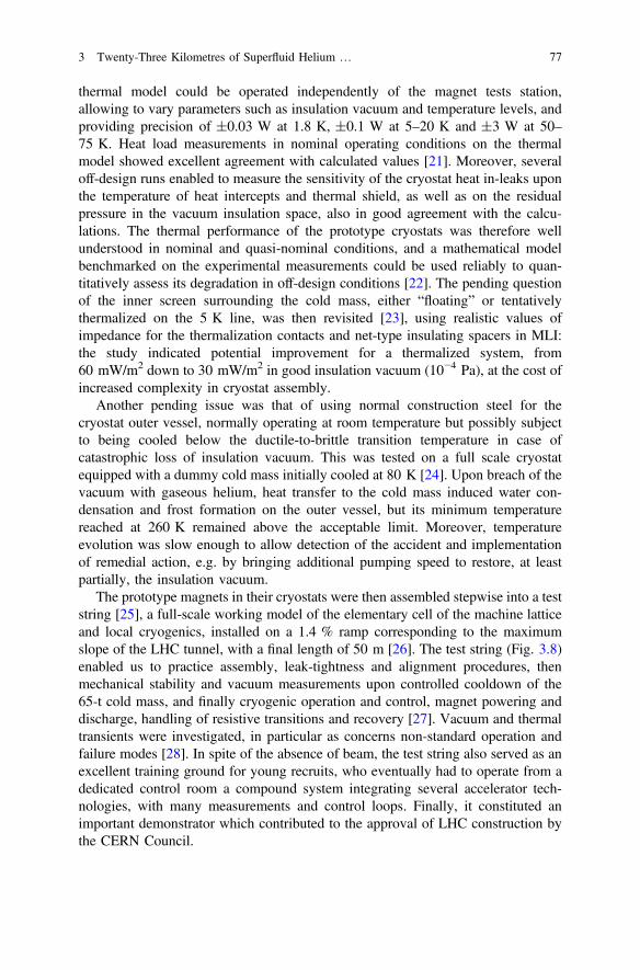
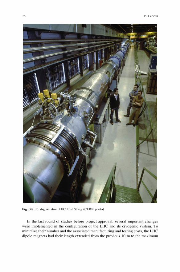
The prototype magnets in their cryostats were then assembled stepwise into a teststring [25], a full-scale working model of the elementary cell of the machine latticeand local cryogenics, installed on a 1.4 % ramp corresponding to the maximumslope of the LHC tunnel, with a final length of 50 m [26]. The test string (Fig. 3.8)enabled us to practice assembly, leak-tightness and alignment procedures, thenmechanical stability and vacuum measurements upon controlled cooldown of the65-t cold mass, and finally cryogenic operation and control, magnet powering anddischarge, handling of resistive transitions and recovery [27]. Vacuum and thermaltransients were investigated, in particular as concerns non-standard operation andfailure modes [28]. In spite of the absence of beam, the test string also served as anexcellent training ground for young recruits, who eventually had to operate from adedicated control room a compound system integrating several accelerator tech-nologies, with many measurements and control loops. Finally, it constituted animportant demonstrator which contributed to the approval of LHC construction bythe CERN Council.
3 Twenty-Three Kilometres of Superfluid Helium … 77
In the last round of studies before project approval, several important changeswere implemented in the configuration of the LHC and its cryogenic system. Tominimize their number and the associated manufacturing and testing costs, the LHCdipole magnets had their length extended from the previous 10 m to the maximum
Fig. 3.8 First-generation LHC Test String (CERN photo)
78 P. Lebrun
which could be practically transported in European roads (40-t limit) and conve-niently handled for assembly, testing and installation, i.e. 15 m, thus requiring new,longer cryostats. In order not to lose in useful aperture, the cold mass had to becurved, with a horizontal sagitta of 9 mm, but the cryostats could remain straight.As concerns cryogenic system architecture, grouping all refrigeration equipment inthe five points around the ring (instead of eight) already equipped with technicalinfrastructure led to significant cost savings, and allowed for redundancy atpart-load, but cryogenic flows had then to be distributed over the full 3.3 km lengthof the sectors (instead of half-sectors). This required larger-diameter pipes whichbecame difficult to integrate in the cryostat transverse cross-section. Consequently,all distribution pipework and local equipment was moved to a compound cryogenicline running in the tunnel along the magnets, and the remaining pipework in thecryostats was then limited to that needed for operation of the cryostat proper.Another important consequence is that the cryogenic line could be installed,commissioned and tested independently of the progress in magnet installation, thusbringing valuable schedule flexibility in the last phase of project construction [29].Moreover, it had been observed that in view of the large size of the LHC ring,“passive” cryogenics, i.e. magnet cryostats and cryogenic distribution representedthe largest share of the cost breakdown, in fact larger than “active” cryogenics, i.e.the refrigeration plants. Consequently, any simplification of the cryostats andcryogenic distribution scheme, even though it may result in increasing the refrig-eration duty, would concur to lowering the total cost. A simplified cryogenicscheme was then implemented [30], with local cooling loops extending over thelength of a full lattice cell (106.9 m) instead of the previous half-cell, implemen-tation of local 4.5–2.2 K sub-cooling heat exchangers in each local cooling loopallowing the suppression of one pipe inside the distribution line, and a large overallreduction in the number of cryogenic components.
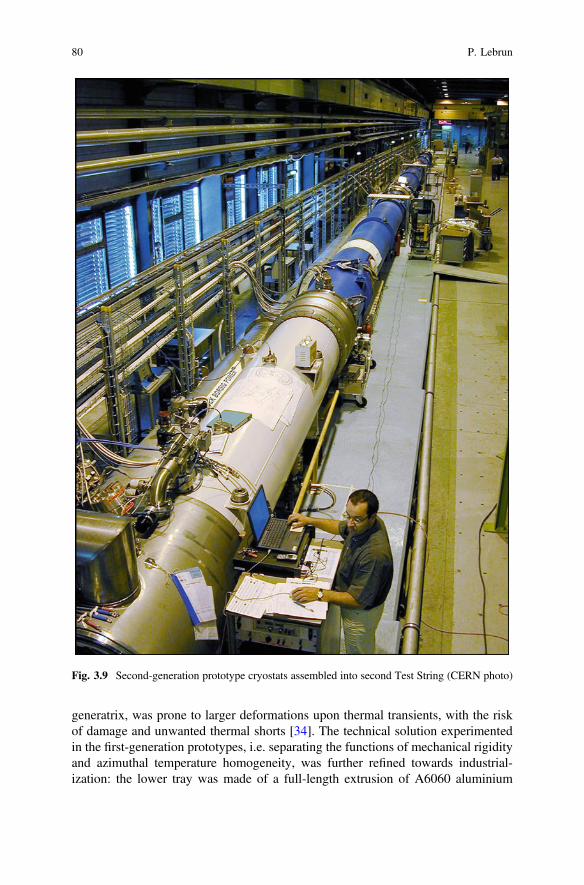
A second generation of prototype cryostats for dipoles [31] andshort-straight-sections [32] was then designed and built, based on the experienceacquired with the first-generation prototypes and incorporating the changes in LHCconfiguration described above. In the dipole cryostat (Fig. 3.9) the smaller outerdiameter (914 mm) allowed the shell of the vacuum vessel to be made of standard,helically welded elements for pipelines, with a wall thickness of 12 mm. To preventany risk of embrittlement, the construction steel used (DIN GS-21 Mn5) washowever specified to have a minimum energy absorption of 28 J/cm2 as measuredin an ISO-standard Charpy test at 240 K. The shells were equipped with AISI 304Lend flanges and reinforced, at the longitudinal positions of the magnet supports, bywelded rings and forged brackets for lifting points and alignment fiducials. Thelonger, heavier cold mass was still supported on three posts, the longitudinalpositions of which were compromised between minimizing vertical sagitta (Besselconditions) and keeping the ends of the cold mass horizontal to ease interconnectassembly (Airy conditions). The vertical off-axis between magnet and cryostat axeswas reduced to 80 mm, thus requiring shorter support post of 210 mm total height,redesigned to take higher combined loading of 125 kN in axial compression and40 kN in shear [33]. The longer thermal shield, a quasi-cylinder cooled from one
3 Twenty-Three Kilometres of Superfluid Helium … 79
generatrix, was prone to larger deformations upon thermal transients, with the riskof damage and unwanted thermal shorts [34]. The technical solution experimentedin the first-generation prototypes, i.e. separating the functions of mechanical rigidityand azimuthal temperature homogeneity, was further refined towards industrial-ization: the lower tray was made of a full-length extrusion of A6060 aluminium
Fig. 3.9 Second-generation prototype cryostats assembled into second Test String (CERN photo)
80 P. Lebrun
alloy, integrating two 80 mm diameter channels, one used for the cooling, the otherleft open (Fig. 3.10). The cooling channel was fitted at the ends withaluminium-to-stainless steel pipe transitions for interconnection. The upper shell ofthe thermal shield made of commercially pure aluminium A1100, was segmented infive sections (Fig. 3.11). A semi-rigid screen, thermalized to the 5 K pipes pro-viding heat intercepts on the support posts was tentatively re-introduced in thesecryostats with the aim of further reducing the heat in-leak on the cold mass. Thecryostat interconnect was also redesigned to accommodate installation misalign-ments of up to ±4 mm in any direction and thermal contractions of up to 48 mmbetween the longitudinally fixed central posts of neighbouring dipoles. Theshort-straight section cryostat (Fig. 3.12), designed in collaboration with IPN Orsay(France) incorporated many design features of the dipole cryostat, and showed asimilar transverse cross-section. It was equipped with a vacuum barrier for seg-menting the insulation vacuum, and a cryogenic service module connected to thecryogenic distribution line by a multi-pipe “jumper” connection. The servicemodule also contained beam position monitors, conduction-cooled current leads forthe independently-powered orbit corrector magnets, and instrumentation feed-throughs. However, all local cryogenic equipment was now moved to the cryogenicline on the other side of the jumper connection.
Fig. 3.12 Longitudinal cross-section of the second-generation short-straight-section cryostat
82 P. Lebrun
Five second-generation dipole cryostats, and two short-straight section cryostatswere procured from industry and assembled around their magnets for cold testingand installation into a 107 m long second-generation test string [35], the lastlarge-scale experimental validation of the LHC accelerator systems before enteringconstruction. A first systematic risk analysis of the LHC cryogenic system [36]established all possible failure modes and analysed their consequences, thus con-firming the cryostat design parameters and safety features.
3.4 Industrial Series Production, Installationand Commissioning
The design of the series cryostats (Fig. 3.13) derived directly from thesecond-generation prototypes, the measured thermal performance of which wasused to establish reliably a reference thermal budget for the purpose of sizing thecryogenic refrigeration plants and distribution system. A “heat-load working group”involving all stakeholders was established to collect all calculated and measureddata, validate the estimates (Table 3.1) and track possible future evolutions.
Changes of a few manufacturing aspects streamlined the design towardsindustrialization in view of series production [37]. Trading moderate improvement
Fig. 3.13 Transverse cross-section of series dipole cryostat
3 Twenty-Three Kilometres of Superfluid Helium … 83
of thermal performance against complexity and cost, the 5 K thermalization of thescreen was finally not retained, and the cold mass was eventually covered with a10-layer blanket of MLI. The complete rationale for this choice is summarized inRef. [38]. Following completion of welding work, the series vacuum vessels werestress-relieved by vibration to ensure mechanical stability over time. Instead of thepreviously used low-outgassing epoxy paint, their inner surface was sandblastedand simply cleaned to high-vacuum standards, with no other surface treatment.Magnet support posts (Fig. 3.14) were composed of monolithic 4 mm thick
Table 3.1 Heat in-leaks of 106.9 m long standard cell (6 dipoles and 2 short straight sections)
50–75 K 4.5–20 K 1.9 K
Magnet support posts (W) 157 9.78 1.07
Thermal shield (W) 301 – –
Cold mass MLI (W) – 0.85 11.3
Beam screen (W) – – 1.62
Instrumentation feedthrough (W) – – 4.25
Beam vacuum feedthrough (W) 2.40 – 0.42
Orbit corrector current leads (W) 10.4 2.44 0.53
Beam position monitor (W) – 0.93 0.60
Cryogenic service module (W) – 0.01 0.21
Vacuum barrier (W) 11.6 0.03 0.42
Total heat in-leak (W) 482 14.0 20.4Average linear heat in-leak (W/m) 4.51 0.13 0.19
Fig. 3.14 Glassfibre-reinforced epoxy support post (CERN photo)
84 P. Lebrun
columns of glass-fibre reinforced epoxy, manufactured by resin-transfer moulding,a highly automated technique ensuring low production cost and reproduciblequality for series of 4700 units [39]. At the heat intercept locations, external flangesof aluminium alloy and internal stainless-steel reinforcement rings are glued to thecolumns. Aluminium anti-radiation disks and reflective coating on the lower,warmer section exposed to radiation from the room-temperature outer vessel,complete the assembly. The 30-layer MLI around the thermal shield and 10-layerMLI around the cold mass were made of pre-fabricated blankets of 6 mm thick PETfilm, double-aluminized with 400 Å, interleaved by a very low weight polyesterspacer. The developed perimeter of each blanket was adjusted to compensate fortheir differential thermal contraction with the stainless-steel and aluminium shellssupporting them. Besides more precise manufacturing, pre-fabrication enabled themultilayer insulation systems to be assembled by non-specialized personnel, usingVelcro™ fasteners, and avoided installation errors, thus ensuring future thermalperformance of the multilayer insulation systems in the LHC ring.
For series production, it was decided to get the cryostats assembled by industryon the CERN premises, with CERN procuring all components and providing thecontractors with a build-to-print specification, the use of two assembly hallstotalling some 10,000 m2 floor space, lifting and transport facilities, heavy andspecialized tooling, detailed procedures and quality management tools, as well aswith initial training of the execution personnel on the pre-series units, co-assembledwith CERN experts (Figs. 3.15 and 3.16). Assembly of the 1232 dipole and 474short-straight-section cryostats spanned five years, representing some 850,000 h ofwork with personnel numbers—operators and technicians—peaking at 145 [40].
Fig. 3.15 Dipole cryostat assembly hall (CERN photo)
3 Twenty-Three Kilometres of Superfluid Helium … 85
Following assembly, each cryo-magnet was moved to the test hall using aspecially designed vehicle used for both lifting and transport (Fig. 3.17), connectedto one of the twelve test benches, pumped down, cooled down and cryogenicallytested, with the magnet powered up to 10 % above nominal (Fig. 3.18). Magneticmeasurements in cold conditions were only performed on a fraction of the pro-duction. After removal from the test bench each cryo-magnet was allocated aposition in the ring based on test results, prepared for installation and lowered to thetunnel level via a large, elliptical shaft equipped with a 40-t gantry crane with ahook travel of 54 m. The major axis of 18 m of the elliptical shaft is able toaccommodate the full assembled length of a cryo-dipole, with protection endcovers, horizontally (Fig. 3.19).
Cryostat assembly and cryogenic tests followed the production rate of magnetsin industry (Fig. 3.20), while installation in the tunnel started later and proceeded ata faster rate. As a consequence, a large buffer storage of assembled and testedcryo-magnets was available, enabling the optimization of their final installationpositions in the accelerator tunnel in order to reduce dispersion in the magnetic andgeometrical properties of assembled sectors. The cryo-magnets were stored in theopen air for several months, with their ends capped and insulation space kept underdry nitrogen.
Fig. 3.16 Short-straight-section cryostat assembly hall (CERN photo)
86 P. Lebrun
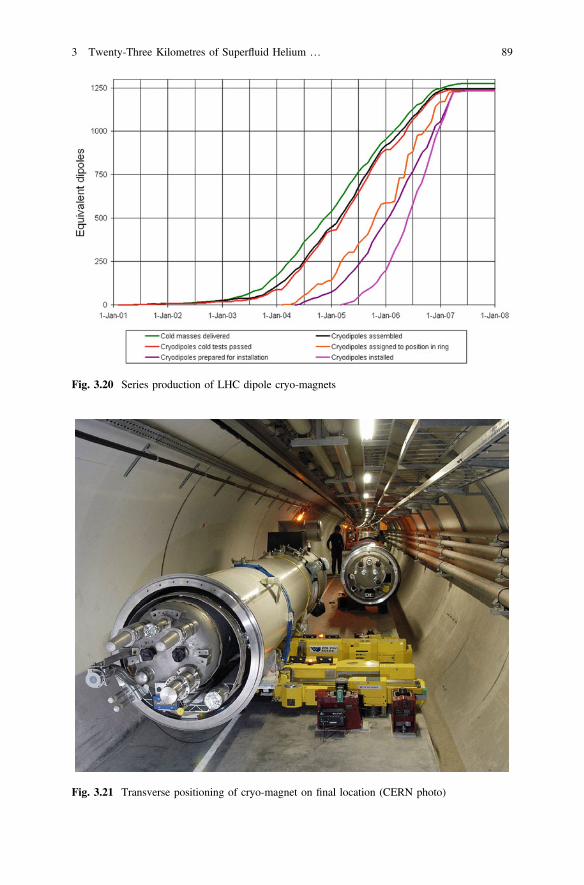
Transport in the tunnel from the shaft to the installation position was done via anoptically guided, electrically powered trolley at low velocity (3 km/h) to minimizeinertial forces in view of the large masses transported. On location, the cryo-magnetweight was loaded to a transverse transfer platform, and then transferred onto itspre-positioned final support jacks (Fig. 3.21). Electrical magnet interconnectionsand hydraulic cryostat interconnections were then performed. This was done by
Fig. 3.17 Completed dipole cryo-magnet transported to test hall (CERN photo)
Fig. 3.18 Cryogenic tests of magnets at CERN (CERN photo)
3 Twenty-Three Kilometres of Superfluid Helium … 87
industry in the framework of a build-to-print contract. CERN developed themethods, special tooling and quality assurance procedures to be used by the con-tractor, and provided initial training of its personnel [41]. Some 40,000 cryogenicpipe welds were reliably executed using automatic TIG orbital welders (Fig. 3.22).The inner part of a completed cryo-magnet interconnection, with the MLI blankets,thermal shield and outer vacuum sleeve removed, is shown in Fig. 3.23. The domedends of the helium vessels, as well as the reflective multilayer insulation blanketscovering the cold mass and the thermal shield, are clearly visible on either side ofthe interconnection.
Following global pressure and leak-tightness tests, each 3.3 km sector of theLHC was cooled down and powered. Total sector heat in-leaks (Fig. 3.24) weremeasured within the estimated values [42], a final validation of the quality of thedesign, construction and installation of the cryostats.
Fig. 3.19 Lowering ofcryo-magnet to LHC tunnelvia elliptical shaft (CERNphoto)
88 P. Lebrun
Fig. 3.20 Series production of LHC dipole cryo-magnets
Fig. 3.21 Transverse positioning of cryo-magnet on final location (CERN photo)
3 Twenty-Three Kilometres of Superfluid Helium … 89
Fig. 3.22 Cryogenic piping interconnection in LHC tunnel by orbital TIG welding (CERN photo)
The LHC contains the largest system of advanced, high-performance cryostatshousing superconducting accelerator devices, and may thus be considered, mutatismutandis, as reference for future, similar projects. Several lessons can be drawnfrom this experience.
The technology of superfluid helium can be reliably applied to very large sys-tems built by industry. In particular, the design principles, construction techniquesand quality assurance methods used in normal helium cryostats are fully adequate toensure leak-tightness of superfluid helium enclosures.
Cryostats of superconducting accelerator devices, magnets or RF cavities, mustmeet complex and often conflicting geometrical, mechanical and thermal require-ments, at the interface between accelerator physics and technology requirements,industrial manufacturing constraints and cost. Their design must therefore followclosely the changes in configuration of the project and sometimes drive them. It istherefore essential for the cryostat designers to be fully integrated with the projectteam and in close contact with the magnet, RF, cryogenics and vacuum groups.
Within the cryogenic system, the total cost of the cryostats and distribution linesoften exceeds that of the refrigeration plants. Global optimization of the completesystem is therefore necessary, which may lead to simplify cryostat construction atthe cost of loss in thermal performance, rather than designing for lowest possibleheat-in-leak.
The large amount of thorough design and development work performed at CERNand in partner laboratories on the LHC cryostats has contributed to significantlyincrease knowledge and confidence in the design, engineering and quality assurancemethods for this type of equipment. It is interesting to note that this work has alreadyfound an application in another project. Cryostats similar to those of the LHC dipolesare housing the superconducting magnets of the beam line for the T2K long-baselineneutrino experiment at the J-PARC laboratory in Tokai, Japan [43]. On the trainingand education side, a tutorial on cryostat design inspired from the development ofLHC cryostats was first prepared for the CERN Accelerator School
On average, measured values 20 % lower than design estimates
Fig. 3.24 Measured heat in-leaks of LHC sectors at 1.9 K (DR design report estimates; IT innerquadrupole triplet)
3 Twenty-Three Kilometres of Superfluid Helium … 91
“Superconductivity and Cryogenics for Accelerators and Detectors” in 2002 [44]and is now part of the curriculum of the yearly European Course of Cryogenicscommonly organized by the Technical University of Dresden, the WroclawUniversity of Technology and the Norwegian University of Science and TechnologyTrondheim. This has been further developed as a course in a more recent venue ofthe CERN Accelerator School on “Superconductivity for Accelerators” [45].
Acknowledgments Having been involved in this work from the onset, the author has tried toconvey his strong conviction that the success of LHC cryostats is the result of teamwork by manycontributors at CERN, in partner laboratories and in industry. A number of them appear asco-authors in the reference list below. The expertise, dedication and hard work of all should beacknowledged.
References
1. LHC Design Report, vol. I, The LHC Main Ring, CERN-2004-003 (2004). ISBN92-9083-224-0
2. P. Lebrun et al., Cooling strings of superconducting devices below 2 K: the helium II bayonetheat exchanger. Adv. Cryo. Eng. 43A, 419–426 (1998)
3. P. Lebrun, Cryogenics for the Large Hadron Collider. IEEE Trans. Appl. Supercond. 10,1500–1506 (2000)
4. A. Asner et al., A feasibility study of possible machine options, in Proceedings ofECFA-CERN Workshop on Large Hadron Collider in the LEP Tunnel, Lausanne,CERN-84-10-V-1 (1984), pp. 49–142
5. G. Claudet, R. Aymar, Tore Supra and helium II cooling of large high-field magnets. Adv.Cryo. Eng. 35A, 55–67 (1990)
6. G. Claudet et al., Preliminary study of a superfluid helium cryogenic system for the LargeHadron Collider, in Proceedings of Workshop on Superconducting Magnets and Cryogenics,Brookhaven BNL 52006 (1986), pp. 270–275
7. V. Baglin et al., Cryogenic beam screens for high-energy particle accelerators, in Proceedingsof ICEC24-ICMC 2012 Fukuoka, Cryogenics and Superconductivity Society of Japan (2013),pp. 629–634
8. G. Claudet et al., Conceptual study of the superfluid helium cryogenic system for the CERNLarge Hadron Collider, in Proceedings of ICEC12 Southampton, Butterworth (1988),pp. 497–504
9. T. Nicol, SSC Collider Dipole Cryostat, Chap. 2, this book10. H. Danielsson et al., Precision heat inleak measurements on cryogenic components at 80 K,
4.2 K and 1.8 K. Cryogenics 32(ICEC Supplement), 215–218 (1992)11. P. Lebrun et al., Investigation and qualification of thermal insulation systems between 80 K
and 4.2 K. Cryogenics 32(ICMC Supplement), 44–47 (1992)12. M. Granier et al., Design and construction of a superfluid-helium cryostat for a ten-meter long
13. M. Granier et al., Performance of the twin-aperture dipole for the CERN LHC, in Proceedingsof EPAC’92, JACoW (1992), pp. 1414–1416
14. P. Lebrun et al., Investigation of quench pressure transients in the LHC superconductingmagnets. Cryogenics 34(ICEC Supplement), 705–708 (1994)
15. J.-C. Brunet et al., Design of LHC prototype dipole cryostats. Cryogenics 32(ICECSupplement), 191–194 (1992)
92 P. Lebrun
16. M. Blin et al., Design, construction and performance of superconducting magnet support postsfor the Large Hadron Collider. Adv. Cryo. Eng. 39A, 671–678 (1994)
17. W. Cameron et al., Design and construction of a prototype superfluid helium cryostat for theShort Straight Sections of the CERN Large Hadron Collider. Adv. Cryo. Eng. 39, 657–662(1994)
18. V. Benda et al., Cryogenic infrastructure for superfluid helium testing of LHC prototypesuperconducting magnets. Adv. Cryo. Eng. 39, 641–648 (1994)
19. V. Benda et al., Cryogenic benches for superfluid helium testing of full-scale prototypesuperconducting magnets for the CERN LHC project. Cryogenics 34(ICEC Supplement),733–736 (1994)
20. L. Dufay et al., A full-scale thermal model of a prototype dipole cryomagnet for theCERN LHC project. Cryogenics 34(ICEC Supplement), 693–696 (1994)
21. V. Benda et al., Measurement and analysis of thermal performance of LHC prototypecryostats. Adv. Cryo. Eng. 41, 785–792 (1996)
22. G. Riddone, Theoretical Modelling and Experimental Investigation of the ThermalPerformance of LHC Lattice Cryostats. Doctoral Thesis, Politecnico di Torino (1996)
23. G. Ferlin et al., Comparison of floating and thermalized multilayer insulation systems at lowboundary temperature, in Proceedings of ICEC16-ICMC 1996, North-Holland (1997),pp. 443–446
24. P. Lebrun et al., Experimental investigation of accidental loss of insulation vacuum in a LHCprototype dipole cryostat. Adv. Cryo. Eng. 41, 799–804 (1996)
25. A. Bézaguet et al., The superfluid helium cryogenic system for the LHC test string: design,construction and first operation. Adv. Cryo. Eng. 41, 777–784 (1996)
26. A. Bézaguet et al., Cryogenic operation and testing of the extended LHC prototype magnetstring, in Proceedings of ICEC16-ICMC 1996, North-Holland (1997), pp. 91–94
27. M. Chorowski et al., Thermohydraulics of quenches and helium recovery in the LHCprototype magnet strings. Cryogenics 38, 533–543 (1998)
28. P. Cruikshank et al., Investigation of thermal and vacuum transients on the LHC prototypemagnet string, in Proceedings of ICEC16-ICMC 1996, North-Holland (1997), pp. 681–684
29. V. Benda et al., Conceptual design of the cryogenic system for the Large Hadron Collider, inProceedings of EPAC’96 Sitges, JACoW (1996), pp. 361–363
30. M. Chorowski et al., A simplified cryogenic distribution scheme for the Large HadronCollider. Adv. Cryo. Eng. 43A, 395–402 (1998)
31. J.-C. Brunet et al., Design of the second-series 15 m LHC prototype dipole magnet cryostats.Adv. Cryo. Eng. 43A, 435–441 (1998)
32. W. Cameron et al., The new superfluid helium cryostats for the Short Straight Sections of theCERN Large Hadron Collider. Adv. Cryo. Eng. 43A, 411–418 (1998)
33. M. Mathieu et al., Supporting systems from 293 K to 1.9 K for the Large Hadron Collider.Adv. Cryo. Eng. 43A, 427–434 (1998)
34. G. Peon, G. Riddone, L.R. Williams, Analytical model to calculate the transientthermo-mechanical behaviour of long thin structures cooled from a pipe: application to theLHC dipole thermal shield, in Proceedings of ICEC16-ICMC 1996, North-Holland (1997),pp. 477–480
35. E. Blanco et al., Experimental validation and operation of the LHC Test String 2 cryogenicsystem. Adv. Cryo. Eng. 49, AIP Conf. Proc. 710, 233–240 (2004)
36. M. Chorowski, P. Lebrun, G. Riddone, Preliminary risk analysis of the LHC cryogenicsystem. Adv. Cryo. Eng. 45B, 1309–1316 (2000)
37. N. Bourcey et al., Final design and experimental validation of the thermal performance of theLHC lattice cryostats. Adv. Cryo. Eng. 49, AIP Conf. Proc. 710, 487–493 (2004)
38. P. Lebrun, V. Parma, L. Tavian, Does one need a 4.5 K screen in cryostats of superconductingaccelerator devices operating in superfluid helium? Lessons from the LHC. Adv. Cryo. Eng.59A, AIP Conf. Proc. 1573, 245–252 (2014)
3 Twenty-Three Kilometres of Superfluid Helium … 93
39. V. Parma et al., The LHC cryomagnet supports in glass-fibre reinforced epoxy: a large-scaleindustrial production with high reproducibility in performance. Adv. Cryo. Eng. 54, AIP Conf.Proc. 986, 211–218 (2008)
40. A. Poncet, V. Parma, Series-produced helium II cryostats for the LHC magnets: technicalchoices, industrialization, costs. Adv. Cryo. Eng. 53A, AIP Conf. Proc. 985, 739–746 (2008)
41. J-Ph Tock et al., The interconnections of the LHC cryomagnets at CERN: strategy applied andfirst results of the industrialization process. IEEE Trans. Appl. Supercond. 18(2), 116–120(2008)
42. S. Claudet at al., Cryogenic heat load and refrigeration capacity management at the LargeHadron Collider, in Proceedings of ICEC22—ICMC 2008, KIASC (2009), pp. 835–840
43. T. Nakamoto et al., Construction of superconducting magnet system for the J-PARC neutrinobeam line. IEEE Trans. Appl. Supercond. 20(3), 208–213 (2010)
44. P. Lebrun, Design of a cryostat for superconducting accelerator magnets: the LHC maindipole case, in Proceedings of CAS Superconductivity and Cryogenics for Accelerator andDetectors, CERN-2004-008, ISBN 92-9083-230-4 (2004), pp. 348–362
45. V. Parma, Cryostat design, in Proceedings of CAS Superconductivity for Accelerators,CERN-2014-005 (2014), pp. 353–399. ISBN 978-92-9083-405-2