Devers-Palo Verde No. 2 Chapter 3 – Description of Proponent’s Environmental Assessment the Proposed Project 3-1 CHAPTER 3.0 DESCRIPTION OF THE PROPOSED PROJECT 3.1 PROJECT DEVELOPMENT PROCESS 3.1.1 Overview This section describes the steps taken by SCE and the status of permitting actions previously taken by state and federal regulatory agencies in the development of the DPV2 transmission line project. Additional permits or actions required prior to construction of the proposed DPV2 project are listed in Section 3.1.4. The proposed route for the Devers-Harquahala 500kV transmission line is located generally parallel to SCE’s existing DPV1 500kV transmission line route (see Chapter 1, Map 1-1; and Maps 3-2a-c, end of Chapter 3). Electrical systems and siting studies were conducted prior to construction of the DPV1 line. A regional siting study was conducted by SCE in 1976-1977 to identify alternative routes between Devers Substation and PVNGS within a 6,000-square-mile area. Subalternate routes were evaluated in the DPV1 Draft Environmental Impact Statement (DEIS) prepared by the USDOI-BLM and NRC (BLM and NRC, July 1978). These agencies selected the preferred route for the DPV1 transmission line that was constructed in 1982 following state approvals by the CPUC and the Arizona Corporation Commission (ACC). After construction of the DPV1 line, applications to construct the DPV2 500kV transmission line using the proposed route between Devers Substation and PVNGS were submitted by SCE in 1985. The CPCN application and PEA included the proposed route and four subalternates from the DPV1 studies that were completed in 1978. Agency approvals and other actions pertaining to the DPV2 project are described as follows, and listed in Table 3-1.
Transcript
Devers-Palo Verde No. 2 Chapter 3 – Description of Proponent’s Environmental Assessment the Proposed Project
3-1
CHAPTER 3.0 DESCRIPTION OF THE PROPOSED PROJECT
3.1 PROJECT DEVELOPMENT PROCESS
3.1.1 Overview
This section describes the steps taken by SCE and the status of permitting actions previously
taken by state and federal regulatory agencies in the development of the DPV2 transmission line
project. Additional permits or actions required prior to construction of the proposed DPV2
project are listed in Section 3.1.4.
The proposed route for the Devers-Harquahala 500kV transmission line is located generally
parallel to SCE’s existing DPV1 500kV transmission line route (see Chapter 1, Map 1-1; and
Maps 3-2a-c, end of Chapter 3). Electrical systems and siting studies were conducted prior to
construction of the DPV1 line. A regional siting study was conducted by SCE in 1976-1977 to
identify alternative routes between Devers Substation and PVNGS within a 6,000-square-mile
area. Subalternate routes were evaluated in the DPV1 Draft Environmental Impact Statement
(DEIS) prepared by the USDOI-BLM and NRC (BLM and NRC, July 1978). These agencies
selected the preferred route for the DPV1 transmission line that was constructed in 1982
following state approvals by the CPUC and the Arizona Corporation Commission (ACC).
After construction of the DPV1 line, applications to construct the DPV2 500kV transmission line
using the proposed route between Devers Substation and PVNGS were submitted by SCE in
1985. The CPCN application and PEA included the proposed route and four subalternates from
the DPV1 studies that were completed in 1978. Agency approvals and other actions pertaining to
the DPV2 project are described as follows, and listed in Table 3-1.
Devers-Palo Verde No. 2 Chapter 3 – Description of Proponent’s Environmental Assessment the Proposed Project
3-2
TABLE 3-1 DPV2 AGENCY APPROVALS AND OTHER ACTIONS
Document Date Agency Action
CPCN Application including PEA 12/85 CPUC Initial filing
Draft Environmental Impact Report 03/87 CPUC State of California public and agency review
Supplemental Draft Environmental Impact Statement
05/87 USDOI/BLM Review in compliance with NEPA
Final EIR 08/05/87 CPUC Compliance with California Environmental Quality Act
Arizona Certificate of Environmental Compatibility Application filed (Case No. 76)
11/16/87 ACC Filed application for state of Arizona review (withdrawn)
08/88 CPUC Incorporated SCE/Division of Ratepayer Advocates cost/benefit study
Addendum to FEIR 09/88 CPUC Review required for amended PEA
Final SEIS 10/88 USDOI/BLM Proposed project and route adjacent to DPV1 approved
Interim Opinion (Decision No. 88-12-030) 12/09/88 CPUC Interim Order Granting conditional approval for CPCN and route
Record of Decision 02/21/89 BLM Approved project and preferred route in compliance with NEPA
Certificate of Right-of-Way Compatibility 03/01/89 USFWS Certified compatibility of 500kV transmission line on KOFA NWR land
Right-of-Way Grant (CA-17905/AZ-23805)
08/11/89 BLM Right-of-way permitted across federal land
SCE Ten-Year Plan filed 02/28/94 ACC Notice of SCE’s plan to construct in Arizona
SCE applied to the CPUC for a CPCN for DPV2 in 1985. Following reviews of SCE’s PEA
(1985) and the CPUC EIR (1987) and subsequent filing and review of SCE’s 1988 Amended
Application and PEA (SCE 1988), the CPUC issued a decision approving the then proposed
route for DPV2. The Interim Order issued in December 1988 granted a CPCN to SCE that
allowed construction of the project, conditioned upon compliance with an environmental
mitigation program and other conditions as specified in the CPUC Final EIR (1987).
The USDOI – BLM approved the DPV2 project and the proposed route following completion of
a FSEIS (BLM 1988) in compliance with NEPA, and issued a ROD in 1989. Later that year, the
BLM issued a Right-of-Way Grant to SCE for the construction, operation, and maintenance of
DPV2 across federal land, pursuant to Title V of the Federal Land Policy and Management Act
Devers-Palo Verde No. 2 Chapter 3 – Description of Proponent’s Environmental Assessment the Proposed Project
3-3
of 1976. In 1989, USFWS issued a CRC for the portion of the DPV2 route that crosses the
KOFA NWR in Arizona.
The route that was proposed in the 1985 Application and PEA, and 1988 Amended Application
and PEA, followed the existing DPV1 line and terminated at PVNGS. The termination point of
the 500kV transmission line route that is proposed in the current application is the Harquahala
Generating Station Switchyard, located approximately 16 miles directly northwest of PVNGS
(see Map 1-1). The distance of the proposed route between Devers Substation and the
Harquahala Generating Station is approximately 230 miles and follows the existing DPV1 line
for a distance of 225 miles, approximately 8 miles shorter than the route proposed in the previous
DPV2 applications.
The majority of the proposed Devers-Harquahala 500kV transmission line would be constructed
within the 130-foot-wide right-of-way on public land granted in perpetuity to SCE for the DPV2
project by the BLM in 1989. The right-of-way was granted for a total of 149.9 linear miles of
public land between Devers and PVNGS, 57.2 miles in California and 92.7 miles in Arizona,
including land managed by the BLM, USFWS, U.S. Department of Defense (DOD), and U.S.
Bureau of Reclamation (USBR). The proposed Devers-Harquahala 500kV transmission line
route would require a total of 136.6 miles of public land, as shown in Table 3-2. The Devers-
Harquahala 500kV route also is within utility corridors as designated in the BLM RMPs for each
of the respective BLM planning areas in Arizona and California. Construction would proceed as
authorized by the BLM, incorporating the mitigation measures identified in the final versions of
the FEIR, FSEIS, ROD, Right-of-Way Grant, CEC, and CRC.
Devers-Palo Verde No. 2 Chapter 3 – Description of Proponent’s Environmental Assessment the Proposed Project
3-4
TABLE 3-2 DPV2 RIGHT-OF-WAY GRANT AND PROPOSED DEVERS-HARQUAHALA
500kV TRANSMISSION LINE RIGHT-OF-WAY Land Management Agency Total Miles of Right-of-Way
DPV2 Right-of-Way Grant (BLM 1989)
Proposed Devers-Harquahala
500kV Transmission Line
BLM 123.8 110.5
USFWS 26.1 26.1
Total 149.9 136.6 Note: BLM land withdrawals include DOD, Yuma Proving Ground (0.1 mile); USBR, CAP Canal (0.1.mile). USFWS land includes the KOFA NWR (23.8 miles) and Coachella Valley NWR (2.3 miles).
Additional right-of-way requirements include Arizona State Trust Land (10.8 miles), California
State Land (0.6 mile), Agua Caliente Indian Reservation (0.1 mile), and private land (81.6
miles). Some portions of the right-of-way were previously acquired from private owners by SCE.
The Devers-Harquahala 500kV right-of-way acquired on private land, adjacent to the DPV1
right-of-way, will be a minimum of 130 feet wide.
Reinforcement of the 230kV system west of Devers was planned for the proposed 1985 DPV2
project. The proposed DPV2 project, for which SCE is now requesting CPUC approval, also
includes upgrades to SCE’s 230kV system west of Devers. The proposed improvements would
be constructed within SCE’s existing right-of-way that consists of one set of double-circuit
towers and two separate sets of single-circuit structures between Devers and San Bernardino
Junction (40 miles). San Bernardino Junction is the intersection of 230kV transmission line
corridors located 3.4 miles south of the San Bernardino Substation. The proposed 230kV system
upgrade west of Devers would require the removal of an existing single-circuit 230kV
transmission line on wood H-frame structures, and the removal of an existing single-circuit
230kV transmission line on lattice steel structures between Devers and San Bernardino Junction;
replacement with a new double-circuit 230kV line; and reconductoring and modification of the
existing double-circuit 230kV line. Also, the upgrade would require reconductoring both circuits
on an existing double-circuit 230kV tower line between Vista Substation and San Bernardino
Junction. In addition, one circuit on each of the two existing double-circuit 230kV tower lines
Devers-Palo Verde No. 2 Chapter 3 – Description of Proponent’s Environmental Assessment the Proposed Project
3-5
between the San Bernardino Junction and San Bernardino Substation (3.4 miles) would be
reconductored.
The upgrade will result in four 230kV circuits, each with new 1033.5 thousand circular mil
In addition to the routing alternatives for the proposed 500kV line, the Midpoint Substation is
considered as an alternative component that could be constructed in conjunction with the
proposed DPV2 Project. This PEA includes the evaluation of one preferred site and two
alternative sites for the substation that would be located south and west of Blythe, California, as
shown on Maps 3-2a and 3-2b. Descriptions of the Midpoint Substation preferred site and
alternative sites also are provided in Section 3.2.2.4.
The proponents of the California DSWTP are proposing to construct a 500kV transmission line
from Blythe to Devers adjacent to the proposed Devers-Harquahala 500kV transmission line.
Under a joint project proposal, only one instead of two 500kV transmission lines would be
constructed since the parties would share a single 500kV transmission line. The joint project
would include the construction of a 500kV substation. Initially, the Midpoint Substation would
be equipped only with switching facilities to provide interconnections for the DPV1, Devers-
Harquahala, and DSWTP 500kV lines. In the future, 500/230/161/66kV substation equipment
would be installed. The Midpoint Substation would be completed in March 2009.
The preferred location for the Midpoint Substation, as shown in Map 3-2a, is about 10 miles
southwest of Blythe, California, adjacent to SCE’s DPV1 right-of-way. The preferred site is
located on BLM land immediately west of IID’s Blythe-Niland 161kV transmission line and
Western’s Blythe-Knob 161kV transmission line. A preliminary block diagram for the Midpoint
Devers-Palo Verde No. 2 Chapter 3 – Description of Proponent’s Environmental Assessment the Proposed Project
3-16
Substation is presented in Figure 3-1. The Midpoint Substation would be constructed within a
rectangular area approximately 1,000 feet by 1,900 feet, or 44 acres. The switching facilities
would be constructed within the Midpoint Substation property.
The 500kV switching station would include buses, circuit breakers, and disconnect switches. The
switchyard would be equipped with 108-foot-high dead-end structures.
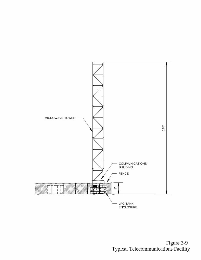
A new telecommunications facility would be installed on site to provide microwave and fiber
optic communications for protective relaying and special protection scheme requirements. Three
new microwave paths and two fiber optic systems would be installed at the Midpoint Substation
site. The proposed fiber optic systems are Midpoint-Buck Boulevard Substation and Midpoint-
Devers-Harquahala. The telecommunications facilities are described in Section 3.4.2.4.
A 45-foot by 70-foot mechanical-electrical equipment room would be installed on site to house
all controls and protective equipment and a telecommunications room. A microwave tower also
would be installed at the substation site.
A review of several potential siting areas for the Midpoint Substation was conducted by SCE in
February 2004. The review considered engineering, environmental, and land availability criteria.
Based on this review, a preferred site and two alternative sites were identified that would be
feasible for construction and operation of the substation. These sites are described in Section
3.2.2.4 and indicated on Maps 3-2a and b.
3.1.3 Alternatives – West of Devers 230kV Transmission System
Reinforcement of the 230kV system west of Devers was planned for the 1985 DPV2 project, and
evaluated in the 1987 EIR. That proposal called for reconductoring and rearranging 230kV
circuits, including replacement of some of the towers subject to final engineering. The proposed
Devers-Palo Verde No. 2 Chapter 3 – Description of Proponent’s Environmental Assessment the Proposed Project
3-17
DPV2 project now includes modifications to four existing 230kV circuits for the entire route
between Devers and Vista substations, and into the San Bernardino Substation.
The proposed improvements would be constructed within SCE’s existing utility right-of-way that
now contains four 230kV circuits on three sets of structures. Portions of the right-of-way also
contain one or more 115kV lines that would remain in place. A detailed description of the
proposed 230kV upgrade is provided in Section 3.3.2.
System alternatives have been considered and, as described in Chapter 2, the results of those
studies indicate that construction of a new 230kV transmission line in a separate location would
not meet the project objectives. The proposed upgrade would consolidate the existing lines on
new double-circuit structures within the existing utility corridor. Rearrangement of the existing
lines within the existing right-of-way would provide additional space for other transmission lines
within the right-of-way, if any were needed in the future. The existing easements comprising
portions of the corridor will require some upgrades to accommodate the proposed transmission
line structures.
3.1.4 Permits or Other Actions Required Prior to Construction
The list of permits or approvals likely to be required to allow construction of the proposed DPV2
transmission line project is provided in Table 3-4. This list is not all-inclusive.
500 KV SWITCHYARD
FUTURE 500/220KV
TRANSFORMER BANK
FUTURE 220KV
SWITCHYARD
TO NEAREST EXISTING ROAD TO BLYTHE
MAIN GATE
1000
'-0"
1900'-0"
64'-0
"
500KVSWRK
500KVTSP
TRANSFORMER "AA" BANK
220KV SWRK
220KV LINE
GRD WIRE
RE
FE
RE
NC
E L
INE
REFERENCE LINE
DEVERS #1 500KV LINE
DEVERS #2 500KV LINE
PALO VERDE 500KV LINE
HARQUAHALA 500KV LINE
8' CHAIN LINK FENCE 8' CHAIN LINK FENCE
DESERT-SOUTHWEST 500KV LINE
Figure 3-1Midpoint Substation Block Diagram Note: Not to Scale
Devers-Palo Verde No. 2 Chapter 3 – Description of Proponent’s Environmental Assessment the Proposed Project
3-19
TABLE 3-4 PERMITS OR OTHER ACTIONS REQUIRED PRIOR TO CONSTRUCTION OF THE
DPV2 IN ARIZONA AND CALIFORNIA
FEDERAL Bureau of Land Management
Amended Right-of-Way Grant Notice to Proceed and Temporary Use Permits
U.S. Department of Defense - Army Right-of-Way Grant on Yuma Proving Ground-BLM land withdrawal
U.S. Fish and Wildlife Service Certificate of Environmental Compatibility for the KOFA NWR Right-of-Way Grant - crossing KOFA NWR and Coachella Valley NWR Consultation for Section 7 of the Endangered Species Act
U.S. Army Corps of Engineers Section 10 Permit – crossing Colorado River Section 401/404 Permit – streambed alteration/crossing
Federal Aviation Administration 7460(1) Permit Notice to Airmen
U.S. Bureau of Reclamation Right-of-Way Grant – crossing CAP Canal
Federal Communications Commission Licenses/permits related to Federal Communications Commission frequencies and paths TRIBAL LAND/BUREAU OF INDIAN AFFAIRS
Agua Caliente Indian Reservation – Right-of-way/Easement Morongo Band of Mission Indians – Right-of-way document
ARIZONA State
Arizona Corporation Commission – Certificate of Environmental Compatibility Arizona Department of Transportation – Encroachment/Crossing Permits State Historic Preservation Office – Consultation for Section 106 of the National and Arizona
State Historic Preservation Act Arizona State Land Department – Right-of-Way Easement
Devers-Palo Verde No. 2 Chapter 3 – Description of Proponent’s Environmental Assessment the Proposed Project
3-20
TABLE 3-4 PERMITS OR OTHER ACTIONS REQUIRED PRIOR TO CONSTRUCTION OF THE
DPV2 IN ARIZONA AND CALIFORNIA CALIFORNIA
State California Public Utilities Commission – Certificate of Public Convenience and Necessity
State Lands Commission - Right-of-Way Easement California Department of Transportation - Road/Highway Encroachment/Crossing Permit Department of Water Resources – Colorado Aqueduct Encroachment/Crossing Permit State Historic Preservation Office – Consultation for Section 106 of the National Historic Preservation Act
Palo Verde Irrigation District Encroachment/Crossing Permit
San Bernardino County Road/Highway Encroachment/Crossing Permit Flood Control/Drainage Channel Encroachment/Crossing Permit
Cities Road/Highway Encroachment/Crossing Permit Flood Control Channel Encroachment/Crossing Permit Temporary Use/Occupancy Permit - Material and Storage Yards Regional Water Quality Control Board - Storm Water Pollution Prevention Plan
OTHER UTILITIES El Paso Natural Gas – Pipeline Encroachment/Crossing Permit Southern California Gas – Pipeline Encroachment/Crossing Permit AT&SF Railroad – Encroachment/Crossing Permit
3.2 LOCATION
The proposed project would consist of the construction of a 500kV transmission line,
approximately 230 miles long, from the high-voltage switchyard adjacent to the Harquahala
Generating Station, west of Phoenix, Arizona, to SCE’s Devers Substation near Palm Springs,
California. Upgrades to SCE’s existing 230kV transmission system west of Devers also would be
required.
The proposed route between Harquahala and Devers, as shown on Maps 3-2a and 3-2b (end of
Chapter 3), would generally parallel SCE’s existing DPV1 500kV transmission line, of which
approximately 102 miles are located in Arizona and approximately 128 miles are located in
California. The proposed 230kV modifications west of Devers would be located within SCE’s
Devers-Palo Verde No. 2 Chapter 3 – Description of Proponent’s Environmental Assessment the Proposed Project
3-21
existing rights-of-way between SCE’s Devers and Vista substations, a distance of approximately
45 miles, and interconnecting with the San Bernardino Substation within an existing 3.4-mile-
long right-of-way, as shown on Map 3-2c.
3.2.1 Termination Points
The Arizona segment of the proposed 500kV transmission line would terminate at the
Harquahala Generation Station Switchyard, located in Maricopa County approximately 17 miles
northwest of the PVNGS and 60 miles west of Phoenix. The Harquahala Switchyard is in Section
31, Township 2 North, Range 8 West; Gila and Salt River Base and Meridian.
While the proposed transmission line would physically terminate at the Harquahala Switchyard,
SCE would utilize the existing Harquahala-Hassayampa 500kV transmission line and the
existing Hassayampa to PVNGS 500kV interconnection to provide a path to the PVNGS
Switchyard (see Map 3-2a).
An alternative termination point in Arizona would be the PVNGS Switchyard, which would be a
direct Devers to PVNGS connection. This route is described in Section 3.1.2 as the Palo Verde
subalternate route.
The California segment of the proposed Devers-Harquahala 500kV line would terminate at
Devers Substation in Riverside County, north of Palm Springs, California. Devers Substation
occupies portions of Sections 4 and 5 in Township 3 South, Range 4 East, San Bernardino Base
and Meridian.
The 230kV system upgrade west of Devers would terminate where the existing 230kV lines
currently terminate at Vista and San Bernardino substations. Vista Substation is located in the
city of Grand Terrace, San Bernardino County, California in Section 32, Township 1 South,
Devers-Palo Verde No. 2 Chapter 3 – Description of Proponent’s Environmental Assessment the Proposed Project
3-22
Range 4 West. San Bernardino Substation is located in the city of Redlands in Section 18,
Township 1 South, Range 3 West.
3.2.2 Description of the Proposed and Alternative Routes and Substation Sites
3.2.2.1 Proposed Devers-Harquahala 500kV Transmission Line Route
The total length of the proposed Devers-Harquahala 500kV transmission line route is
approximately 230 miles. The proposed route parallels SCE’s existing DPV1 single-circuit
500kV line for approximately 225 miles, and the existing Harquahala-Hassayampa 500kV line
for approximately 5 miles. The proposed line would depart the Harquahala Switchyard and
proceed in an easterly direction parallel to the Harquahala-Hassayampa 500kV line to a point
where it would meet and parallel the existing DPV1 line. The route then turns north and proceeds
approximately 2.7 miles to I-10, where it crosses I-10 and proceeds to a point 1 mile northwest
of Burnt Mountain. The route then turns westerly and generally follows I-10 and the CAP Canal
for approximately 20 miles through the Big Horn Mountains and across the Harquahala Plain to
a point ½ mile north of I-10. From this point, the route turns southwest, crosses I-10, and
proceeds approximately 5 miles where it meets the El Paso Natural Gas Company’s existing
pipeline just north of its Wenden Pump Station north of the Eagletail Mountains.
At this point, the route generally parallels the El Paso Natural Gas pipeline and DPV1 line for
approximately 56 miles, crossing the Ranegras Plain, KOFA NWR, La Posa Plain, and Arizona
State Highway 95, through the Dome Rock Mountains to the summit of Copper Bottom Pass.
The route then turns southwesterly away from the pipeline, descends the western slope of the
Dome Rock Mountains, and proceeds approximately 9 miles to a crossing of the Colorado River.
Upon crossing the Colorado River, the route leaves Arizona and passes into the Palo Verde
Valley, 5 miles south of Blythe, California. The route proceeds westerly for approximately 10
Devers-Palo Verde No. 2 Chapter 3 – Description of Proponent’s Environmental Assessment the Proposed Project
3-23
miles to the top of the Palo Verde Mesa, then proceeds northwesterly approximately 4 miles to a
point 2 miles south of I-10 and 5 miles southwest of the Blythe Airport.
At this point, the route proceeds westerly and generally parallel to I-10 and the DPV1 line for
approximately 63 miles to a point in Shavers Valley where it turns northerly and crosses I-10
approximately 2 miles east of the Cactus City rest stop. After crossing I-10, the route parallels
SCE’s existing DPV1 and other transmission lines for the remaining 46 miles to Devers
Substation.
3.2.2.2 Harquahala-West Subalternate Route
The Harquahala-West Subalternate Route would begin at the Harquahala Switchyard. Rather
than departing the Harquahala Switchyard to the east paralleling the existing Harquahala-
Hassayampa right-of-way, as described above for the proposed route, the Harquahala-West
Subalternate Route departs the Harquahala Switchyard to the west and follows section lines due
west for approximately 12 miles through private and state land to the El Paso Natural Gas
pipeline corridor. This portion of the route parallels Courthouse Road approximately 1 mile to
the north along section lines to the pipeline corridor. At the pipeline corridor, the transmission
line would proceed northwesterly along the pipeline corridor for approximately 9 miles to the
intersection with the DPV1 transmission line, immediately north of the El Paso Wendon Pump
Station. From this point, the proposed transmission line parallels the southern side of the existing
DPV1 transmission line to the west as described in Section 3.1.2. The length of the Harquahala-
West segment between the Harquahala Switchyard and the junction with the DPV1 line and the
proposed route is 21 miles. The Harquahala-West Subalternate Route would be approximately 14
miles shorter than the proposed route.
Devers-Palo Verde No. 2 Chapter 3 – Description of Proponent’s Environmental Assessment the Proposed Project
3-24
3.2.2.3 Palo Verde Subalternate Route
The Palo Verde Subalternate Route would be considered if the proposed 500kV transmission line
were to terminate at the PVNGS Switchyard, rather than terminate at the preferred Harquahala
Switchyard (see Map 3-2a and Map 3-3). Rather than leave the existing DPV1 transmission
corridor and follow the existing Harquahala-Hassayampa 500kV transmission line west to the
Harquahala Switchyard, this subalternate route would cross from the western side of the DPV1
transmission line to the east, and continue south, parallel to the DPV1 and Harquahala-
Hassayampa 500kV lines. The alternative crosses predominantly BLM land southeasterly past
Saddle Mountain, and follows the DPV1 transmission line to the PVNGS Switchyard. The total
length of this subalternate route is approximately 240 miles, which is 10 miles longer than the
proposed Devers-Harquahala transmission line route.
3.2.2.4 Midpoint Substation Preferred and Alternative Sites
The preferred and alternative sites for the Midpoint Substation are located west of the Palo Verde
Valley and Blythe, California. The locations of the substation sites are described below and
shown on Map 3-2b.
Preferred Site – This site is located approximately 5 miles south of I-10 and the Blythe
Municipal Airport on BLM land in the northwest ¼ of Section 26, Township 2 North, Range 21
East, near the eastern bluff of the Palo Verde Mesa at Gravel Pit Road. The substation site would
be directly north of and adjacent to the DPV1 right-of–way, in the northwestern quadrant of the
junction of the DPV1 and Devers-Harquahala 500kV lines, IID’s Blythe-Nyland 161kV line, and
WAPA’s Blythe-Knob 161kV line.
Alternative Site 1, Mesa Verde – This site is located approximately 4.5 miles northwest of the
preferred site, also north of and adjacent to the DPV1 right-of-way on private land in the
northwest ¼ of Section 8, Township 3 North, Range 21 East, about 1.5 miles south of I-10.
Devers-Palo Verde No. 2 Chapter 3 – Description of Proponent’s Environmental Assessment the Proposed Project
3-25
Alternative Site 2, Wiley Well – This site is approximately 5 miles due west of the Mesa Verde
site, also north of and adjacent to the DPV1 right-of-way, about 17 miles west of Blythe. The site
would be constructed in Section 5, Township 3 North, Range 20 East, about ½ mile east of
Wiley Well Road on BLM land.
3.2.2.5 West of Devers 230kV Upgrade
This segment of the proposed project is located within existing SCE transmission line rights-of-
way between Devers Substation, San Bernardino Substation, and Vista Substation. The right-of-
way contains four existing 230kV circuits. The route between Devers and Vista substations is
approximately 45 miles long. An additional 3.4 miles of right-of-way exists between San
Bernardino Junction and the San Bernardino Substation.
The route departs from Devers Substation, located at the northern boundary of the city of Palm
Springs, and proceeds westerly, parallel to the northern side of I-10 through the San Gorgonio
Pass. It crosses portions of the Morongo Indian Reservation and the cities of Banning and
Beaumont. Approximately 26 miles west of Devers, the proposed line crosses to the southern
side of I-10 and proceeds west about 3 miles, across the southern portion of the city of Calimesa
and into San Timoteo Canyon. The route proceeds through the San Timoteo Canyon in a
northwesterly direction for approximately 7 miles, at which point it enters San Bernardino
County, crossing the southwestern corner of the city of Redlands.
Exiting San Timoteo Canyon, the route enters the city of Loma Linda at San Bernardino
Junction. It then proceeds north for 3.4 miles, across I-10 through a portion of the city of
Redlands, and connects to the San Bernardino Substation, located in an unincorporated portion
of San Bernardino County. From San Bernardino Junction, the route continues west for 5 miles
through the city of Grand Terrace crossing I-215 and terminating at Vista Substation.
Devers-Palo Verde No. 2 Chapter 3 – Description of Proponent’s Environmental Assessment the Proposed Project
3-26
3.3 PROPOSED TRANSMISSION LINE FACILITIES
The proposed 500kV transmission line and upgraded 230kV transmission lines would consist of
overhead wires (conductors), which form three electrical phases. The conductors would be
supported by steel structures and steel poles and would be electrically isolated from the
structures by insulators. In addition to the conductors, structures, and insulators, the proposed
transmission lines would contain hardware and overhead optical fiber groundwires for
telecommunications.
3.3.1 500kV Transmission Line Facilities (Devers-Harquahala)
The proposed 500kV transmission line is designed to operate at a nominal voltage of 525kV
phase to phase and a maximum voltage of 550kV phase to phase. The transmission line capacity
rating is limited to 2,700 amps under normal conditions and 3600 amps under emergency
conditions.
A summary of the quantities for the proposed Devers-Harquahala 500kV transmission line is
presented in Table 3-5.
Devers-Palo Verde No. 2 Chapter 3 – Description of Proponent’s Environmental Assessment the Proposed Project
3-27
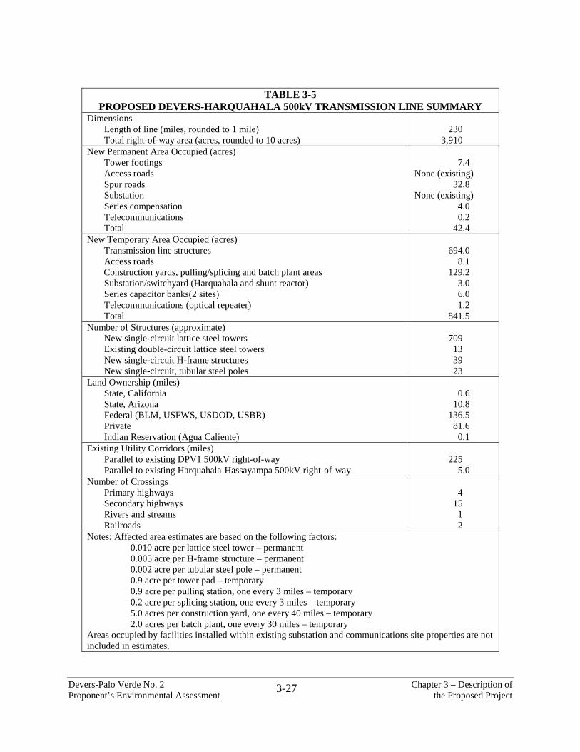
TABLE 3-5 PROPOSED DEVERS-HARQUAHALA 500kV TRANSMISSION LINE SUMMARY
Dimensions Length of line (miles, rounded to 1 mile) Total right-of-way area (acres, rounded to 10 acres)
230 3,910
New Permanent Area Occupied (acres) Tower footings Access roads Spur roads Substation Series compensation Telecommunications Total
New Temporary Area Occupied (acres) Transmission line structures Access roads Construction yards, pulling/splicing and batch plant areas Substation/switchyard (Harquahala and shunt reactor) Series capacitor banks(2 sites) Telecommunications (optical repeater) Total
694.0 8.1 129.2 3.0 6.0 1.2 841.5
Number of Structures (approximate) New single-circuit lattice steel towers Existing double-circuit lattice steel towers New single-circuit H-frame structures New single-circuit, tubular steel poles
709 13 39 23
Land Ownership (miles) State, California State, Arizona Federal (BLM, USFWS, USDOD, USBR) Private Indian Reservation (Agua Caliente)
0.6 10.8 136.5 81.6 0.1
Existing Utility Corridors (miles) Parallel to existing DPV1 500kV right-of-way Parallel to existing Harquahala-Hassayampa 500kV right-of-way
225 5.0
Number of Crossings Primary highways Secondary highways Rivers and streams Railroads
4 15 1 2
Notes: Affected area estimates are based on the following factors: 0.010 acre per lattice steel tower – permanent 0.005 acre per H-frame structure – permanent 0.002 acre per tubular steel pole – permanent 0.9 acre per tower pad – temporary 0.9 acre per pulling station, one every 3 miles – temporary 0.2 acre per splicing station, one every 3 miles – temporary 5.0 acres per construction yard, one every 40 miles – temporary 2.0 acres per batch plant, one every 30 miles – temporary Areas occupied by facilities installed within existing substation and communications site properties are not included in estimates.
Devers-Palo Verde No. 2 Chapter 3 – Description of Proponent’s Environmental Assessment the Proposed Project
3-28
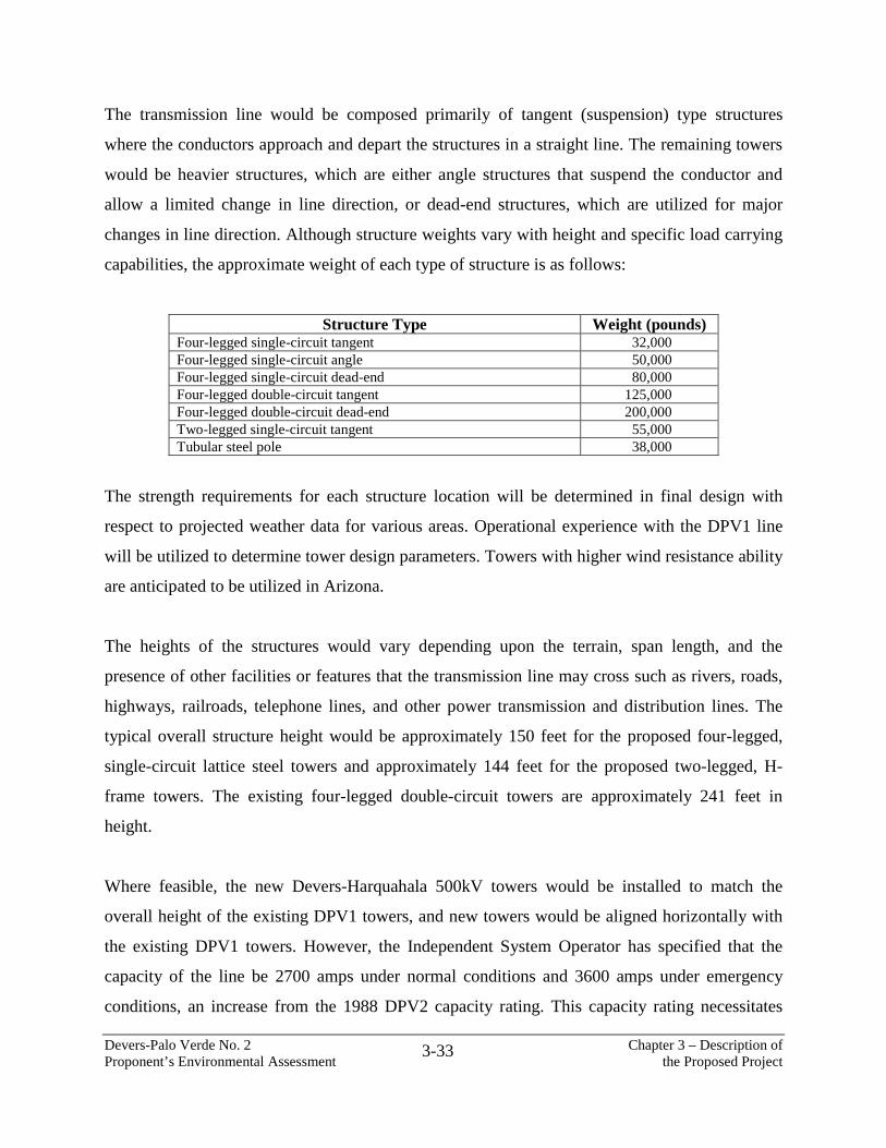
3.3.1.1 Structures
The proposed 500kV transmission line would utilize four types of structures:
The strength requirements for each structure location will be determined in final design with
respect to projected weather data for various areas. Operational experience with the DPV1 line
will be utilized to determine tower design parameters. Towers with higher wind resistance ability
are anticipated to be utilized in Arizona.
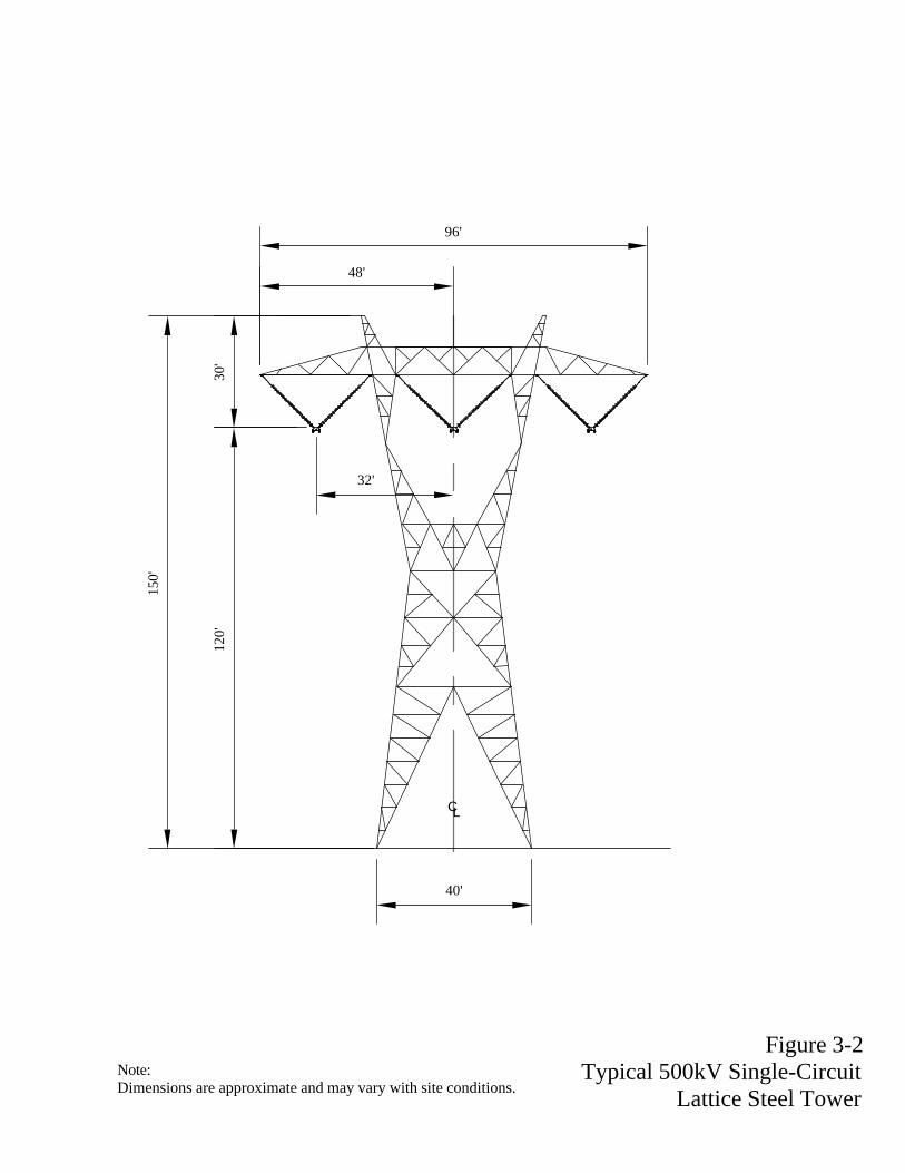
The heights of the structures would vary depending upon the terrain, span length, and the
presence of other facilities or features that the transmission line may cross such as rivers, roads,
highways, railroads, telephone lines, and other power transmission and distribution lines. The
typical overall structure height would be approximately 150 feet for the proposed four-legged,
single-circuit lattice steel towers and approximately 144 feet for the proposed two-legged, H-
frame towers. The existing four-legged double-circuit towers are approximately 241 feet in
height.
Where feasible, the new Devers-Harquahala 500kV towers would be installed to match the
overall height of the existing DPV1 towers, and new towers would be aligned horizontally with
the existing DPV1 towers. However, the Independent System Operator has specified that the
capacity of the line be 2700 amps under normal conditions and 3600 amps under emergency
conditions, an increase from the 1988 DPV2 capacity rating. This capacity rating necessitates
Devers-Palo Verde No. 2 Chapter 3 – Description of Proponent’s Environmental Assessment the Proposed Project
3-34
that the heights of some of the proposed Devers-Harquahala towers be slightly taller than the
adjacent DPV1 structures. In some locations, tower spacing may not correspond to the DPV1
structures, in order to provide adequate conductor ground clearance.
The conductor height also would vary, depending upon the same factors described above for the
structures. The minimum conductor height above ground would be 35 feet between towers.
The typical structure foundations would require four to eight augured, cast-in-place concrete
piles. The size and number of piles required would vary with the type of structure and soil
conditions encountered at each tower site.
The average tower-to-tower spacing (span length) would be approximately 1,550 feet, or about
3.4 towers per mile of line for steel lattice towers. Span lengths generally range from a minimum
of 400 feet to a maximum of 2,200 feet. The typical span length for tubular steel poles would be
1,320 feet, or four towers per mile. The exact quantity and placement of the structures is
determined by the final detailed design of the transmission line, which is influenced by terrain,
land use, environmental resource concerns, and economics.
Some tower locations and site installation conditions may require special tower placement
according to government agency requirements. Special tower placements in these cases would be
coordinated with the appropriate agency.
3.3.1.2 Conductors
Each 500kV phase would be a two-conductor bundle with a spacing of 18 inches between
conductor centers. The typical conductor phase spacing for four-legged single-circuit towers is
32 feet as shown in Figure 3-2; for four-legged double-circuit towers it is 37.5 feet vertically and
45 feet horizontally as shown in Figure 3-3; for two-legged single-circuit towers it is 36.5 feet as
shown in Figure 3-4; and for tubular steel poles it is 15 feet vertically and 32 feet horizontally as
Devers-Palo Verde No. 2 Chapter 3 – Description of Proponent’s Environmental Assessment the Proposed Project
3-35
shown in Figure 3-5. Each conductor is 1.762 inches in diameter, 2,156 kcmil, ACSR. With this
type of conductor, the load current flows through the aluminum strands that are formed in a helix
around the core of steel strands. The steel strands provide the mechanical strength to support the
aluminum strands.
3.3.1.3 Insulators
The tangent and angle 500kV insulator assemblies would consist of two strings of insulators in
the form of a “V.” These strings are used to suspend each conductor bundle (phase) from the
structure while maintaining the electrical clearance between these conductors, the ground, and
the structure. The “V” string also restrains the conductor from swinging into the structure during
winds. Each leg of the “V” assembly would contain one or two one-piece gray polymer
insulators, depending on the conductor loads. On dead-end structures, the insulators are arranged
in a barrel configuration consisting of four polymer insulators. The polymer insulators are
visually similar to the porcelain type insulators used on the DPV1 line, but require less effort to
install and less maintenance.
3.3.1.4 Hardware
Hardware required for the 500kV transmission line would include suspension clamps, dead-end
assemblies, spacers, armor rods, vibration dampers, and other miscellaneous parts. All of the
hardware used on the proposed line would be designed for corona-free operation throughout the
maximum design voltages.
Conductor spacers would be installed along the lines to keep the two-phase subconductors from
contacting each other. This avoids conductor damage due to impacts that would occur without
these spacers. Armor rods would be installed at the points where the suspension clamps support
the conductors. Armor rods increase the safety and reliability of the lines by minimizing the
Devers-Palo Verde No. 2 Chapter 3 – Description of Proponent’s Environmental Assessment the Proposed Project
3-36
possibility of conductor damage resulting from flashovers of the insulator string and by
protecting the conductor mechanically at the support point. Vibration dampers would be located
on the conductor. This helps to prevent metal fatigue of the conductor strands by reducing the
vibration caused by the wind.
3.3.1.5 Overhead Groundwires
The overhead groundwires, located on the peaks of the transmission line structures, are used to
intercept lightning that would otherwise strike the conductors. The 500kV structures would have
two overhead groundwires, approximately 0.5 inch in diameter, supported on each of the two
structure peaks. Any electric current from a lightning strike would be transferred to the ground
through the groundwires and the structure. One of the overhead ground wires would contain
optical fibers for communication and line protection purposes.
3.3.1.6 Right-of-Way
The majority of the right-of-way for the proposed Devers-Harquahala line is located adjacent to
existing 500kV transmission line rights-of-way, including the DPV1 right-of-way for a distance
of approximately 225 miles, and the Harquahala-Hassayampa 500kV transmission line right-of-
way for a distance of 5 miles. The proposed 500kV transmission line would be constructed
within a 130-foot-wide right-of-way on federal and state land, and within a minimum of 130-
foot-wide right-of-way on private land and Indian Reservation land, where located adjacent to
the existing DPV1 right-of-way (Figure 3-6). In 1989, the BLM granted a right-of-way to SCE
for the DPV2 transmission line, which includes land managed by the BLM and USFWS as
shown in Table 3-2. The proposed Devers-Harquahala 500kV line would be constructed within
that right-of-way previously granted by the BLM.
100'
130'
200'
DEVERS - PALO VERDE NO. 1 500kV
80'
130'
290'
EXISTING DEVERS - PALO VERDE NO. 1 RIGHT-OF-WAY
DEVERS - PALO VERDE NO. 1 500kV
80' DEVERS -
HARQUAHALA 500kV
STRUCTURE FOOTPRINT
STRUCTURE FOOTPRINT
DEVERS - HARQUAHALA RIGHT-OF-WAY
160'
130'
100' DEVERS -
HARQUAHALA 500kV
EXISTING DEVERS - PALO VERDE NO. 1 RIGHT-OF-WAY
DEVERS - HARQUAHALA RIGHT-OF-WAY13
0'
330'
EXISTING
PROPOSED
PROPOSED
EXISTING
TYPICAL RIGHT-OF-WAY ADJACENT TO DPV1 ON BLM AND ARIZONA STATE LAND
TYPICAL RIGHT-OF-WAY ADJACENT TO DPV1 ON PRIVATE LAND, INDIAN RESERVATION, AND CALIFORNIA STATE LAND
Figure 3-6Typical Devers-Harquahala 500kV
Transmission Line Right-of-Way
Devers-Palo Verde No. 2 Chapter 3 – Description of Proponent’s Environmental Assessment the Proposed Project
3-38
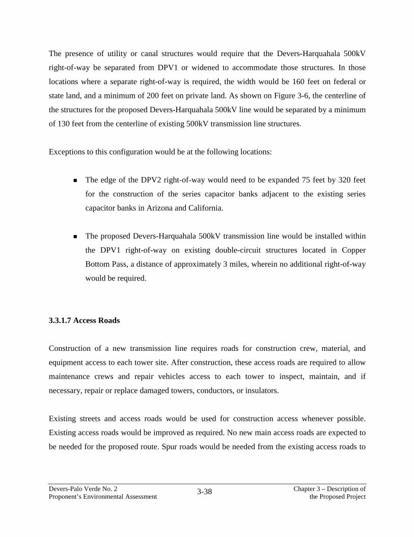
The presence of utility or canal structures would require that the Devers-Harquahala 500kV
right-of-way be separated from DPV1 or widened to accommodate those structures. In those
locations where a separate right-of-way is required, the width would be 160 feet on federal or
state land, and a minimum of 200 feet on private land. As shown on Figure 3-6, the centerline of
the structures for the proposed Devers-Harquahala 500kV line would be separated by a minimum
of 130 feet from the centerline of existing 500kV transmission line structures.
Exceptions to this configuration would be at the following locations:
The edge of the DPV2 right-of-way would need to be expanded 75 feet by 320 feet
for the construction of the series capacitor banks adjacent to the existing series
capacitor banks in Arizona and California.
The proposed Devers-Harquahala 500kV transmission line would be installed within
the DPV1 right-of-way on existing double-circuit structures located in Copper
Bottom Pass, a distance of approximately 3 miles, wherein no additional right-of-way
would be required.
3.3.1.7 Access Roads
Construction of a new transmission line requires roads for construction crew, material, and
equipment access to each tower site. After construction, these access roads are required to allow
maintenance crews and repair vehicles access to each tower to inspect, maintain, and if
necessary, repair or replace damaged towers, conductors, or insulators.
Existing streets and access roads would be used for construction access whenever possible.
Existing access roads would be improved as required. No new main access roads are expected to
be needed for the proposed route. Spur roads would be needed from the existing access roads to
Devers-Palo Verde No. 2 Chapter 3 – Description of Proponent’s Environmental Assessment the Proposed Project
3-39
the new tower sites. Some existing access roads deviate from the right-of-way in order to avoid
environmentally sensitive areas or rough land terrain features, such as steep hillside slopes.
Access and spur roads are generally 14-foot-wide unimproved roads. The main access road
follows the transmission line right-of-way with spur roads branching off to each tower site. Spur
roads usually have turnabout areas near the tower sites. All access road and spur road
improvements, whether on or off the right-of-way, would satisfy all applicable permits and
regulations.
3.3.2 West of Devers 230kV Transmission System Facilities
The proposed DPV2 project would require upgrades to SCE’s existing 230kV transmission
system west of Devers. The existing 230kV system west of Devers includes two 230kV circuits
connecting Devers and Vista substations and two circuits connecting Devers with the San
Bernardino Substation located at the San Bernardino Generating Station (Figure 3-7a). San
Bernardino Junction is the term used to identify the intersection of the 230kV transmission line
corridors that meet 3.4 miles south of the San Bernardino Substation.
The existing 230kV transmission system upgrade segment from Devers to San Bernardino
Junction is approximately 40 miles. The segment from Vista Substation to San Bernardino
Junction is approximately 4.8 miles. The segment from San Bernardino Substation to San
Bernardino Junction is approximately 3.4 miles. The upgrades required for the 230kV system
include the following, as shown on Figure 3-7a:
Removal of an existing 40-mile, single-circuit wood H-frame 230kV line between Devers
and San Bernardino Junction.
Removal of an existing 40-mile, single-circuit lattice steel 230kV line between Devers
and San Bernardino Junction.
Figure 3-7aWest of Devers 230kV System, Existing and Proposed
Devers-Palo Verde No. 2 Chapter 3 – Description of Proponent’s Environmental Assessment the Proposed Project
3-41
Construction of a new 40-mile, double-circuit 230kV line between Devers and San
Bernardino Junction within the existing right-of-way.
Reconductoring of and modification to the existing 40-mile, double-circuit 230kV lattice
steel tower line between the Devers Substation and San Bernardino Junction.
Reconductoring both circuits on an existing 4.8-mile, double-circuit 230kV lattice steel
tower line between Vista Substation and San Bernardino Junction.
Reconductoring one circuit on each of the two existing 3.4-mile, double-circuit 230kV
lattice steel tower lines between San Bernardino Substation and San Bernardino Junction.
Each of the 230kV transmission lines is designed to operate at a nominal voltage of 230kV phase
to phase. When the upgrades are completed, each 230kV circuit would be capable of transferring
nominally 988 MW of power on a continual basis and 1,335 MW under emergency conditions.
A summary of the proposed west of Devers 230kV transmission facilities is provided in Table 3-
6.
TABLE 3-6 PROPOSED WEST OF DEVERS 230kV UPGRADE SUMMARY
Length of segment from Devers Substation to San Bernardino Junction
40 miles
Length of segment from Vista Substation to San Bernardino Junction
4.8 miles
Length of segment from San Bernardino Substation to San Bernardino Junction
3.4 miles
Span length (spacing between towers) 1,400 to 1,500 feet 3.5 to 3.8 structures/mile (average)
Number of existing structures removed 398 Total number of new structures to be installed 161 Number of existing structures to be raised 23 Number of existing structures to be reinforced 37 Area affected by structure removal 9.7 acres Area affected by new structure installation 46.7 acres Area affected by pulling/splicing sites 27.5 acres Affected area estimates based on the following factors:
0.06 acre per each structure removed - temporary 0.29 acre per new structure installed - permanent 14-foot-wide by 200 feet long spur roads at 25 percent of new tower sites - permanent 0.6 acre/mile pulling/splicing sites - temporary
Devers-Palo Verde No. 2 Chapter 3 – Description of Proponent’s Environmental Assessment the Proposed Project
3-42
3.3.2.1 Structures
The proposed 230kV transmission system modifications include utilization of the existing
double-circuit lattice steel towers between Devers and Vista substations, and between the San
Bernardino Substation and San Bernardino Junction. The new double-circuit line between
Devers and San Bernardino Junction would be constructed on lattice steel structures similar in
size and appearance to the existing structures. It is estimated that 23 existing lattice steel towers
may be raised with the use of a lattice steel extension set under the existing structures using new
concrete foundations. Some new structures may be inter-set between existing towers, as required,
to support new conductors.
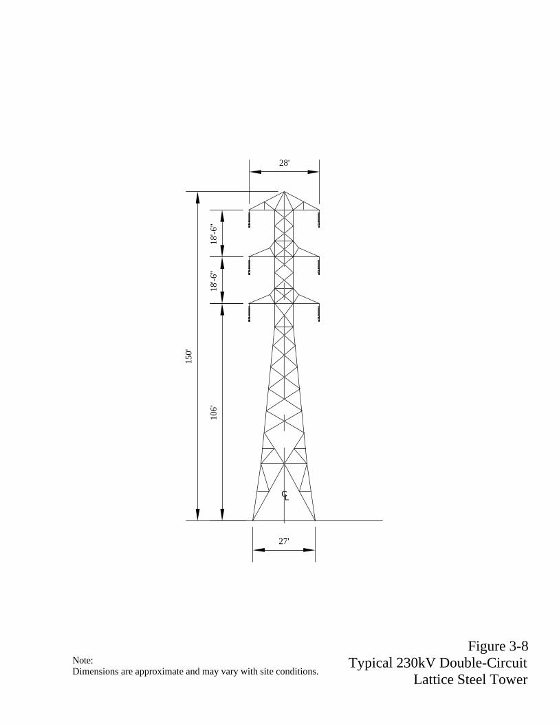
The existing and proposed structure configuration and placements are shown on Figures 3-7b
through 3-7e. Lattice towers, shown in Figure 3-8, would be constructed of galvanized steel
angle members connected with bolts. Each tower would support two circuits consisting of three
phases of conductors arranged in a vertical configuration.
The new double-circuit transmission line would be constructed using primarily tangent
(suspension) type structures where the conductors approach and depart the structures in the same
straight line. The remaining towers are heavier structures, which are either angle structures
which permit limited changes in line direction, or deadend structures which are utilized for major
changes in line direction. Although structure weights vary with their height and specific load
carrying capabilities, the approximate weight of each type of structure is as follows:
SECTION A-A EXISTING RIGHT-OF-WAY LOOKING WEST
(Refer to Figure 3-7a)
SECTION A-A PROPOSED RIGHT-OF-WAY LOOKING WEST
(Refer to Figure 3-7a)
DEVERS-SAN BERNARDINO NO.1 230kV
DEVERS-VISTA NO.2 230kV
DEVERS-SAN BERNARDINO NO.2 230kV
DEVERS - BANNING - WINPARK - ZANJA
115kVDEVERS-VISTA NO.1 230kV
100' VARIES
50' MIN.
300'
50' 50' VARIES VARIES 100' 100' 100'
EXISTING RIGHT-OF-WAY
DEVERS - BANNING - WINPARK - ZANJA 115kV
DEVERS-VISTA NO.2 230kV
DEVERS-VISTA NO.1 230kV
DEVERS-SAN BERNARDINO-
NO.1 230kV (RECONDUCTORED
DEVERS-SAN BERNARDINO NO.2 230kV (RECONDUCTORED)
VARIESVARIES50'50' 200' 100'
PROPOSED RIGHT-OF-WAY
Figure 3-7bTypical Sections
SECTION B-BEXISTING RIGHT-OF-WAY LOOKING WEST
(Refer to Figure 3-7a)
SECTION B-BPROPOSED RIGHT-OF-WAY LOOKING WEST
(Refer to Figure 3-7a)
DEVERS-SAN BERNARDINO NO.2 230kV
DEVERS-VISTA NO.2 230kV
DEVERS-VISTA NO.1 230kV
DEVERS-SAN BERNARDINO NO.1 230kV
100' 100' 150' MINIMUM 50'
EXISTING RIGHT-OF-WAY
DEVERS-VISTA NO.1 230kV
(RECONDUCTORED)
DEVERS-VISTA NO.2 230kV (RECONDUCTORED)
DEVERS-SAN BERNARDINO
NO.1 230kV
DEVERS-SAN BERNARDINO NO.2 230kV
50'150' MINIMUM200'
PROPOSED RIGHT-OF-WAY
Figure 3-7cTypical Sections
50' 50'50'
50' 50'50'
EXISTING RIGHT-OF-WAY
PROPOSED RIGHT-OF-WAY
DEVERS-SAN BERNARDINONO. 1 230kV
DEVERS-SAN BERNARDINONO. 2 230kV
SAN BERNARDINO-VISTA 230kV ETIWANDA-SAN BERNARDINO 230kV
SECTION C-CEXISTING RIGHT-OF-WAY LOOKING NORTH
(Refer to Figure 3-7a)
SECTION C-CPROPOSED RIGHT-OF-WAY LOOKING NORTH
(Refer to Figure 3-7a)
ETIWANDA-SAN BERNARDINO 230kV
DEVERS-SAN BERNARDINONO. 2 230kV (RECONDUCTORED)
SAN BERNARDINO-VISTA 230kV
DEVERS-SAN BERNARDINO NO. 1 230kV
(RECONDUCTORED)
Figure 3-7dTypical Sections
300'-325' TYPICAL 100' TYPICAL75'-100' TYPICAL
EXISTING RIGHT-OF-WAY
DEVERS-VISTANO. 2 230kV
SECTION D-DEXISTING RIGHT-OF-WAY LOOKING WEST
(Refer to Figure 3-7a)
DEVERS-VISTANO. 1 230kV
SAN BERNARDINO-VISTANO. 2 230kV
ETIWANDA-SAN BERNARDINONO. 1 230kV
SECTION D-DPROPOSED RIGHT-OF-WAY LOOKING WEST
(Refer to Figure 3-7a)
PROPOSED RIGHT-OF-WAY
75'-100' TYPICAL 100' TYPICAL300'-325' TYPICAL
DEVERS-VISTA NO. 2 230kV (RECONDUCTORED)
DEVERS-VISTA NO. 1 230kV (RECONDUCTORED)
SAN BERNARDINO-MARASCHINO
115kV
VALLEY-MAYBERRY-MORENO-VISTA
115kV
VALLEY-MAYBERRY-MORENO-VISTA
115kV
SAN BERNARDINO-MARASCHINO
115kV
SAN BERNARDINO-VISTANO. 2 230kV
ETIWANDA-SAN BERNARDINONO. 1 230kV
Figure 3-7eTypical Sections
150'
27'
106'
18'-6
"18
'-6"
28'
CL
Figure 3-8Typical 230kV Double-Circuit
Lattice Steel Tower Note:Dimensions are approximate and may vary with site conditions.
Devers-Palo Verde No. 2 Chapter 3 – Description of Proponent’s Environmental Assessment the Proposed Project
would be utilized wherever feasible. If no such facilities exist in certain areas, temporary
concrete batch plants would be set up in areas approved by the authorizing agency. Concrete
Devers-Palo Verde No. 2 Chapter 3 – Description of Proponent’s Environmental Assessment the Proposed Project
3-73
would be hauled to the structure site from the concrete supply facilities in standard concrete
trucks. Care would be taken to minimize damage to the existing landscape and natural
vegetation. Disposal of unused concrete would be restricted to methods detailed in the
stormwater pollution prevention plan.
Counterpoise may need to be installed if the local soil conditions indicate that the soil has a
resistance above 30 ohms. This is accomplished by attaching a 0.375-inch cable to the tower
steel. The cable is installed 1-foot underground and extends approximately 100 feet (within the
right-of-way) from two or more footings.
3.5.6.2 West of Devers 230kV Upgrade
The proposed 230kV modifications for the west of Devers system would require the construction
of foundations for approximately 161 structures. Foundation installation for the 230kV upgrade
would be similar to that of the 500kV segment as described above.
3.5.7 Structure Assembly and Erection
3.5.7.1 Devers-Harquahala 500kV Segment and West of Devers 230kV Upgrade
At the structure fabrication plant, structural members would be assembled into bundles, shipped
by rail or truck to the construction yards, and then trucked to the individual sites. After being
assembled into subassemblies, the subassemblies would be put together with the aid of a crane.
Assembly and erection of the structures required for the proposed transmission line would
consist of three main activities: (1) assembly of main sections, (2) erection of the sections, and
(3) final cleanup. Sections would be joined together with the aid of a crane and erected on
Devers-Palo Verde No. 2 Chapter 3 – Description of Proponent’s Environmental Assessment the Proposed Project
3-74
foundations. Installation of insulators and travelers and final checkout and cleanup would then
conclude structure assembly and erection.
3.5.8 Conductor and Overhead Groundwire Stringing
3.5.8.1 Devers-Harquahala 500kV Segment and West of Devers 230kV Upgrade
The stringing of conductor and overhead groundwire on new transmission lines would normally
commence once a suitable number of structures had been erected and inspected. Setup locations
for stringing equipment located between suspension towers would be temporary 150-foot by
300-foot areas located adjacent to the access roads approximately every 5,000 to 15,000 feet
along the line. Smaller setup areas, 100 feet by 200 feet, are possible near either side of dead-end
structures. Geographic, environmental, and cultural factors will determine the final locations of
setup locations. Other considerations include specific line design issues such as locations of
dead-end structures or line direction changes.
To shield underlying activities and facilities, temporary netting systems or wood pole guard
structures would be erected at crossings for roads, streets, railroads, highways, or other
transmission, distribution, or communication facilities, as required, prior to stringing operations.
On roads where traffic is light, guard structures may not be necessary; however, the use of
barriers, flagmen and/or temporary stopping of traffic would be required.
Conductor is usually supplied on 96-inch reels in lengths of up to 7,500-foot reels. Groundwire is
usually supplied on reels in 15,000-foot lengths. For new transmission lines, stringing initially
would consist of flying in pilot lines (small and lightweight) through the stringing travelers by
helicopter, subsequently pulling larger steel cable. The conductor or groundwire would then be
pulled from the established setup points by wire stringing equipment. For reconductor of existing
lines and overhead groundwire west of Devers Substation, stringing would initially consist of
replacing insulators, installing travelers, then transferring the existing conductor to the installed
Devers-Palo Verde No. 2 Chapter 3 – Description of Proponent’s Environmental Assessment the Proposed Project
3-75
travelers. The existing conductor or groundwire would then be pulled out from the established
setup points. The new conductor or groundwire would be pulled in. The conductor or groundwire
would then be transferred into suspension hardware.
3.5.9 Removal of Facilities, West of Devers 230kV Upgrade
Two existing single-circuit transmission lines would be removed between Devers Substation and
San Bernardino Junction. Guard structures would be erected for the conductor removal activities.
In accordance with prearranged outages, facilities would be taken off line, conductor would be
removed, and structures disassembled and hauled to staging yards for disposal. Guard structures
would then be disassembled and removed. Removal would be coordinated with new line
construction, structure rearrangement, and reconductor work. Materials would be recycled where
feasible.
3.5.10 Telecommunications Facilities
3.5.10.1 Harquahala Mountain
Contractors and subcontractors would be used to construct the new building and antenna tower.
A medium duty crane would be required for the construction of the antenna tower. SCE’s
telecommunications construction crews will be used for telecommunications equipment
installation.
Three trucks and six men would be needed during peak construction periods. Construction of the
new facility and antenna tower will take approximately 12 to 16 weeks to complete and would
consist of the following steps:
Devers-Palo Verde No. 2 Chapter 3 – Description of Proponent’s Environmental Assessment the Proposed Project
3-76
site preparation
erect temporary fencing area
set the foundations
install prefab building, fuel tanks, and emergency generator
install photovoltaic (solar) system
erect the antenna tower
install antennas and telecommunications equipment
erect permanent fencing
site cleanup
The prefabricated building would be pre-assembled at the manufacturing plant and delivered to
the Harquahala Mountain. The building would be set on a concrete pad using a crane. The
antenna tower will be assembled and erected on site. Each tower section would be erected using
a crane.
3.5.10.2 Blythe Optical Repeater
Contractors and subcontractors would be used to construct the new building. SCE’s
telecommunications construction crews will be used for telecommunications equipment
installation.
Three trucks and six men would be needed during peak construction periods. Construction of the
new facility and antenna tower will take approximately 10 to 12 weeks to complete and would
consist of the following steps:
site preparation
erect temporary fencing area
set the foundations
install prefab building, fuel tanks, and emergency generator
Devers-Palo Verde No. 2 Chapter 3 – Description of Proponent’s Environmental Assessment the Proposed Project
3-77
install telecommunications equipment
erect permanent fencing
site cleanup
The prefabricated building would be pre-assembled at the manufacturing plant and delivered to
the job site. The building would be set on a concrete pad using a crane.
3.5.11 Post-Construction Cleanup
During construction, all excess materials would be removed from the right-of-way. After
construction, all debris would be disposed of in a manner such that the area would be returned as
near as practicable to its pre-construction appearance. This would include removal of surplus
buildings and equipment, lumber, refuse, fencing, and all other items not at the sites prior to
construction.
3.6 OPERATION AND MAINTENANCE
3.6.1 Schedule
Following completion of project construction, operation and maintenance of the new lines would
commence. Inspection and maintenance activities would include the following:
routine line patrols by both aircraft and truck
routine, patrol identified, tower and wire maintenance
routine line washing
routine, patrol identified, earth and sand abatement from footings
routine right-of-way road maintenance
Devers-Palo Verde No. 2 Chapter 3 – Description of Proponent’s Environmental Assessment the Proposed Project
3-78
The frequency of inspection and maintenance would depend on various conditions including
length of the line and weather effects. Schedules by line are summarized in Table 3-9.
3.6.2 Labor Force Requirements
Inspection and maintenance activities typically include senior patrolman, foreman, lead lineman,
journeyman lineman, apprentices, groundmen, helicopter pilots, equipment operators, and
laborers. If the magnitude of repairs identified by routine patrols is substantial, other specialized
employees such as surveyors, engineers, clerical personnel, and technicians would be attached to
maintenance crews as required to address any unique problem that may arise due to such
variables as substantial storm damage or vandalism. Labor force requirements by line are
summarized in Table 3-9.
For the Devers-Harquahala 500kV line, it is expected that there would be a minor increase in
operation and maintenance activity compared to the existing operation and maintenance activity
along the existing corridor. No significant increase in patrols or grading would be required.
For the west of Devers upgrade, it is expected that there will be a small decrease in operation and
maintenance activity because there would be a reduced number of structures to patrol or maintain
and the use of polymer insulators would significantly reduce or nearly eliminate the need for
insulator washing.
Devers-Palo Verde No. 2 Chapter 3 – Description of Proponent’s Environmental Assessment the Proposed Project
3-79
TABLE 3-9 OPERATION AND MAINTENANCE LABOR FORCE
Activity Frequency Duration Personnel Required Note Devers-Harquahala 500kV Transmission Line
Routine Patrol, Aircraft Every two years 8 hours Pilot x 1 Senior Patrolman x 1 Lineman x 1
Routine Patrol, Truck Every two years 3 weeks Senior Patrolman x 1 Lineman x 2
Lines are patrolled annually; patrol alternates yearly between helicopter and truck.
Routine repairs identified by Senior Patrolman
Every year 10 days Foreman x 3
Senior Lineman x 3 Lead Lineman x 3 Journeyman Lineman x 6 Apprentice x 6 Groundmen x 3 Equipment Operator x 3
Laborer x 3
Repair unique items identified by senior patrolman during annual patrols, varies year to year. As many as three 8-man crews plus operators.
Remove Windblown Sand from Tower Footings
Every two years 1 week Foreman x 1
Equipment Operator x 1 Laborer x 1
Windblown sand and earth removed from LST steel by contract crew under direction of senior patrolman.
Routine Right-of-Way Grading Every three years 2 months Foreman x 1 Equipment Operator x 1 Laborer x 1
Grade all approved areas only.
Routine Washing N/A N/A N/A Wash insulators as required.
West of Devers 230kV Transmission System Routine Patrol, Aircraft Seldom 8 hours Pilot x 1
Senior Patrolman x 1 Lineman x 1
Routine Patrol, Truck Every year 1 week Senior Patrolman x 1 Lineman x 1
Lines are patrolled annually; patrol alternates yearly between helicopter and truck.
Routine repairs identified by Senior Patrolman
Every year 3 days Foreman x 1
Senior Lineman x 1 Lead Lineman x 1 Journeyman Lineman x 2 Apprentice x 2 Groundmen x 1 Equipment Operator x 1
Laborer x 1
Repair unique items identified by senior patrolman during annual patrols, varies year to year. One 8-man crew plus operators.
Routine Right-of-Way Grading Every year 2 months Foreman x 1 Equipment Operator x 1 Laborer x 1
Grade all approved areas only.
Washing NA NA NA NA
Wash insulators as required.
Devers-Palo Verde No. 2 Chapter 3 – Description of Proponent’s Environmental Assessment the Proposed Project
3-80
3.6.3 System Operation and Maintenance Procedures
Maintenance of the proposed transmission lines would consist of periodic patrols by ground and
air to locate any damage that might adversely affect the integrity and reliability of the line. Other
non-emergency maintenance would involve the occasional replacement of insulators damaged by
lightning or gunfire, the replacement of tower steel members due to gunfire or wind, and the
repair of access and stub roads due to erosion or landslides. Crews would wash insulators, as
necessary, using a specialized truck for the 230kV lines west of Devers. In the future, if levels of
air pollution increase, the 500kV lines east of Devers Substation would require washing as well.
Crews also would remove windblown sand and dirt from footings in areas where it has a
tendency to accumulate.
3.7 SAFETY CONSIDERATIONS
3.7.1 Design
Safety is one of the primary considerations in the design of the proposed transmission line
project. The proposed DPV2 transmission lines would be protected at the substations with circuit
breakers that are connected to the protective relay system to minimize the possibility of electrical
shock or fire in the event of either a single or multiple conductor breakage. Lightning protection
would be provided by overhead groundwires along the lines.
In accordance with good safety practice, all fences and metal gates, either within or crossing the
right-of-way, would be grounded.
Devers-Palo Verde No. 2 Chapter 3 – Description of Proponent’s Environmental Assessment the Proposed Project
3-81
3.7.2 Construction
Safety-related measures proposed as part of the construction phase activities are listed below:
Construction operations would be conducted in a manner to avoid closing or obstructing
railroads, roads, or other property until the appropriate permits have been obtained from
landowners, governmental agencies, or other authorities having jurisdiction.
Vehicular construction traffic would be limited to approved access roads, construction
yards, and construction sites. No off-road travel would be permitted.
Construction foremen and personnel would be well informed as to where construction
equipment and vehicles would be permitted.
Fences that cross the proposed transmission system access roads would be gated or
modified per agreements with the landowner.
No work would be performed that would affect any existing pipeline, telephone, telegraph
or electric line, irrigation ditch, or other structure until proper authorization has been
obtained.
All applicable fire laws and regulations of the land-management agency with jurisdiction
over land crossed by the proposed project would be fully complied with, and all fire plans
would be followed.
Construction-related areas would be maintained in a neat, clean, and sanitary condition at
all times.
Each tower site would be kept free from accumulation of waste materials and rubbish as
required for safety, appearance, and prevention of fire hazards.
Devers-Palo Verde No. 2 Chapter 3 – Description of Proponent’s Environmental Assessment the Proposed Project
3-82
3.7.3 Operation and Maintenance
In case of single or multiple conductor failure, power would be automatically and rapidly
removed from the lines to minimize the possibility of electrical shock or fire.
3.8 PROJECT ECONOMICS
3.8.1 Construction Costs
The estimated nominal cost for the construction of the proposed DPV2 transmission line project
including right-of-way and related facilities, substation and series capacitors, voltage support,
and telecommunication facilities is approximately $591 million. The estimated cost breakdown
by individual project elements is summarized in Table 3-10.
TABLE 3-10 SUMMARY OF ESTIMATED CONSTRUCTION COSTS
FOR THE DEVERS-PALO VERDE 2 PROJECT (2005 dollars)
Elements Total Element Costs
(x $1,000) TRANSMISSION LINE 500kV Transmission Line 230kV Transmission Line Series Capacitors
Subtotal Transmission Line
$ 246,000 $ 97,000 $ 31,000 $ 374,000
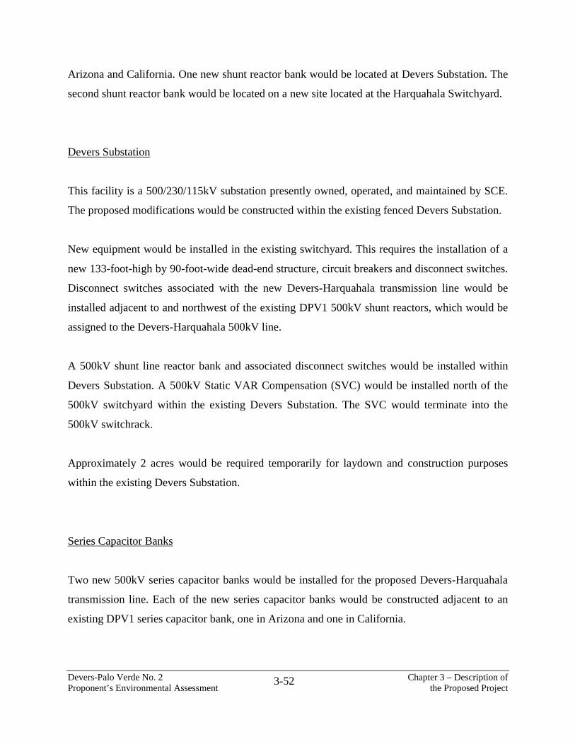
SUBSTATION AND RELATED FACILITIES Substation Construction
Voltage Support Special Protection Scheme
Telecommunications Subtotal Substation and Related Facilities
$ 116,000 $ 72,000 $ 3,000 $ 14,000 $ 205,000
LAND $ 12,000 TOTAL PROJECT COST $ 591,000 NOTE: This estimate includes pension, benefits, and administrative and general overhead, but does not include Allowance for Funds Used During Construction (AFUDC).
Devers-Palo Verde No. 2 Chapter 3 – Description of Proponent’s Environmental Assessment the Proposed Project
3-83
3.9 DECOMMISSIONING
It is expected that the proposed transmission line would have a useful life of at least 50 years.
Decommissioning plans, therefore, have not been developed at this time.
Devers-Palo Verde No. 2 Chapter 3 – Description of Proponent’s Environmental Assessment the Proposed Project
3-84
Map 3-2a
DEVERS-HARQUAHALA 500kV PROPOSED AND SUBALTERNATIVE ROUTES
Devers-Palo Verde No. 2 Chapter 3 – Description of Proponent’s Environmental Assessment the Proposed Project
3-85
Map 3-2b
DEVERS-HARQUAHALA 500kV PROPOSED AND SUBALTERNATIVE ROUTES
Devers-Palo Verde No. 2 Chapter 3 – Description of Proponent’s Environmental Assessment the Proposed Project
3-86
Map 3-2c
DEVERS-HARQUAHALA 500kV PROPOSED AND SUBALTERNATIVE ROUTES
Devers-Palo Verde No. 2 Chapter 3 – Description of Proponent’s Environmental Assessment the Proposed Project