CHAPTER 3 Computer Assembly—Step by Step Objectives Upon completion of this chapter, you should be able to answer the following questions: ■ How do I open the case? ■ What is the process to install the power supply? ■ How do I attach the components to the motherboard and install the motherboard? ■ How do I install internal drives? ■ How do I install drives in external bays? ■ How do I install adapter cards? ■ What is the process to connect all internal cables? ■ How do I reattach the side panels and connect external cables to the computer? ■ What happens when I boot the computer for the first time? Key Terms This chapter uses the following key terms. You can find the definitions in the Glossary. electrostatic discharge (ESD) page 80 power supply page 80 motherboard page 81 central processing unit (CPU) page 82 zero insertion force (ZIF) socket page 83 thermal compound page 83 isopropyl alcohol page 83 heat sink/fan assembly page 83 random-access memory (RAM) page 83 volatile memory page 85 hard disk drive (HDD)[em]page 86 optical drive page 86 floppy disk drive (FDD) page 86 Molex power connector page 86 Berg power connector page 87 adapter card page 88 network interface card (NIC) page 88 video adapter card page 89 Advanced Technology Extended (ATX) page 91 Serial Advanced Technology Attachment (SATA) power connector page 91 Parallel Advanced Technology Attachment (PATA) Data cable page 92 Serial Advanced Technology Attachment (SATA) data cable page 92 basic input/output system (BIOS)[em]page 96 beep code page 97 complementary metal-oxide semiconductor (CMOS) page 97 9781587132636_ch03.qxp 8/20/10 1:37 PM Page 79 DRAFT
Transcript
CHAPTER 3
Computer Assembly—Step by Step
ObjectivesUpon completion of this chapter, you should be able to answer the following questions:
n How do I open the case?
n What is the process to install the power supply?
n How do I attach the components to the motherboard and install the motherboard?
n How do I install internal drives?
n How do I install drives in external bays?
n How do I install adapter cards?
n What is the process to connect all internalcables?
n How do I reattach the side panels and connectexternal cables to the computer?
n What happens when I boot the computer for thefirst time?
Key TermsThis chapter uses the following key terms. You can find the definitions in the Glossary.
electrostatic discharge (ESD) page 80
power supply page 80
motherboard page 81
central processing unit (CPU) page 82
zero insertion force (ZIF) socket page 83
thermal compound page 83
isopropyl alcohol page 83
heat sink/fan assembly page 83
random-access memory (RAM) page 83
volatile memory page 85
hard disk drive (HDD)[em]page 86
optical drive page 86
floppy disk drive (FDD) page 86
Molex power connector page 86
Berg power connector page 87
adapter card page 88
network interface card (NIC) page 88
video adapter card page 89
Advanced Technology Extended (ATX) page 91
Serial Advanced Technology Attachment (SATA)power connector page 91
Assembling computers is a large part of a technician’s job. As a technician, you will need towork in a logical, methodical manner when working with computer components. As withany learned trade, your computer assembly skills will improve dramatically with practice.
Open the CaseComputer cases are produced in a variety of form factors. Form factors refer to the size andshape of the case.
Prepare the workspace before opening the computer case. There should be adequate light-ing, good ventilation, and a comfortable room temperature. The workbench or table shouldbe accessible from all sides. Avoid cluttering the surface of the workbench or table withtools and computer components. An antistatic mat on the table will help prevent physicaland electrostatic discharge (ESD) damage to equipment. Small containers can be used tohold small screws and other parts as they are being removed.
There are different methods for opening cases. To learn how to open a particular computercase, consult the user manual or the manufacturer’s website. Most computer cases areopened in one of the following ways:
n The computer case cover can be removed as one piece.
n The top and side panels of the case can be removed.
n The top of the case may need to be removed before the side panels can be removed.
n Tool-less entries allow technicians to enter a case without the use of tools.
Install the Power SupplyA technician may be required to replace or install a power supply, as shown in Figure 3-1.Most power supplies can fit into the computer case in only one way. There are usually threeor four screws that attach the power supply to the case. Power supplies have fans that canvibrate and loosen screws that are not secured. When installing a power supply, make surethat all of the screws are used and that they are properly tightened.
These are the power supply installation steps:
Step 1. Insert the power supply into the case.
Step 2. Align the holes in the power supply with the holes in the case.
Step 3. Secure the power supply to the case using the proper screws.
80 IT Essentials: PC Hardware and Software Companion Guide
How To
9781587132636_ch03.qxp 8/20/10 1:37 PM Page 80
DRAFT
Figure 3-1 Power Supply
Chapter 3: Computer Assembly—Step by Step 81
Virtual Desktop Activity: Power Supply
Complete the power supply layer in the Virtual Desktop. Refer to the Virtual Desktop soft-ware on the CD that comes with this book.
Virtual Desktop Activity: Motherboard
System requirements for the Virtual Desktop include a minimum of 512 MB RAM andWindows 2000 or Windows XP operating system.
Lab 3.2.0: Install the Power Supply
In this lab, you install the power supply in the computer. Refer to the lab in IT Essentials:PC Hardware and Software Lab Manual, Fourth Edition. You may perform this lab now orwait until the end of the chapter.
Attach the Components to the Motherboardand Install the MotherboardThis section details the steps to install components on the motherboard and then install themotherboard into the computer case.
After completing this section, you will meet these objectives:
n Install a CPU and a heat sink/fan assembly.
n Install the RAM.
n Install the motherboard.
9781587132636_ch03.qxp 8/20/10 1:37 PM Page 81
DRAFT
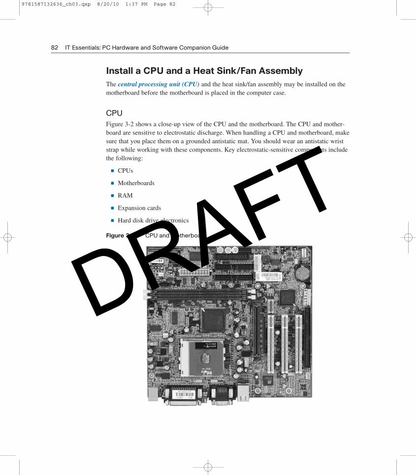
Install a CPU and a Heat Sink/Fan AssemblyThe central processing unit (CPU) and the heat sink/fan assembly may be installed on themotherboard before the motherboard is placed in the computer case.
CPUFigure 3-2 shows a close-up view of the CPU and the motherboard. The CPU and mother-board are sensitive to electrostatic discharge. When handling a CPU and motherboard, makesure that you place them on a grounded antistatic mat. You should wear an antistatic wriststrap while working with these components. Key electrostatic-sensitive components includethe following:
n CPUs
n Motherboards
n RAM
n Expansion cards
n Hard disk drive electronics
Figure 3-2 CPU and Motherboard
82 IT Essentials: PC Hardware and Software Companion Guide
9781587132636_ch03.qxp 8/20/10 1:37 PM Page 82
DRAFT
CautionWhen handling a CPU, do not touch the CPU contacts at any time.
The CPU is secured to the socket on the motherboard with a locking assembly. The CPUsockets today are zero insertion force (ZIF) sockets. You should be familiar with the lock-ing assembly before attempting to install a CPU into the socket on the motherboard. Orientthe missing pin in the corner of the CPU to the missing hole on the socket.
Thermal compound helps to conduct heat away from the CPU. Figure 3-3 shows thermalcompound being applied to the CPU.
Figure 3-3 Thermal Compound on the CPU
Chapter 3: Computer Assembly—Step by Step 83
CautionSilver-oxide thermal compound is toxic. Use rubber gloves and wash your hands thoroughly after-ward. It does not take very much compound to fill the space between the CPU and heat sink. If youuse too much it will leak onto the motherboard.
When you are installing a used CPU, clean the CPU and the base of the heat sink withisopropyl alcohol. Doing this removes all traces of old thermal compound. The surfaces arenow ready for a new layer of thermal compound. Follow all manufacturer recommendationsabout applying the thermal compound.
Heat Sink/Fan AssemblyFigure 3-4 shows the connector and the motherboard header for the heat sink/fan assembly.It is a two-part cooling device. The heat sink draws heat away from the CPU. The fanmoves the heat away from the heat sink. The heat sink/fan assembly usually has a 3-pinpower connector.
9781587132636_ch03.qxp 8/20/10 1:37 PM Page 83
DRAFT
Figure 3-4 Heat Sink/Fan Assembly on the Motherboard
84 IT Essentials: PC Hardware and Software Companion Guide
Follow these instructions for CPU and heat sink/fan assembly installation:
Step 1. Align the CPU so that the Connection 1 indicator is lined up with Pin 1 on theCPU socket. Doing this ensures that the orientation notches on the CPU arealigned with the orientation keys on the CPU socket.
Step 2. Place the CPU gently into the socket.
Step 3. Close the CPU load plate and secure it in place by closing the load lever andmoving it under the load lever retention tab.
Step 4. Apply a small amount of thermal compound to the CPU and spread it evenly.Follow the application instructions provided by the manufacturer.
Step 5. Align the heat sink/fan assembly retainers with the holes on the motherboard.
Step 6. Place the heat sink/fan assembly onto the CPU socket, being careful not to pinchthe CPU fan wires.
Step 7. Tighten the heat sink/fan assembly retainers to secure the assembly in place.
Step 8. Connect the heat sink/fan assembly power cable to the header on the mother-board.
Install the RAMLike the CPU and the heat sink/fan assembly, random-access memory (RAM) is installedin the motherboard before the motherboard is secured in the computer case. Before youinstall a memory module, consult the motherboard documentation or website of the manu-facturer to ensure that the RAM is compatible with the motherboard.
How To
9781587132636_ch03.qxp 8/20/10 1:37 PM Page 84
DRAFT
RAM provides temporary data storage for the CPU while the computer is operating. RAMis volatile memory, which means that its contents are lost when the computer is shut down.Typically, more RAM will enhance the performance of your computer.
Follow these steps for RAM installation:
Step 1. Align the notches on the RAM module with the keys in the slot and press downuntil the side tabs click into place.
Step 2. Make sure that the side tabs have locked the RAM module. Visually check forexposed contacts.
Repeat these steps for additional RAM modules.
Install the MotherboardThe motherboard is now ready to install in the computer case. Plastic and metal standoffsare used to mount the motherboard and to prevent it from touching the metal portions of thecase. You should install only the standoffs that align with the holes in the motherboard.Installing any additional standoffs may prevent the motherboard from being seated properlyin the computer case.
Follow these steps for motherboard installation:
Step 1. Install standoffs in the computer case.
Step 2. Align the I/O connectors on the back of the motherboard with the openings inthe back of the case.
Step 3. Align the screw holes of the motherboard with the standoffs.
Step 4. Insert all of the motherboard screws.
Step 5. Tighten all of the motherboard screws.
Virtual Desktop Activity: Motherboard
System requirements for the Virtual Desktop include a minimum of 512 MB RAM andWindows 2000 or Windows XP operating system.
Complete the motherboard assembly in the Virtual Desktop motherboard layer. Refer to theVirtual Desktop software on the CD that comes with this book.
Lab 3.3.3: Install the Motherboard
In this lab, you install the CPU, heat sink/fan assembly, RAM, and motherboard. Refer tothe lab in IT Essentials: PC Hardware and Software Lab Manual, Fourth Edition. You mayperform this lab now or wait until the end of the chapter.
Chapter 3: Computer Assembly—Step by Step 85
How To
How To
9781587132636_ch03.qxp 8/20/10 1:37 PM Page 85
DRAFT
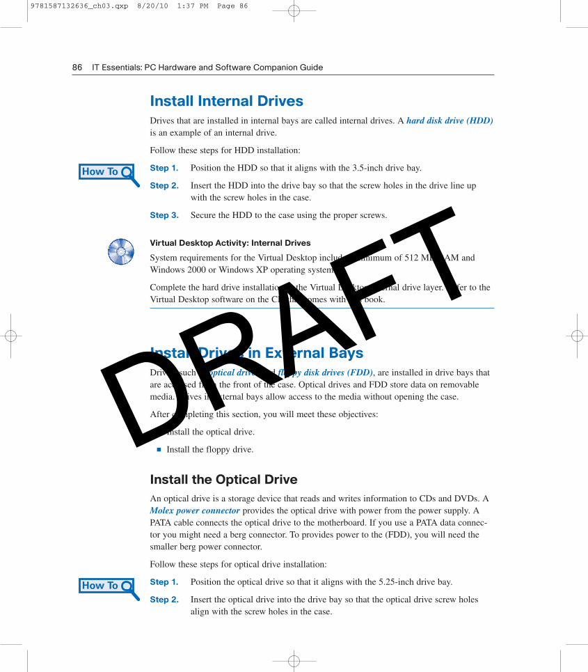
Install Internal DrivesDrives that are installed in internal bays are called internal drives. A hard disk drive (HDD)is an example of an internal drive.
Follow these steps for HDD installation:
Step 1. Position the HDD so that it aligns with the 3.5-inch drive bay.
Step 2. Insert the HDD into the drive bay so that the screw holes in the drive line upwith the screw holes in the case.
Step 3. Secure the HDD to the case using the proper screws.
Virtual Desktop Activity: Internal Drives
System requirements for the Virtual Desktop include a minimum of 512 MB RAM andWindows 2000 or Windows XP operating system.
Complete the hard drive installation in the Virtual Desktop internal drive layer. Refer to theVirtual Desktop software on the CD that comes with this book.
Install Drives in External BaysDrives, such as optical drives and floppy disk drives (FDD), are installed in drive bays thatare accessed from the front of the case. Optical drives and FDD store data on removablemedia. Drives in external bays allow access to the media without opening the case.
After completing this section, you will meet these objectives:
n Install the optical drive.
n Install the floppy drive.
Install the Optical DriveAn optical drive is a storage device that reads and writes information to CDs and DVDs. AMolex power connector provides the optical drive with power from the power supply. APATA cable connects the optical drive to the motherboard. If you use a PATA data connec-tor you might need a berg connector. To provides power to the (FDD), you will need thesmaller berg power connector.
Follow these steps for optical drive installation:
Step 1. Position the optical drive so that it aligns with the 5.25-inch drive bay.
Step 2. Insert the optical drive into the drive bay so that the optical drive screw holesalign with the screw holes in the case.
86 IT Essentials: PC Hardware and Software Companion Guide
How To
How To
9781587132636_ch03.qxp 8/20/10 1:37 PM Page 86
DRAFT
Step 3. Secure the optical drive to the case using the proper screws.
CautionIf you use screws that are too long, you may damage the drive you are mounting.
Install the Floppy DriveA floppy disk drive (FDD) is a storage device that reads and writes information to a floppydisk. A Berg power connector provides the FDD with power from the power supply. Afloppy drive data cable connects the FDD to the motherboard.
A floppy disk drive fits into the 3.5-inch bay on the front of the computer case, as shown inFigure 3-5.
Follow these steps for FDD installation:
Step 1. Position the FDD so that it aligns with the 3.5-inch drive bay.
Step 2. Insert the FDD into the drive bay so that the FDD screw holes align with thescrew holes in the case.
Step 3. Secure the FDD to the case using the proper screws.
Figure 3-5 Floppy Disk Drive Installed
Chapter 3: Computer Assembly—Step by Step 87
How To
Virtual Desktop Activity: Drives in External Bays
System requirements for the Virtual Desktop include a minimum of 512 MB RAM andWindows 2000 or Windows XP operating system.
Complete the optical and floppy drive installation in the Virtual Desktop drives in the exter-nal bays layer. Refer to the Virtual Desktop software on the CD that comes with this book.
9781587132636_ch03.qxp 8/20/10 1:37 PM Page 87
DRAFT
Lab 3.5.2: Install the Drives
In this lab, you install the hard drive, optical drive, and floppy drive. Refer to the lab in ITEssentials: PC Hardware and Software Lab Manual, Fourth Edition. You may perform thislab now or wait until the end of the chapter.
Install Adapter CardsAdapter cards are installed to add functionality to a computer. Adapter cards must be com-patible with the expansion slot. This section focuses on the installation of three types ofadapter cards:
n PCIe x1 NIC
n PCI wireless NIC
n PCIe x16 video adapter card
After completing this section, you will meet these objectives:
n Install the NIC.
n Install the wireless NIC.
n Install the video adapter card.
Install the NICA network interface card (NIC) enables a computer to connect to a network. NICs useperipheral component interface (PCI) and PCIe expansion slots on the motherboard, asshown in Figure 3-6.
Figure 3-6 PCIe Network Interface Card
88 IT Essentials: PC Hardware and Software Companion Guide
9781587132636_ch03.qxp 8/20/10 1:37 PM Page 88
DRAFT
Follow these steps for NIC installation:
Step 1. Remove the blank from the case where the new card will be installed so that theport can be accessed.
Step 2. Align the NIC with the appropriate expansion slot on the motherboard.
Step 3. Press down gently on the NIC until the card is fully seated.
Step 4. Secure the NIC PC mounting bracket to the case with the appropriate screw.
Install the Wireless NICA wireless NIC, as shown in Figure 3-7, enables a computer to connect to a wireless net-work. Wireless NICs use PCI and PCIe expansion slots on the motherboard. Some wirelessNICs are installed externally with a USB connector.
Follow these steps for wireless NIC installation:
Step 1. Align the wireless NIC with the appropriate expansion slot on the motherboard.
Step 2. Press down gently on the wireless NIC until the card is fully seated.
Step 3. Secure the wireless NIC PC mounting bracket to the case with the appropriatescrew.
Figure 3-7 Wireless NIC
Chapter 3: Computer Assembly—Step by Step 89
How To
How To
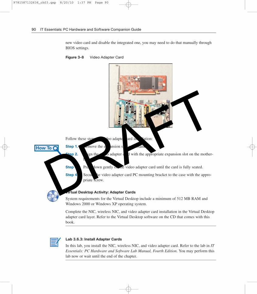
Install the Video Adapter CardA video adapter card, as shown in Figure 3-8, is the interface between a computer and adisplay monitor. An upgraded video adapter card can provide better graphic capabilities forgames and graphic programs. Video adapter cards use PCI, advance graphics port (AGP),and PCIe expansion slots on the motherboard. If the BIOS does not automatically sense the
9781587132636_ch03.qxp 8/20/10 1:37 PM Page 89
DRAFT
new video card and disable the integrated one, you may need to do that manually throughBIOS settings.
Figure 3-8 Video Adapter Card
90 IT Essentials: PC Hardware and Software Companion Guide
Follow these steps for video adapter card installation:
Step 1. Remove the expansion slot case blank.
Step 2. Align the video adapter card with the appropriate expansion slot on the mother-board.
Step 3. Press down gently on the video adapter card until the card is fully seated.
Step 4. Secure the video adapter card PC mounting bracket to the case with the appro-priate screw.
Virtual Desktop Activity: Adapter Cards
System requirements for the Virtual Desktop include a minimum of 512 MB RAM andWindows 2000 or Windows XP operating system.
Complete the NIC, wireless NIC, and video adapter card installation in the Virtual Desktopadapter card layer. Refer to the Virtual Desktop software on the CD that comes with thisbook.
Lab 3.6.3: Install Adapter Cards
In this lab, you install the NIC, wireless NIC, and video adapter card. Refer to the lab in ITEssentials: PC Hardware and Software Lab Manual, Fourth Edition. You may perform thislab now or wait until the end of the chapter.
How To
9781587132636_ch03.qxp 8/20/10 1:37 PM Page 90
DRAFT
Connect All Internal CablesPower cables are used to distribute electricity from the power supply to the motherboardand other components. Data cables transmit data between the motherboard and storagedevices, such as hard drives. Additional cables connect the buttons and link lights on thefront of the computer case to the motherboard.
After completing this section, you will meet these objectives:
n Connect the power cables.
n Connect the data cables.
Connect the Power CablesPower cables are brightly colored bundles of wires that branch out from the power supply.As the name suggests, they provide internal devices with electricity. There are several kindsof power connectors.
Motherboard Power ConnectionsJust like other components, motherboards require power to operate. The AdvancedTechnology Extended (ATX) main power connector will have either 20 or 24 pins. Thepower supply may also have a 4-pin or 6-pin Auxiliary (AUX) power connector that con-nects to the motherboard. A 20-pin connector will work in a motherboard with a 24-pinsocket.
Follow these steps for motherboard power cable installation:
Step 1. Align the 20-pin ATX power connector with the socket on the motherboard.
Step 2. Gently press down on the connector until the clip clicks into place.
Step 3. Align the 4-pin AUX power connector with the socket on the motherboard.
Step 4. Gently press down on the connector until the clip clicks into place.
SATA Power ConnectorsSATA power connectors use a 15-pin connector. Serial advanced technology attachment(SATA) power connectors are used to connect to hard disk drives, optical drives, or anydevices that have a SATA power socket.
Molex Power ConnectorsHard disk drives and optical drives that do not have SATA power sockets use a Molexpower connector.
Chapter 3: Computer Assembly—Step by Step 91
How To
9781587132636_ch03.qxp 8/20/10 1:37 PM Page 91
DRAFT
CautionDo not use a Molex connector and a SATA power connector on the same drive at the same time. Itwill prevent the drive from working properly.
Berg Power ConnectorsThe 4-pin Berg power connector supplies power to a floppy drive.
Follow these steps for Berg power connector installation:
Step 1. Plug the SATA power connector into the HDD.
Step 2. Plug the Molex power connector into the optical drive.
Step 3. Plug the 4-pin Berg power connector into the FDD.
Step 4. Connect the 3-pin fan power connector into the appropriate fan header on themotherboard, according to the motherboard manual.
Step 5. Plug the additional cables from the case into the appropriate connectors accord-ing to the motherboard manual.
Connect the Data CablesDrives connect to the motherboard using data cables. The drive being connected determinesthe type of data cable used. The types of data cables are PATA, SATA, and floppy disk.
PATA Data CablesThe parallel advanced technology attachment (PATA) data cable is sometimes called a rib-bon cable because it is wide and flat. The PATA cable can have either 40 or 80 conductors.A PATA cable usually has three 40-pin connectors. One connector at the end of the cableconnects to the motherboard. The other two connectors connect to drives. If multiple harddrives are installed, the master drive connects to the end connector. The slave drive connectsto the middle connector.
A stripe on the data cable denotes the location of Pin 1. Plug the PATA cable into the drivewith the Pin 1 indicator on the cable aligned with the Pin 1 indicator on the drive connector.The Pin 1 indicator on the drive connector is usually closest to the power connector on thedrive. Many motherboards have two PATA drive controllers, providing support for a maxi-mum of four PATA drives.
SATA Data CablesThe SATA data cable has a 7-pin connector. One end of the cable is connected to the moth-erboard. The other end is connected to any drive that has a SATA data connector.
92 IT Essentials: PC Hardware and Software Companion Guide
How To
9781587132636_ch03.qxp 8/20/10 1:37 PM Page 92
DRAFT
Reattach the Side Panels and Connect ExternalCables to the ComputerNow that all the internal components have been installed and connected to the motherboardand power supply, you need to reattach the side panels to the computer case. The next stepis to connect the cables for all computer peripherals and the power cable.
After completing this section, you will meet these objectives:
n Reattach the side panels to the case.
n Connect external cables to the computer.
Reattach the Side Panels to the CaseMost computer cases have two panels, one on each side. Some computer cases have onethree-sided cover that slides down over the case frame.
When the cover is in place, make sure that it is secured at all screw locations. Some com-puter cases use screws that are inserted with a screwdriver. Other cases have knob-typescrews that can be tightened by hand. Tool-less cases simply “click” closed.
If you are unsure about how to remove or replace the computer case, refer to the documen-tation or website of the manufacturer for more information.
CautionHandle case parts with care. Some computer case covers have sharp or jagged edges.
Connect External Cables to the ComputerAfter the case panels have been reattached, connect the cables to the back of the computer.Here are some common external cable connections:
n Monitor
n Keyboard
n Mouse
n USB
n Ethernet
n Power
When attaching cables, ensure that they are connected to the correct locations on the com-puter. For example, some mouse and keyboard cables use the same type of PS/2 connector.
Chapter 3: Computer Assembly—Step by Step 93
9781587132636_ch03.qxp 8/20/10 1:37 PM Page 93
DRAFT
Floppy Drive Data CablesThe floppy drive data cable has a 34-pin connector. Like the PATA data cable, the floppydrive data cable has a stripe to denote the location of Pin 1. A floppy drive cable usuallyhas three 34-pin connectors. One connector at the end of the cable connects to the mother-board. The other two connectors connect to drives. If multiple floppy drives are installed,the A: drive connects to the end connector. The B: drive connects to the middle connector.
Plug the floppy drive data cable into the drive with the Pin 1 indicator on the cable alignedwith the Pin 1 indicator on the drive connector. Motherboards have one floppy drive con-troller, providing support for a maximum of two floppy drives.
NoteIf Pin 1 on the floppy drive data cable is not aligned with Pin 1 on the drive connector, the floppydrive does not function. This misalignment does not damage the drive, but the drive activity light dis-plays continuously. To fix this problem, turn off the computer and reconnect the data cable so thatPin 1 on the cable and Pin 1 on the connector are aligned. Reboot the computer.
Follow these steps for data cable installation:
Step 1. Plug the motherboard end of the PATA cable into the motherboard socket.
Step 2. Plug the connector at the far end of the PATA cable into the optical drive.
Step 3. Plug one end of the SATA cable into the motherboard socket.
Step 4. Plug the other end of the SATA cable into the HDD.
Step 5. Plug the motherboard end of the FDD cable into the motherboard socket.
Step 6. Plug the connector at the far end of the FDD cable into the floppy drive.
Step 7. Double check to make sure all cables are securely connected to the devices andto the motherboard.
Virtual Desktop Activity: Internal Cables
System requirements for the Virtual Desktop include a minimum of 512 MB RAM andWindows 2000 or Windows XP operating system.
Complete the internal cable installation in the Virtual Desktop internal cable layer. Refer tothe Virtual Desktop software on the CD that comes with this book.
Lab 3.7.2: Install Internal Cables
In this lab, you install internal power and data cables in the computer. Refer to the lab in ITEssentials: PC Hardware and Software Lab Manual, Fourth Edition. You may perform thislab now or wait until the end of the chapter.
94 IT Essentials: PC Hardware and Software Companion Guide
How To
9781587132636_ch03.qxp 8/20/10 1:37 PM Page 94
DRAFT
CautionWhen attaching cables, never force a connection.
NotePlug in the power cable after you have connected all other cables.
Follow these steps for external cable installation:
Step 1. Attach the monitor cable to the video port.
Step 2. Secure the cable by tightening the screws on the connector.
Step 3. Plug the keyboard cable into the PS/2 keyboard port.
Step 4. Plug the mouse cable into the PS/2 mouse port.
Step 5. Plug the USB cable into a USB port.
Step 6. Plug the network cable into the network port.
Step 7. Connect the wireless antenna to the antenna connector.
Step 8. Plug the power cable into the power supply.
Figure 3-9 shows all of the external cables plugged into the back of the computer.
Figure 3-9 All External Cables Plugged into the Back
Chapter 3: Computer Assembly—Step by Step 95
How To
Virtual Desktop Activity: External Cables
System requirements for the Virtual Desktop include a minimum of 512 MB RAM andWindows 2000 or Windows XP operating system.
Complete the external cable installation in the Virtual Desktop external cable layer. Refer tothe Virtual Desktop software on the CD that comes with this book.
9781587132636_ch03.qxp 8/20/10 1:37 PM Page 95
DRAFT
Lab 3.8.2: Complete the Computer Assembly
In this lab, you reattach the case and connect the external cables to complete the computerassembly. Refer to the lab in IT Essentials: PC Hardware and Software Lab Manual, FourthEdition. You may perform this lab now or wait until the end of the chapter.
Boot the Computer for the First TimeWhen the computer is booted, the basic input/output system (BIOS) performs a check onall of the internal components, as shown in Figure 3-10. This check is called a power-onself test (POST).
After completing this section, you will meet these objectives:
n Identify beep codes.
n Describe BIOS setup.
Figure 3-10 BIOS Setup Screenshot
96 IT Essentials: PC Hardware and Software Companion Guide
Identify Beep CodesPOST checks to see that all of the hardware in the computer is operating correctly. If adevice is malfunctioning, an error or a beep code alerts the technician that there is a prob-lem. Typically, a single beep denotes that the computer is functioning properly. If there is a
9781587132636_ch03.qxp 8/20/10 1:37 PM Page 96
DRAFT
hardware problem, the computer might emit a series of beeps. Each BIOS manufactureruses different codes to indicate hardware problems. Table 3-1 shows a sample chart of beepcodes. The beep codes for your computer might be different. Consult the motherboard doc-umentation to view beep codes for your computer.
Table 3-1 Sample Beep Codes
Beep Code Meaning Cause
1 beep Passed POST Successfully passed POST
2 beeps Memory parity error Bad memory
3 beeps Base 64K memory failure Bad memory
4 beeps Timer not operational Bad motherboard
5 beeps Processor error Bad processor
6 beeps 8042 gate A20 failure Bad CPU or motherboard
7 beeps Processor exception Bad processor
8 beeps Video memory error Bad video card or memory
9 beeps ROM checksum error Bad BIOS
10 beeps CMOS checksum error Bad motherboard
11 beeps Cache memory bad Bad CPU or motherboard
Describe BIOS SetupThe BIOS contains a setup program used to configure settings for hardware devices. Theconfiguration data is saved to a special memory chip called a complementary metal-oxidesemiconductor (CMOS). CMOS is maintained by the battery in the computer. If this batterydies, all BIOS setup configuration data will be lost. If this occurs, replace the battery andreconfigure the BIOS settings.
To enter the BIOS setup program, you must press the proper key or key sequence duringPOST. Most computers use the Delete key. Your computer might use another key or combi-nation of keys.
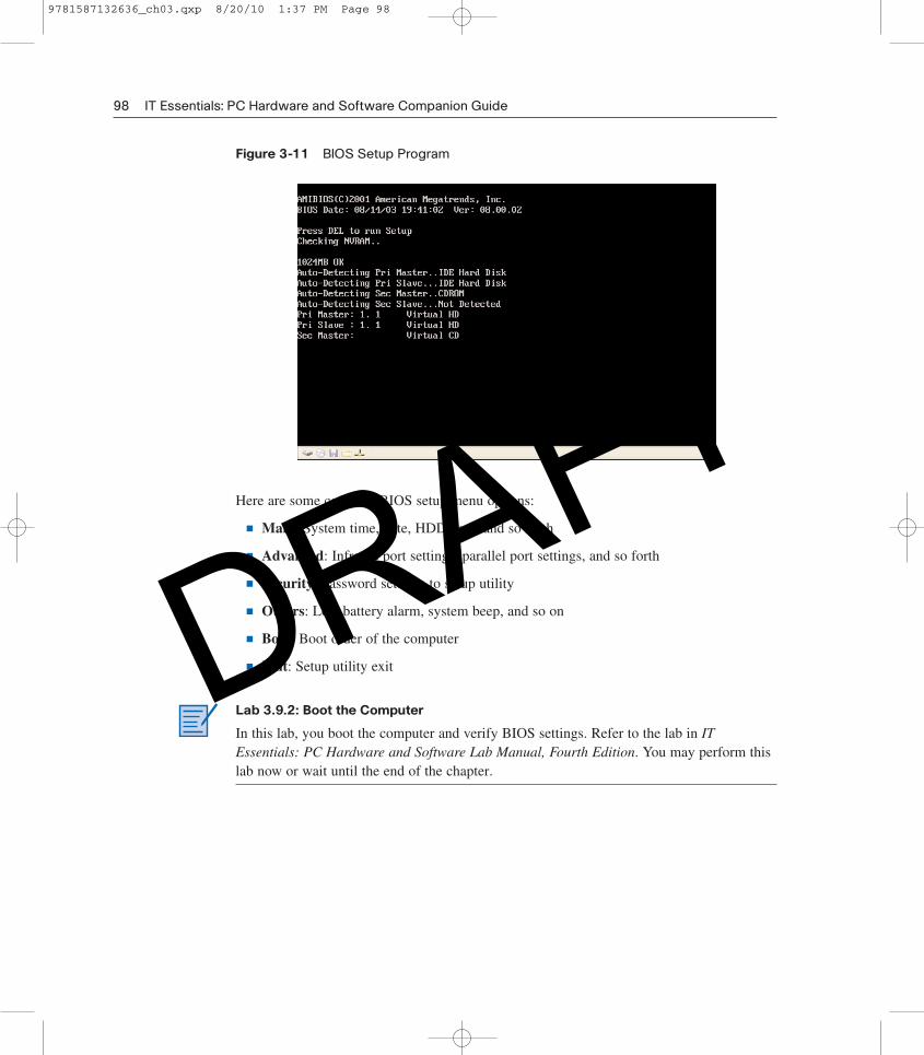
Figure 3-11 shows an example of a BIOS setup program.
Chapter 3: Computer Assembly—Step by Step 97
9781587132636_ch03.qxp 8/20/10 1:37 PM Page 97
DRAFT
Here are some common BIOS setup menu options:
n Main: System time, date, HDD type, and so forth
n Advanced: Infrared port settings, parallel port settings, and so forth
n Security: Password settings to setup utility
n Others: Low battery alarm, system beep, and so on
n Boot: Boot order of the computer
n Exit: Setup utility exit
Lab 3.9.2: Boot the Computer
In this lab, you boot the computer and verify BIOS settings. Refer to the lab in ITEssentials: PC Hardware and Software Lab Manual, Fourth Edition. You may perform thislab now or wait until the end of the chapter.
98 IT Essentials: PC Hardware and Software Companion Guide
Figure 3-11 BIOS Setup Program
9781587132636_ch03.qxp 8/20/10 1:37 PM Page 98
DRAFT
Chapter 3: Computer Assembly—Step by Step 99
SummaryThis chapter detailed the steps used to assemble a computer and boot the system for the firsttime. These are some important points to remember:
n Computer cases come in a variety of sizes and configurations. Many of the computer’scomponents must match the case’s form factor.
n The CPU is installed on the motherboard with a heat sink/fan assembly.
n The power supply is installed in the PC.
n RAM is installed in RAM slots found on the motherboard.
n Adapter cards are installed in PCI and PCIe expansion slots found on the motherboard.
n Hard disk drives are installed in 3.5-inch drive bays located inside the case.
n Optical drives are installed in 5.25-inch drive bays that can be accessed from outsidethe case.
n Floppy drives are installed in 3.5-inch drive bays that can be accessed from outside thecase.
n Power supply cables are connected to all drives and the motherboard.
n Internal data cables transfer data to all drives.
n External cables connect peripheral devices to the computer.
n Beep codes signify when hardware malfunctions.
n The BIOS setup program is used to display information about the computer compo-nents and allows the user to change system settings.
Summary of ExercisesThis is a summary of the Labs, Worksheets, Remote Technician exercises, ClassDiscussions, Virtual Desktop activities, and Virtual Laptop activities associated with thischapter.
LabsThe following labs cover material from this chapter. Refer to the labs in IT Essentials: PCHardware and Software Lab Manual, Fourth Edition.
Lab 3.2.0: Install the Power Supply
Lab 3.3.3: Install the Motherboard
Lab 3.5.2: Install the Drives
9781587132636_ch03.qxp 8/20/10 1:37 PM Page 99
DRAFT
100 IT Essentials: PC Hardware and Software Companion Guide
Lab 3.6.3: Install Adapter Cards
Lab 3.7.2: Install Internal Cables
Lab 3.8.2: Complete the Computer Assembly
Lab 3.9.2: Boot the Computer
Virtual Desktop ActivitiesThe following Virtual Desktop activities cover material from this chapter. Refer to theVirtual Desktop software on the CD that comes with this book.
Virtual Desktop Activity: Power Supply
Virtual Desktop Activity: Motherboard
Virtual Desktop Activity: Internal Drives
Virtual Desktop Activity: Drives in External Bays
Virtual Desktop Activity: Adapter Cards
Virtual Desktop Activity: Internal Cables
Virtual Desktop Activity: External Cables
Check Your UnderstandingYou can find the answers to these questions in the appendix, “Answers to Check YourUnderstanding Questions.”
1. A technician is installing a new power supply in a computer. Which type of power con-nector should be used to connect to a CD-ROM?
A. Berg
B. Mini-Molex
C. Molex
D. 20-pin ATX connector
2. A technician is installing a new power supply in a computer. Which type of power con-nector should be used to connect to an ATX motherboard?
A. Berg
B. Mini-Molex
C. Molex
D. 20-pin connector
9781587132636_ch03.qxp 8/20/10 1:37 PM Page 100
DRAFT
Chapter 3: Computer Assembly—Step by Step 101
3. When a technician installs a new CPU, what will help maintain even contact and heatdistribution between the CPU and heat sink?
A. Silicon spray
B. Graphite paste
C. Glue
D. Thermal compound
4. When installing a CPU in a ZIF socket, how should the technician align the pins toavoid damage?
A. Pin 1 is always aligned with the corner opposite the base of the lever.
B. Pin 1 on the CPU is aligned with Pin 1 on the ZIF socket.
C. Pin 1 is aligned with the corner closest to the memory.
D. The removed corner of the CPU is always aligned with the corner opposite Pin 1.
5. A technician is installing additional memory in a computer. How can the technicianguarantee that the memory is correctly aligned?
A. The label on the memory module should always face the CPU.
B. A notch in the memory module should be aligned with a notch in the slot on themotherboard.
C. The arrows on the memory module should be aligned with the arrows on the moth-erboard slot.
D. All memory and motherboard slots are color-coded, with one red end and one blueend.
6. When mounting a motherboard in a computer case, what does the technician use toprevent the motherboard from touching the bottom of the case?
A. Standoffs
B. Ground-fault isolators
C. Silicon spray
D. Grounding straps
7. When installing adapter cards in a computer, how should a technician properly securethe card?
A. Install the card, and attach it to the expansion slot using thermal paste.
B. Install the card, and attach it to the motherboard using thermal pads.
C. Install the card, and secure it using metal retaining clips located on the expansionslot.
D. Install the card, and secure it to the case with a screw. Or, if the case provides plas-tic or metal clips, use them.
9781587132636_ch03.qxp 8/20/10 1:37 PM Page 101
DRAFT
102 IT Essentials: PC Hardware and Software Companion Guide
8. Which two connectors are used to connect external peripherals?