38


Modulations
Analog Modulations • Amplitude modulation (AM)
– Linear modulation • Frequency modulation (FM) • Phase modulation (PM)
cos
• Angle modulation
– FM – PM
Digital Modulations • ASK • FSK • PSK • MSK • MFSK • QAM • PAM • Etc.

AM Modulators/Demodulators
AM Modulators • Multiplication modulator • Non‐linear modulator • Switching modulator
– Ring modulator
AM Demodulators • Coherent demodulator • Rectifier • Envelope Detector
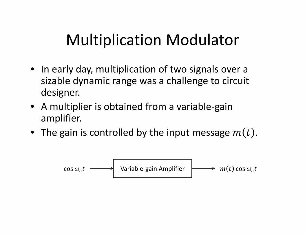
Multiplication Modulator
• In early day, multiplication of two signals over a sizable dynamic range was a challenge to circuit designer.
• A multiplier is obtained from a variable‐gain amplifier.
• The gain is controlled by the input message .
Variable‐gain Amplifier cos cos

Nonlinear DSB‐SC Modulator
• Add input message and carrier, then perform non‐linear operation• cos • cos • • • 2 ∙ 4 ∙ cos
Spring 2012

Switching Modulation

Switching Modulation
• Any periodic signal can be expressed by a trigonometric Fourier Series.
cos
12
2 12 1 cos 2 1
12
2cos
13 cos 3
15 cos 5 ⋯
Outputofbandpassfilter2
cos

Switching Modulator
(a) Diode‐bridge electronic switch. (b) Series‐bridge diode modulator. (c) Shunt‐bridge diode modulator.
During positive half of cycle, • All the diodes conduct • a and b are shorted During negative half of cycle, • All the diodes open. • a and b are opened.
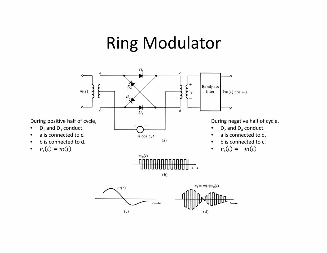
Ring Modulator
Spring 2012
During negative half of cycle, • D2 and D4 conduct. • a is connected to d. • b is connected to c. •
During positive half of cycle, • D1 and D3 conduct. • a is connected to c. • b is connected to d. •

Ring Modulation
• Any periodic signal can be expressed by a trigonometric Fourier Series.
cos
4 1
2 1 cos 2 1
4
cos13 cos 3
15 cos 5 ⋯
Outputofbandpassfilter4
cos

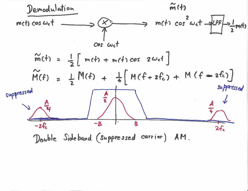
Demodulation of DSB‐SC Signals • The receiver must generate a carrier that synchronous in
phase and in frequency with the incoming carrier. (coherent demodulator)
cos
• Not easy in practice
– Delay – Doppler effect ∆
cos ∆ cos ∆
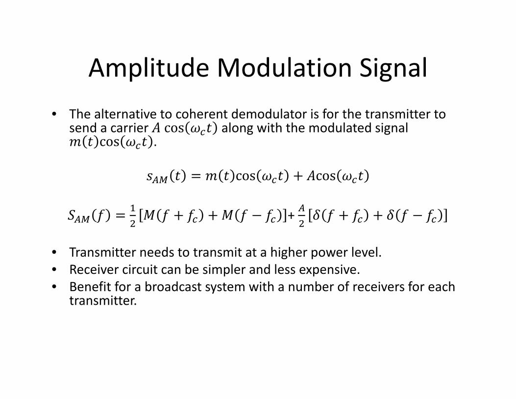
Amplitude Modulation Signal • The alternative to coherent demodulator is for the transmitter to
send a carrier cos along with the modulated signal cos .
cos cos
+
• Transmitter needs to transmit at a higher power level. • Receiver circuit can be simpler and less expensive. • Benefit for a broadcast system with a number of receivers for each
transmitter.

AM Signal and Its Envelope

Envelope Detection • Envelope detection condition
1. ≫ bandwidthof 2. 0
• Modulation index For envelope to be distortionless, 0 1
• with zero offset – Let be the maximum and minimum of .
min
• with non‐zero offset (rare case), min max
max min2 max min

Modulation Index
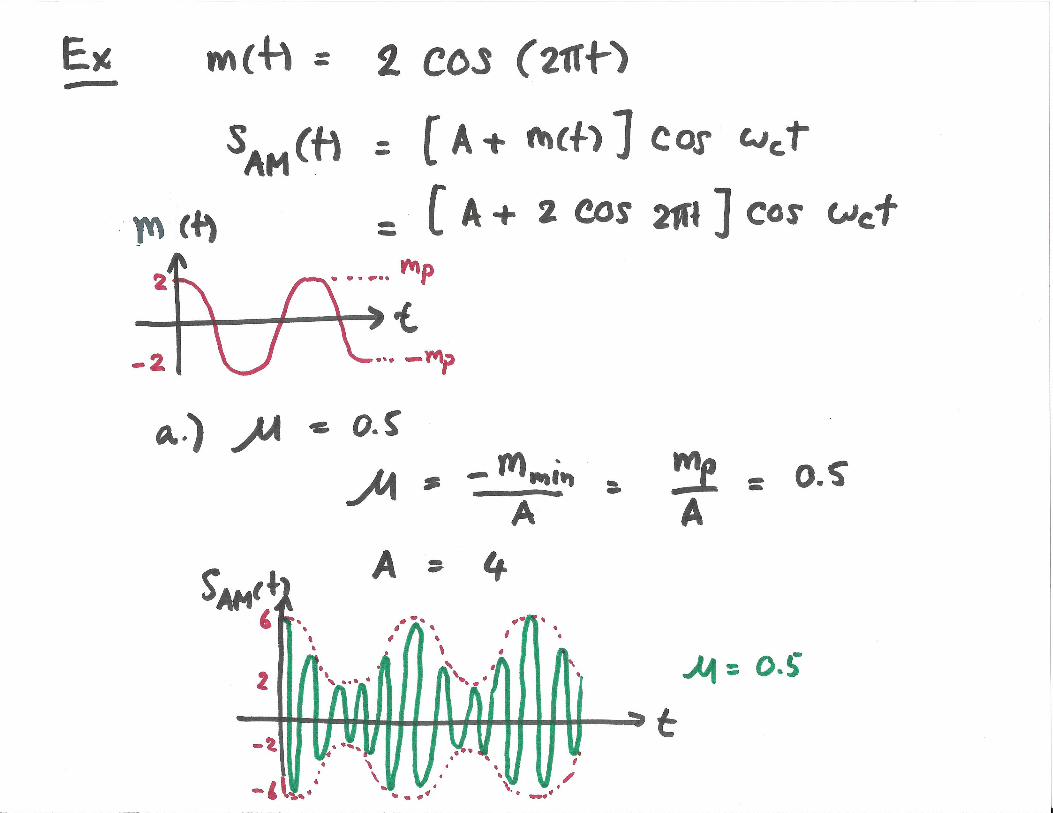
• Tone modulation, cos
• For modulation indices ( ) of 0.5 and 1. cos
cos 1 cos cos
(a) 50% modulation. (b) 100% modulation.

Sideband and Carrier Power cos cos
• Carrier power
• Sideband power • Power efficiency
usefulpowertotalpower 100%
• For tone modulation,
2
2 100%
• In case of 50% modulation, 11.11%

Rectifier Detector for AM

Envelope Detector for AM
Spring 2012
For proper operation, the discharge time constant RC must be chosen properly.
1≪
12
Discharge rate
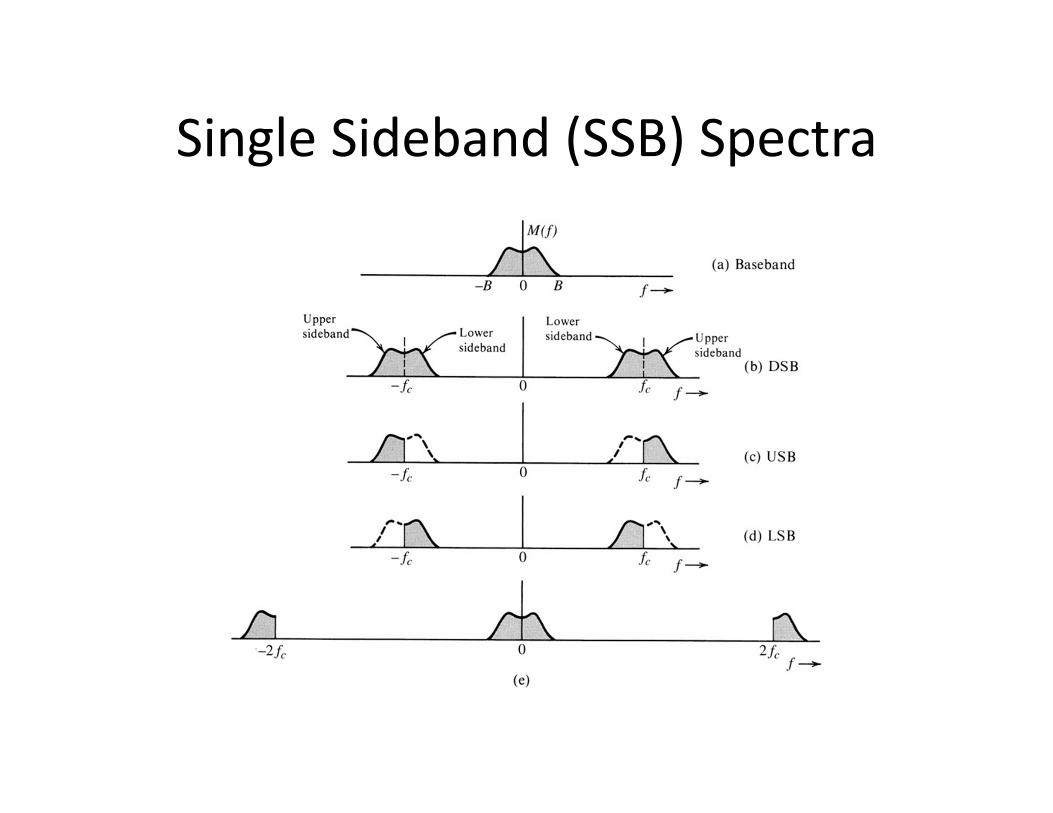
Single Sideband (SSB) Spectra
Spring 2012

SSB Spectra for Tone Modulation

SSB Modulation
• Conceptually, the generation of a SSB signal is straightforward. – Generate a DSB signal. – Apply an ideal band‐pass filter.
• Practically, the construction of ideal filter is very difficult.
• Similar to a DSB signal, coherent demodulation is required to detect an SSB signal.

Quadrature Amplitude Modulation (QAM)
• Because SSB‐SC signals are difficult to generate accurately, QAM offer an alternative to SSB‐SC. – QAM can be generated without requiring sharp cutoff band‐pass filters.
• Two baseband signals, and , each of bandwidth Hz, can be transmitted simultaneously over a bandwidth by using DSB transmission and quadrature multiplexing. – Upper channel = in‐phase (I) channel – Lower channel = quadrature (Q) channel

Quadrature Amplitude Modulation (QAM)
cos sin
cos 2 sin 2 cos 2 sin 2

Quadrature Amplitude Modulation (QAM)
• QAM demodulation must be synchronous. An error in phase or frequency of the carrier at the demodulator will result in loss and interference between the two channels.
• If the carrier at the demodulator is , the output of the upper receiver branch will become
• This is called co‐channel interference.


![GTTI08 Fotonica Avanex.ppt [modalità compatibilità] drivers, is reduced by decreasing the modulator driving voltage 5 Optically chirped modulators Ground electrode Hot electrode](https://static.documents.pub/doc/80x56/5ae225f07f8b9a495c8bb1a6/gtti08-fotonica-modalit-compatibilit-drivers-is-reduced-by-decreasing-the-modulator.jpg)


![A 130 GHz Electro-Optic Ring Modulator with Double-Layer ......the ring resonator modulators with graphene on top of them [21 23]. These kinds of electro-optic modulators have both](https://static.documents.pub/doc/80x56/60a6d2dc89cc8055dc7fd0f9/a-130-ghz-electro-optic-ring-modulator-with-double-layer-the-ring-resonator.jpg)


