1 Chapter 4 Anaerobic Sewage Treatment using UASB Reactors: Engineering and Operational Aspects Jules B. van Lier 1 , Anand Vashi 2 , Jeroen van der Lubbe 3 and Barry Heffernan 3 1 Faculty of Civil Engineering and Geosciences, Department of Water Management, Delft University of Technology, The Netherlands 2 Enviro Control Associates (I) PVT.LTD. Opp. Bank of Mahashtra, Ghod Dod Road, Surat- 395 001, Gujarat, India 3 Biothane Systems International, Tanthofdreef 21, 2600 GB Delft, The Netherland. [email protected]Anaerobic pre-treatment of domestic sewage using UASB reactor systems offers a number of advantages, e.g. system compactness, negligible or no energy consumption, stabilised excess sludge production, potential for energy recovery, low-cost accessibility of sewage for agricultural reuse purposes, etc.. Research on high-rate anaerobic sewage treatment started in the early 1980s with the 64 m 3 UASB pilot plant in Cali, Colombia and various other initiatives in Brazil. Hereafter the technology was adapted to full-scale conditions and slowly introduced in the market. This chapter describes the anaerobic treatment process for domestic sewage and evaluates the performance of current large scale reactor systems located in (sub-) tropical areas. Although the perspectives from the early 1980s were confirmed in bench-scale studies, a considerable number of the recently constructed treatment plants deliver disappointing performance results. In many cases, inadequate designs, improper reactor operation and insufficient control are responsible for these poor performances. A brief survey is made on the preconditions that must be met prior to starting and operating sewage treatment plants based on the UASB concept. Adequate maintenance and basic system knowledge at the level of plant manager seems to be indispensible for a full scale success. 1. INTRODUCTION Since the mid 1990s, approximately 10 years after the installation of the first pilot scale upflow anaerobic sludge bed (UASB) reactors for the treatment of municipal sewage in Cali Colombia (Lettinga et al. 1993; Schellinkhout et al. 1985) and Brazil (Vieira and Souza 1986), there has been a rapid increase in the number of large scale municipal UASB sewage treatment plants (STPs) installed in sub-tropical countries. In particular, Brazil and India have extensively adopted the UASB technology. For example, the authors were able to identify over 45 municipal UASB STPs in India with an average daily flow rate of 10,000 m 3 or more (the largest STP was designed for a flow rate of 338,000 m 3 ·d -1 ) while 15 such STPs were identified in Brazil. The main benefits associated with UASB based STPs compared to conventional aerobic treatment are a significant reduction in energy consumption and the potential for energy self sufficiency. Constraints include potential odour problems and
Transcript
1
Chapter 4
Anaerobic Sewage Treatment using UASB Reactors: Engineering and Operational Aspects
Jules B. van Lier1, Anand Vashi2, Jeroen van der Lubbe3 and Barry Heffernan3 1 Faculty of Civil Engineering and Geosciences, Department of Water Management,
Delft University of Technology, The Netherlands 2 Enviro Control Associates (I) PVT.LTD. Opp. Bank of Mahashtra, Ghod Dod Road, Surat-
395 001, Gujarat, India 3 Biothane Systems International, Tanthofdreef 21, 2600 GB Delft, The Netherland.
Anaerobic pre-treatment of domestic sewage using UASB reactor systems offers a number of advantages, e.g. system compactness, negligible or no energy consumption, stabilised excess sludge production, potential for energy recovery, low-cost accessibility of sewage for agricultural reuse purposes, etc.. Research on high-rate anaerobic sewage treatment started in the early 1980s with the 64 m3 UASB pilot plant in Cali, Colombia and various other initiatives in Brazil. Hereafter the technology was adapted to full-scale conditions and slowly introduced in the market. This chapter describes the anaerobic treatment process for domestic sewage and evaluates the performance of current large scale reactor systems located in (sub-) tropical areas. Although the perspectives from the early 1980s were confirmed in bench-scale studies, a considerable number of the recently constructed treatment plants deliver disappointing performance results. In many cases, inadequate designs, improper reactor operation and insufficient control are responsible for these poor performances. A brief survey is made on the preconditions that must be met prior to starting and operating sewage treatment plants based on the UASB concept. Adequate maintenance and basic system knowledge at the level of plant manager seems to be indispensible for a full scale success.
1. INTRODUCTION
Since the mid 1990s, approximately 10 years after the installation of the first pilot scale upflow anaerobic sludge bed (UASB) reactors for the treatment of municipal sewage in Cali Colombia (Lettinga et al. 1993; Schellinkhout et al. 1985) and Brazil (Vieira and Souza 1986), there has been a rapid increase in the number of large scale municipal UASB sewage treatment plants (STPs) installed in sub-tropical countries. In particular, Brazil and India have extensively adopted the UASB technology. For example, the authors were able to identify over 45 municipal UASB STPs in India with an average daily flow rate of 10,000 m3 or more (the largest STP was designed for a flow rate of 338,000 m3·d-1) while 15 such STPs were identified in Brazil. The main benefits associated with UASB based STPs compared to conventional aerobic treatment are a significant reduction in energy consumption and the potential for energy self sufficiency. Constraints include potential odour problems and
2
difficulties associated with, including nutrient removal in the treatment scheme. Table 4.1 lists the most important benefits and constraints associated with the implementation of anaerobic sewage treatment.
The rapid uptake of the municipal UASB technology was stimulated by the excellent performance of the Cali pilot plant and some other early municipal UASB plants such as Pedregal, Bucaramanga and Kanpur (van Haandel and Lettinga 1994; Schellinkhout and Collazos 1992; Schellinkhout and Osorio 1994; Draaijer et al. 1992 and 1994). The obtained maximum removal efficiencies for COD, BOD and SS reached 70-80%, 75-85%, and 70-80%, respectively. Table 4.2 lists average values from the early plants obtained in Colombia, Brazil and India.
The mentioned reduction in investment costs (Table 4.1) is attributed to the omission of electro-mechanical units, such as aerators, as well as the reduced need for volumetric unit capacity, owing to the so-called ‘shared functionality’ of the anaerobic treatment tank. In fact, a UASB reactor comprises 4 functional units (Fig. 4.1):
1) Primary clarifier: removal/entrapment of (non)biodegradable suspended solids from the influent.
2) Biological reactors (secondary treatment): Removal of biodegradable organic compounds by converting them into methane.
3) Secondary clarifier: clarifying the treated effluent in the settler zone at the top part of the UASB reactor.
4) Sludge digester: stabilisation (digestion) and improving the dewatering characteristics of the retained influent primary sludge.
Obviously, the head-works, i.e. influent pumps if gravity cannot be used, screens, and sand/grit removal chambers are needed for any treatment system. For anaerobic sewage treatment, though, special care must be taken with the pre-treatment units as they determine reactor stability and long-term performance successes. For instance, clogging of influent pipes can be minimised by applying step screens. Several contractors advise fine (mesh or bar) widths not more than 6 mm clear distance. Such step screens should immediately follow from the coarse bar rack screens which generally have openings of 3-8 cm. With a width of 6 mm, screen automation is indispensible. Therefore, the step screen is often the most expensive part of the treatment system.
Notwithstanding the aforementioned excellent treatment results, recent literature reports and our own surveys suggest that the performance of the more recently constructed large scale municipal UASB STPs is inferior to the results reported for the early pilot and full scale plants (Table 4.3). For sake of convenience, Table 4.3 lists averaged values only. Standard deviations, and particularly those referring to the data from India, have a very wide range, even yielding negative removal efficiencies. Very low average removal efficiencies are also obtained with a recently commissioned UASB reactor treating SO4
2- rich sewage in the Gulf Area. Obviously, in the latter case the organic BOD is converted into inorganic BOD (H2S/HS-) leading to extremely disappointing results. Compared to the overall results of the initial installations, the average treatment efficiencies of the more novel systems dropped from 67% to 57% for COD removal, from 78% to 60% for BOD removal and from 63% to 60% for TSS removal.
Flaws in hardware engineering, combined with often underestimated shortcomings in operational and managerial aspects, contribute to the sometimes rather disappointing treatment results, which are particularly observed in India. For instance, very strikingly, half
3
Table 4.1. Main advantages and constraints of high-rate anaerobic sewage treatment systems.
Advantages (compared to aerobic processes)
• Substantial (reaching 90%) savings in operational costs as no energy is required for aeration. • Significant reductions in investment costs as less treatment units are required. • The produced CH4 is of interest for energy recovery or electricity production. • The technologies do not make use of high-tech equipment, except for main headwork pumps
and fine screens. The treatment system is less dependent on imported technologies. • The process is robust and can handle periodic high hydraulic and organic loading rates. • The system is compact with hydraulic retention times (HRTs) of 6-9 h, and is, therefore,
suitable for application in urban areas, minimising conveyance costs. • Small scale applications allow decentralised treatment, making sewage treatment less
dependent on the extent of seweage networks. • The sludge production is low, well stabilized and easily dewatered; consequently, it does not
require extensive post-treatment. • The valuable nutrients (N and P) are conserved which give the treated wastewater a high
potential for crop ferti-irrigation. • A well designed UASB filters effectively Helminth’s eggs from the influent, allowing the
treated effluent for agricultural reuse.
Constraints
• Anaerobic treatment, although converting most of influent COD into CH4, is a partial treatment, requiring adequate post-treatment to meet the discharge or reuse criteria.
• The produced CH4 is partially dissolved in the effluent (depending on the influent COD concentration). So far no measures are applied to prevent CH4 escaping to the atmosphere.
• The collected CH4 is often not utilised for energy generation and in some cases not even flared. • There is little experience with full-scale application at moderate to low temperatures. • Reduced gases, like H2S, that are dissolved in the effluent may escape causing odour problems. • High influent SO4
2- concentrations may limit the applicability of anaerobic sewage treatment as it results in the conversion of organic BOD/COD to inorganic BOD/COD.
Table 4.2. Treatment performance of the first full-scale UASB plants treating municipal sewage. COD refers to total COD of the raw wastewater (van Haandel and Lettinga 1994).
Country Volume (m3)
Temperature (°C)
HRT (h)
CODInf
(mg·l-1) CODeff
$
(mg·l-1) CODrem
(%) Colombia 64 24-26 4-6 267 110 65
Colombia 6,600 25 5.2 380 150 60-80
Brazil 120 23 4.7-9 315-265 145 50-70 Brazil 67.5 23 7 402 130 74 Brazil 810 30 9.7 563 185 67 India 1,200 20-30 6 563 146 74
$ cCalculated from the influent COD and removal efficiency
4
Table 4.3. Performance of the more recently installed full-scale UASB plants treating municipal sewage in different parts of the world. COD refers to total COD of the raw wastewater.
Effluent content Removal efficiency
STP COD
(mg·l-1)
BOD (mg·l-1)
TSS (mg·l-1)
COD (%)
BOD (%)
TSS (%)
India1 364 137 357 43 55 18
India (survey) 285 121 107 46 41 49
Brazil2 251 98 85 65 74 71
Brazil (survey) 247 97 112 62 67 54
Middle East3 221 83 63 71 70 85 1Sato et al. (2006); 2Oliveira and von Sperling (2009); 3Nada et al. (2006)
screensgrit
chamber
Raw sewage
primarysedimentation
tank
activatedsludge
tank
secondarysedimentation
tank
sludgedigestion
sludgedewatering
Sludge
Treated effluent
Activated sludge for sewage treatment
screensgrit
chamber
Raw sewage
screensgrit
chamber
Raw sewage
primarysedimentation
tank
activatedsludge
tank
secondarysedimentation
tank
sludgedigestion
sludgedewatering
sludgedewatering
Sludge
Treated effluent
Activated sludge for sewage treatment
screensgrit
chamber
Raw sewage
high-rate anaerobictreatment
Effluent polishing
Sludge dryingbeds
Sludge
Treated effluent
Anaerobic sewage treatment
screensgrit
chamber
Raw sewage
screensgrit
chamber
Raw sewage
high-rate anaerobictreatment
Effluent polishing
Sludge dryingbeds
Sludge
Treated effluent
Anaerobic sewage treatment
Fig. 4.1. Functional units of an STP, comparing activated sludge (up) and UASB technology (down)
of the monitored UASBs by Sato et al. (2006) had more suspended solids in the effluent of the UASBs compared to the influent values. Since in India, discharge of untreated sewage is the single most important cause for pollution of surface and ground water (CPCB 2007), major attention has been put on the implementation of sewage treatment plants in the passed decades. The programme of pollution abatement of rivers was started by the Ministry of Environment and Forests (MoEF), Government of India, with the launching of the Ganga Action Plan (GAP) Phase-I in June 1985. The UASB technology for sewage treatment was introduced in India under GAP-I in late 1980s. A pilot plant of 5000 m3·d-1 capacity, using UASB technology, followed by a 1-day hydraulic retention time (HRT) polishing pond was
5
constructed for the treatment of combined wastewater, i.e. domestic and tannery waste (Wiegant et al. 1999) and later exclusively for domestic sewage only. The results of these initial reactor systems were in agreement or even better than the expected performance data, although start-up procedures took longer than had been predicted (Draaijer et al. 1994). Later in April 1993, Yamuna and Gomti Action Plans were approved under a new scheme of GAP Phase–II. This was followed by approval of pollution abatement programmes of other polluted rivers in the country in July 1995 under the National River Conservation Plan (NRCP). The National River Conservation Directorate (NRCD) under MoEF identified a good number of towns and cities within the states of Uttar Pradesh, Haryana and Delhi where sewage treatment facilities were urgently needed. The aforementioned states form the major part of the Yamuna River catchment, which is the largest tributary of the Ganges River and therefore the target area of GAP. Notwithstanding the limited experience obtained with the 5000 m3·d-1 capacity pilot project at Kanpur city, the UASB technology with almost the same design was selected for about 16 STPs, with a combined capacity of almost 600,000 m3·d-1, under the Yamuna Action Plan (YAP) (CPCB 2003). Subsequent to this up-scaling and wide replication, a large number of STPs based on UASB technology have been constructed in the country based on low capital cost, less energy consumption and less cost of operation and maintenance. A large number of the installed plants do not perform as expected and site visits elucidated both engineering flaws as well shortcoming in operational matters.
Disappointing treatment results (Sato et al. 2006) together with unrealistic expectations on biogas production and treatment capacity give rise to criticism and open opposition to UASB technology (Sharma 2002; Tare and Nema 2006). Apparently in India, the understanding of anaerobic pre-treatment is only limitedly diffused and hardly backed by academic institutions at all, unlike in countries like Brazil which have invested in fundamental and applied research and enhanced the cooperation between academics and consultants. This resulted in a large variety of STPs in which anaerobic technology is combined with adequate post-treatment systems offering a cost-effective solution that is complying with the national standards. Nonetheless, there are also a number of treatment plants in Brazil that are performing below expectations. Below various engineering and operational factors which impact the functionality and treatment performance of UASB based plants are discussed. If these engineering and operational factors are not identified and remedied, the further application and development of UASB technology may be hindered. A review of existing literature is complemented with observations made during on-site visits to 12 large scale municipal UASB STPs located in Brazil, India and the Middle East. The design capacities and parameters of these STPs vary largely, having flow rates ranging 30,000-164,000 m3·d-1 and reactor volumes ranging 8,000-55,000 m3. Full-scale evaluations by own observation are supported by questionnaire evaluations addressing operation managers, operators and operational records.
The more or less standardised concept of a UASB STP is depicted in Fig. 4.2. Exact configurations and dimensions of the functional units are site specific, depending on amongst others local experience, contractor’s experience, available funds, effluent requirements, etc.
In the past three decades the UASB reactor design has been more or less ‘standardised’, and is based on the original 64 m3 pilot plant design of Cali, Colombia as described in the book of van Haandel and Lettinga (1994). The site visits of full-scale STPs revealed that there were a number of minor variations in plant design among the various
6
Fig. 4.2. General process configuration of a UASB based STP
reactors systems. It is not yet clear to what extent these differences in design determine the reactor’s process efficiency; however it is likely that a multiple combination of factors determines the final performance, thereby masking the impact of an isolated factor. When designing a UASB system a number of parameters need to be evaluated. In addition to the UASB tank itself, pre-treatment functional units, such as grit removal systems and screens, as well as post-treatment units are of crucial importance for the overall performance of the plant. The overall hydraulic profile requires special attention, as this impacts flow distribution to each corner of the reactor. Fig. 4.3 indicates the most important design aspects to be considered for a UASB unit, and Table 4.4 lists the design criteria and basic assumptions used in the Indian UASB reactor designs.
It is interesting to note that, out of 12 full-scale installations visited, only 2 delivered satisfactory treatment results, and 7 were classified as poor. For the remaining systems, data
sludgewithdrawal
biogas
treatedwater
wastewater
feedinlet deflector
beam
Distribution box
effluentgutter
gascollector
sludge bed
sludge blanket
biogas
settling zone aperture
baffle
sludgewithdrawal
biogas
treatedwater
wastewater
feedinlet deflector
beam
Distribution box
effluentgutter
gascollector
sludge bed
sludge blanket
biogas
settling zone aperture
baffle
Fig. 4.3. Most important UASB design aspects, schematically indicated.
Preliminary treatment
UASB reactor
Biogas flare
Post‐treatment
Sludge dewatering
Receiving body
7
Table 4.4. Design criteria with basis assumptions adopted in most of the Indian UASB reactors
Parameter Unit Value Temperature of sewage (minimum) oC 20 HRT at average flow hours 8-12 HRT at peak flow (minimum) hours 4 Maximum aperture velocity m·h-1 5 Feed inlet density (maximum) m2 per feed point 4 Angle of gas collector degrees 50 Centre to centre distance between gas domes m 4.0 Clear distance between gas domes m 3.0 Gas hood width m 0.44 Overlap of gas collector over deflector beam m 0.15 Angle of deflector degrees 45 Settling zone surface % of total surface 75 Upflow velocity at average flow m·h-1 0.5-0.6 Biogas loading (maximum) m3·m-2·h-1 1.0 Biogas production m3·kg-CODrem
-1·d-1 0.08-0.12 Sludge bed concentration kg-TSS·m-3 65-70 Sludge bed height % of height to gas collector 80-90 Sludge retention time (SRT) days 32-45 Degradation non-sludge VSS % 50 Bacterial yield coefficient (total) kg-VSS·kg-BOCD-1 0.08 Sludge ash content % 55-57
were missing and operational control was hardly available. To what extent that process and hardware design aspects are responsible for the poor performance results is not fully understood. However, from these site visits it became clear that the problems were not only due to inadequacy of treatment capacity alone but also due to operation and maintenance of the sewage treatment plants.
The following paragraphs address several aspects which were found to have an impact on reactor performance or were found to be striking in a particlular design. Optimising these design aspects will certainly result in improved reactor performance but will not guarantee good treatment results as this, obviously, is also dependent on managerial and operational attendance. Not needless to stress is the fact that a UASB reactor unit is a cost-effective pre-treatment step to remove the bulk of organic pollutants. Complying with effluent standards can only be achieved in conjunction with an appropriate post-treatment step that takes the functionality of the UASB reactor into account. In this respect, the choice for a 1-day HRT polishing pond to upgrade the UASB effluent quality to discharge standards can be regarded as a highly questionable compromise, which should be discouraged under the Indian field conditions. In fact, after some years of operation, none of the inspected ponds reached their design treatment capacity, owing to the accumulation of suspended solids, contained in the effluent of the UASB units, turning the entire pond into an anaerobic, odourous, solids
8
accumulation basin. Considering the limited attention given to the UASB reactors, e.g. the lack of sludge withdrawal, the subsequent post-treatment unit is likely to receive a much higher load than anticipated in the original design. In addition, the absolutely necessary major cleaning exercises such as the removal of excess solids from these 1-day HRT polishing ponds are simply not taking place. As a result, none of these UASB plus polishing pond combinations reach the effluent standards that are set by the Indian regulations, thereby giving the UASB technology a doubtful and even negative impression. A thorough research programme from pilot to full-scale, with the objective of identifying the the most appropriate combinations of UASB reactor units and post-treatment steps, was performed in Brazil, largely supported by the Brazilian Government under the name Prosab, documented by e.g. Chernicharo (2006). Lessons learned include the need for increased operators input with the higher degree of compactness of the chosen combination.
As mentioned above, thorough screening and extended grit removal is indispensible for a long term operational success of any compact wastewater treatment system. For a UASB reactor upfront pre-treatment is in fact crucial. Application of step screens complimenting coarse screens is already indicated. The importance of removing sand and grit from the sewage before it enters the UASB reactor cannot be overemphasised. Given the high hydraulic loading rate typically applied to a UASB reactor, the rate of grit accumulation in the UASB tank can be significant. Grit accumulation reduces the available digestion volume of the UASB reactor, and it can potentially result in blockages of the inlet pipes. Grit chambers, also referred to as sand traps, are generally installed in order to reduce the accumulation of sand and grit inside the UASB reactors. Full-scale UASBs are generally preceded by square or rectangular horizontal flow grit chambers, with a few making use of an aerated grit chamber. The grit quantity in the sewage is location specific and amounts about 75 cm3·m-3 for typical Brazilian sewage (van Haandel and Lettinga 1994). Using this value and the obtained grit removal efficiency it is possible to estimate the rate at which grit accumulates in the reactor. For some full-scale reactors the filling rate has been estimated to reach about 5% of the total reactor volume per year. Without efficient pre-treatment, the design, operation and maintenance of UASB reactors become an impossible job.
2. REACTOR SIZE AND SHAPE
The design of a UASB reactor treating a low-strength wastewater such as municipal sewage is governed by the hydraulic rather than the organic load (van Haandel and Lettinga 1994; von Sperling and Chernicharo 2005; van Lier et al. 2008). In fact, the required reactor volume (V, in m3) is linearly related to the flow (Q, in m3·h-1) and the applied HRT (θ, in h):
reactorV Qθ= ⋅ (4.1)
Volumetric sizing of a UASB reactor fed with low-strength sewage of 500 g-COD·m-3 can be estimated using Eq. 4.1, applying an HRT of, say, 8 h. By taking a height of 5 m the required area can be roughly estimated. When the hydraulic loading is limiting, the applied up-flow velocity in the digestion and sedimentation compartments, as well as in the apertures between the gas hoods, are arguably the most critical design criteria: excessive velocities can result in biomass washout and thereby destabilizing the biological treatment process.
UASB reactors can be constructed in two basic geometric shapes: circular or rectangular. A circular shape offers a number of advantages including increased structural
9
stability and a smaller perimeter than a rectangle of the same surface area. Hence less building materials (concrete, steel reinforcements) will be required. However, when treating a large flow, which is often the case for UASB STPs, it is better to use a modular design. In this case a rectangular or square shape may be more advantageous as the UASB reactors can share walls. However, one should bear in mind that there is a maximum to the number of units that can be joined together as expansion from temperature variations may result in cracks in the civil structure. In general the size of a single civil structure should be limited to a maximum of approximately 50 × 50 m. On the other hand, the construction of a circular gas-liquid-solid (GLS) separator is technically more difficult than that of a rectangular or square unit. When mounting a square or rectangular GLS separator in a circular reactor, a significant part of the reactor surface area will be lost for sludge settling. In addition, full surface coverage by the GLS separator near the reactor wall will be very difficult. For these reasons circular UASB reactors are generally not applied for UASB STPs. The majority of reactors and/or reactor modules are square or very close to square. A square reactor generally has lower civil construction costs than a rectangular one, because the perimeter of a square is smaller than a rectangle of the same area.
2.1. Size
Most UASB STPs are built using the modular design. The volume of individual UASB modules generally varies between 1500 to 3000 m3, even though a UASB module of nearly 8000 m3 has been constructed in India (Sato et al. 2006). The choice of more reactors versus larger volume reactors is partly an economic one. Increasing the volume of individual reactors decreases the total perimeter which may decrease costs. For instance, when a 40 x 40 m reactor replaces four 20 x 20 reactors, almost 50% of the wall perimeter (i.e. the “shared” walls) can be deleted. However, from an operational perspective it is advantageous to have more but smaller reactors over less but larger reactors, as this allows a greater deal of flexibility in operation. For example, it will be possible to take a single reactor out of operation for maintenance or repair, without significantly reducing overall treatment capacity.
2.2. Basic shape
In general, UASB reactors have a square or rectangular design, both in the cross sectional area and the superficial area. Nonetheless, earlier Brazilian designs had a larger surface area of the settler than that of the digestion section ( Fig. 4.4b). This might improve sludge retention compared to the conventional reactor due to the reduction of the upflow velocity and surface velocity in the settling compartment, which is important for dilute wastewaters (van Haandel and Lettinga 1994). However, the construction of vertical walls is far simpler and cheaper than that of inclined walls. In order to support the inclined walls, UASB reactors are often constructed completely subterranean. This, however, increases costs for earth excavation and removal. Also, a full subterranean construction is vulnerable to buoying forces when empty, potentially brought about by high ground water levels. In addition, access to sludge withdrawal valves and drain valves for the complete removal of sludge from the reactor for maintenance is more difficult with subterranean reactors. Clever mounting of the GLS separator and reduced upflow velocities prevents the need for enlarged surfaces at the top.
10
Fig. 4.4. Cross sections of the two basic configurations available for constructing UASB reactors.
3. INFLUENT DISTRIBUTION SYSTEM
A balanced distribution of influent over the bottom surface of a municipal UASB reactor is essential for optimum performance of the unit. A properly designed and constructed influent distribution system helps to guarantee maximum contact between the influent organic material and the sludge mass contained in the reactor. Furthermore, short circuiting between the influent distribution and effluent collection system is minimised. In contrast to industrial UASB reactors, where the influent is pumped through a bottom influent device, in a municipal UASB the influent is typically gravity fed from the top of the reactor through pipes that enter the municipal UASB reactor from above. It was demonstrated that an area coverage of 2-4 m2 per inlet point was sufficient to obtain satisfactory treatment efficiencies (Royal Haskoning Consulting Engineers, 1989). In general, most of the reactors took this criterion into practice with very few exceptions.
The selected density of inlet pipes and the total surface area of the STP determine the total number of flow splits required. For instance, a full-scale STP with a total surface area of 11,796 m2, i.e. 38.4 m (l) × 12.8 m (w) × 24 (modules), and an inlet pipe density of 1 pipe per 2.5 m2 requires an even flow division over 4608 (i.e. 11796/2.5) equal parts. Reducing the density to 1 per 4 m2 reduces the number of influent pipes drastically. It is noteworthy, that no correlation could be made between the feed inlet density and the overall treatment performance of the inspected UASB systems. Therefore, it seems likely that overall performance is affected by multiple parameters, which mask the contribution of an individual parameter.
To facilitate proper influent distribution, distribution boxes are used to achieve the necessary division of flow. At this point a distinction will be introduced between the final distribution box (FDB) located on top of the UASB from where the inlet pipes will enter into the reactor and all other distribution boxes located upstream of the UASB reactor. Distribution of the FDBs on top of a typical Indian designed UASB reactor is depicted in Fig. 4.5.
3.1. Final Distribution Box
For optimal performance of a municipal UASB it is essential that the FDB is correctly designed and installed. Although the design of the FDB varies greatly in full-scale systems, ideally, the FDB should be symmetrical in shape to ensure equal flow to all inlet pipes. An FDB serving a large number of inlet pipes is easier to construct in a circular mode, which is
b a
11
Fig. 4.5. Location of final distribution boxes on top of a UASB reactor.
frequently observed in full-scale plants in Brazil. The largest number of inlet pipes per FDB was 96, whereas rectangular FDBs are designed serving up to 24 inlet pipes.
The decision whether to select a limited number of FDBs with more inlet pipes or more FDBs with fewer inlet pipes has interesting repercussions. A single FDB with a high number of inlet pipes per reactor greatly simplifies the upfront influent distribution system, as the number of splits in the flow upstream of the FDB is greatly reduced. However, there are also some disadvantages associated with this configuration. Primarily, it results in a very large FDB; in the case of the 96 inlet pipes the diameter was 2.5 m. This resulted in a conflict between the FDB and the gas hoods as the FDB was too large to fit in between two gas hoods. The alternative of installing more FDBs with fewer inlet pipes ensures that there will be no conflict with the gas hood, but on the other hand it will increase construction costs and requires more FDBs feed line connections through the reactor wall. A low number of inlet pipes per FDB also requires more hydraulic engineering skills to equally split the incoming sewage flows upfront over the various distribution boxes. Small errors upfront can have huge impacts down streams in the individual reactor modules. Upfront division using open distribution channels without V-notched overflow weirs should be prevented as equal flow splitting cannot be guaranteed in this way.
Van Haandel and Lettinga (1994) have suggested a number of important design principles that should be adhered to when designing an FDB, including the ability to:
• Verify the flow rate at each split • Adjust the flow rate at each split • Easily detect if an inlet pipe has become obstructed • Easily eliminate any obstructions that do occur
To verify the uniform division of flow to all inlet pipes in an FDB, it is necessary that each inlet pipe connects to a single outlet only. However, in a large number of the STPs inspected, the inlet pipes have multiple outlets (Fig. 4.6), in an effort to save on construction costs. However, over time one or more of these outlets eventually become blocked, causing the influent to be distributed over the remaining outlets. The blocking of these outlets is
12
Fig. 4.6. Recommended inlet distribution systems: (a) each inlet pipe has a single outlet point, and (b) each inlet
pipe has several outlet points.
unavoidable. If there is only one outlet per pipe the blockage can immediately be identified and remedied. With multiple outlets blockages cannot be identified and unblocking of the outlet will be very difficult.
Adjustable triangular freefall overflow weirs (V-notches) are advised to ensure the even distribution of flow to each individual inlet pipe. During commissioning the weir level can be adjusted to ensure that each pipe receives an equal part of the flow. In the majority of inspected STPs, the V-notch weirs were indeed installed in the FDB but a significant number were not adjustable. Obviously, if the FDB is installed properly, i.e. levelled, there is no need for these weirs to be adjustable, but this depends on the skill of the civil contractor. In several full-scale reactors the FDB consisted of a concrete rectangular box with a number of inlet pipes, where each pipe was connected to two outlets (Fig. 4.7). Influent enters from the centre of the FDB and is subsequently distributed over the surface of the FDB, because of this arrangement the UASB inlet pipes nearest to the FDB outlet likely receive more flow than those UASB inlet pipes furthest from the FDB outlet. Covering these boxes had unexpected consequences in one of the full-scale plants as a layer of scum developed in the FDB (Fig. 4.7b). Presently it is not clear whether the scum build up resulted from the cover or from negligence of the operator to open the covered box. Two alternative improved FDB designs are shown in Figs. 4.7c and d.
3.2. Blockages to inlet pipes.
Inlet pipe blockages can occur as a result of either a failure to remove debris, such as plastic, upstream of the UASB or due to sludge and/or grit clogging the outlet point of the inlet pipes. In most full-scale STPs the problem of debris clogging the influent distribution system is prevented by installing step screens with a bar distance of 6 mm upstream of the UASB reactor. The clogging rate of the inlet pipes due to grit accumulation can be greatly reduced by the installation of a proper grit removal system. However, even with a properly functioning fine screen and grit removal system, clogging of inlet pipes will still occur occasionally. Thus an effective method to identify and remove blockages is always required. The identification of inlet pipes that have become blocked is obvious, once a free-fall overflow weir is installed, as the liquid level after the weir will increase as shown in Fig. 4.8a.
Inlet pipe clogging can be further minimised by creating sufficient static head between
b a
13
Fig. 4.7. (a) Images of a poorly designed final distribution boxes, and (b) the scum formation resulting from the
uneven flow distribution; and proper schematic designs of distribution boxes of: (c) rectangular (square) shape and (d) circular shape.
Fig. 4.8. Pressurised water procedure for unblocking inlet pipes.
the inlet of the individual influent distribution pipe, i.e. bottom surface of the FDB, and the reactor liquid surface. A difference of 50 cm water column is regarded as a minimum for regular automatic de-clogging of the tube. Obviously, increase in static head will result in more efficient self de-clogging. Nonetheless, from time to time, persistent inlet clogging will manifest. Several systems were employed to unclog these blockages, including flexible
a b c
b a
d Plan PlanSection Section
Weir
Weir
c
14
piping, inflexible piping, wire rods, flushing with pressurised water and the application of simple plungers that are used to de-clog water closet systems. Of these systems, the most effective results have been obtained using pressurised water (Chernicharo et al. 2009). Briefly the method involves the following steps: identifying the blocked inlet point (Fig. 4.8a), insert a PVC tube with a rubber seal attached on one end into the blocked inlet pipe (Fig. 4.8b), the rubber seal allows the application of pressurised water (5 bar gauge) which removes any blockages (Fig. 4.8c).
Insufficient static head and/or too narrow influent pipes may even result in complete flooding of the FDB, particularly during peak flows. Under such conditions the shortest inlet pipes will receive more flow than longer pipes as the pressure drop in these pipes will be lower.
3.3. Inlet pipes diameter
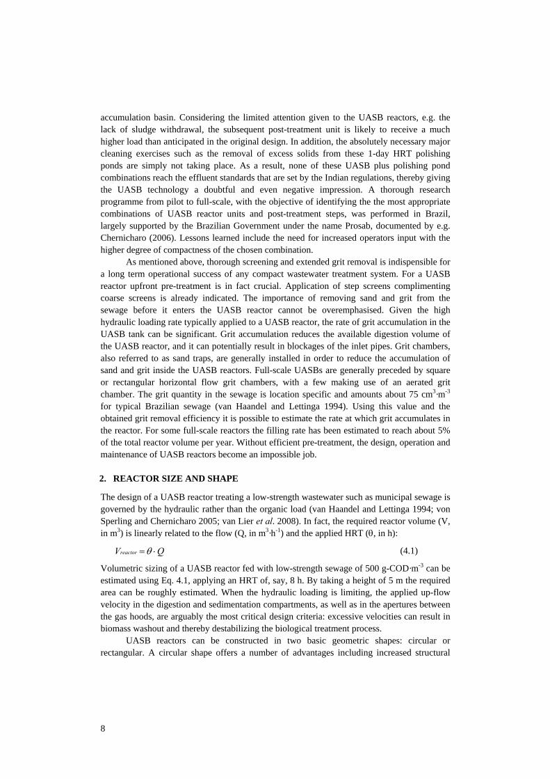
Two conflicting design requirements must be reconciled when the diameter of the inlet pipes is selected: (1) the velocity at the top of the pipe should be low enough to allow any entrained air to escape back up the pipe, and (2) the velocity should be high enough at the outlet of the pipe to prevent heavy inert suspended solids from settling in or around the outlet. As to the first design requirement, entrainment of air bubbles with the influent is unavoidable because of the turbulent freefall that occurs when the sewage passes over the influent weir in the FDB and can have a number of negative effects. In general, the impact on the biological conversion process will be minimal as the entrapped O2 will be immediately used by the facultative aerobic bacteria present in the sludge bed. An important detrimental effect is that the small air bubbles that are entrained with the sewage have a tendency to accumulate into large air pockets in the inlet pipes, especially at bends. These pockets can lead to temporary blockages of the inlet pipes. The air pockets eventually escape back up the inlet pipe but until, and as they do so, they prevent influent from entering into the blocked inlet pipe. If the FDB is designed correctly, i.e. a free fall overflow V-notch weir is installed with sufficient static head available, the formation of air pockets does not influence the (average) flow distribution over the individual pipes. The flow that was prevented from entering into the pipe will accumulate above it, increasing static head until the obstruction is cleared and thus will still enter through that specific pipe. However, if the FDB is designed without weirs or without sufficient static head, the formation of these air pockets will affect the flow to individual pipes. Fig. 4.9 shows examples of gas pockets that have formed in an inlet pipe escaping back up the pipe.
Pipe diameters must be wide enough for gas bubbles to escape upwards. Following the calculations according Talaia (2007), a gas bubble with a diameter exceeding 2 mm has a rise velocity of about 0.2 m·s-1. For most full-scale UASB STPs, a diameter of 100 mm will be sufficient to achieve this aim. As to the second design requirement, van Haandel and Lettinga (1994) have suggested using a design grit settling velocity of 0.3 m·s-1 for grit removal units. Therefore it is required to have a velocity at the outlet of the influent pipe that is greater than this to prevent the deposition of grit in the immediate vicinity of the outlet. To resolve the conflict between these two design requirements, instalment of inlet pipes with different inlet and outlet diameters is proposed (van Haandel and Lettinga 1994; Chernicharo 2007). The latter, obviously, will add to the costs. Very few full-scale reactors are equipped with inlets where the diameter of the pipe is reduced from top to bottom.
15
Fig. 4.9. Large air bubbles escaping from an inlet pipe resulting in the temporary blockage of the pipe.
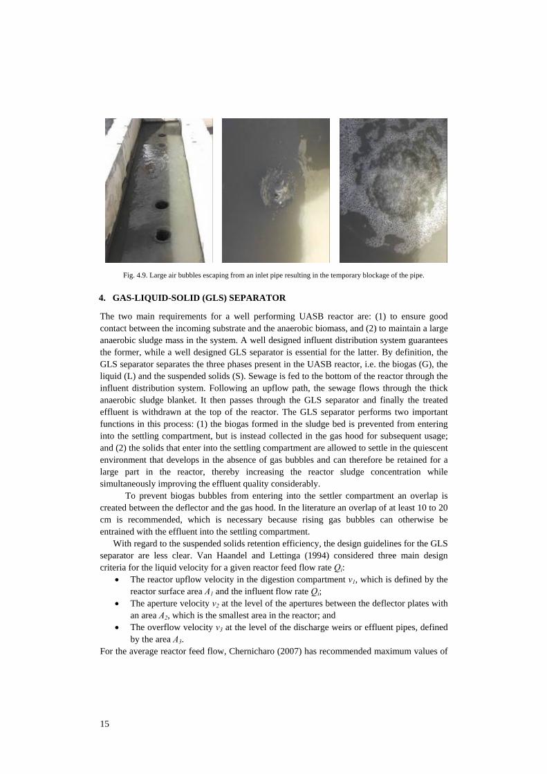
4. GAS-LIQUID-SOLID (GLS) SEPARATOR
The two main requirements for a well performing UASB reactor are: (1) to ensure good contact between the incoming substrate and the anaerobic biomass, and (2) to maintain a large anaerobic sludge mass in the system. A well designed influent distribution system guarantees the former, while a well designed GLS separator is essential for the latter. By definition, the GLS separator separates the three phases present in the UASB reactor, i.e. the biogas (G), the liquid (L) and the suspended solids (S). Sewage is fed to the bottom of the reactor through the influent distribution system. Following an upflow path, the sewage flows through the thick anaerobic sludge blanket. It then passes through the GLS separator and finally the treated effluent is withdrawn at the top of the reactor. The GLS separator performs two important functions in this process: (1) the biogas formed in the sludge bed is prevented from entering into the settling compartment, but is instead collected in the gas hood for subsequent usage; and (2) the solids that enter into the settling compartment are allowed to settle in the quiescent environment that develops in the absence of gas bubbles and can therefore be retained for a large part in the reactor, thereby increasing the reactor sludge concentration while simultaneously improving the effluent quality considerably.
To prevent biogas bubbles from entering into the settler compartment an overlap is created between the deflector and the gas hood. In the literature an overlap of at least 10 to 20 cm is recommended, which is necessary because rising gas bubbles can otherwise be entrained with the effluent into the settling compartment.
With regard to the suspended solids retention efficiency, the design guidelines for the GLS separator are less clear. Van Haandel and Lettinga (1994) considered three main design criteria for the liquid velocity for a given reactor feed flow rate Qi:
• The reactor upflow velocity in the digestion compartment v1, which is defined by the reactor surface area A1 and the influent flow rate Qi;
• The aperture velocity v2 at the level of the apertures between the deflector plates with an area A2, which is the smallest area in the reactor; and
• The overflow velocity v3 at the level of the discharge weirs or effluent pipes, defined by the area A3.
For the average reactor feed flow, Chernicharo (2007) has recommended maximum values of
16
0.7, 2.5 and 0.8 m·h-1 for v1, v2 and v3 respectively. Cavalcanti (2003) demonstrated at pilot scale that the installation of parallel plates above the conventional settler significantly improved suspended solids retention and thus also the maximum sludge concentration in the digestion zone. In these experiments average sludge concentrations (based on the total liquid reactor volume) of 25-35 g-TSS·l-1 were achieved, which is more or less in the same range as the 64 m3 pilot plant in Cali which retained 30-40 g-TSS·l-1. In Brazil, typical (full-scale STPs) values of 15-18 g-TSS·l-1 are observed for conventional GLS designs.
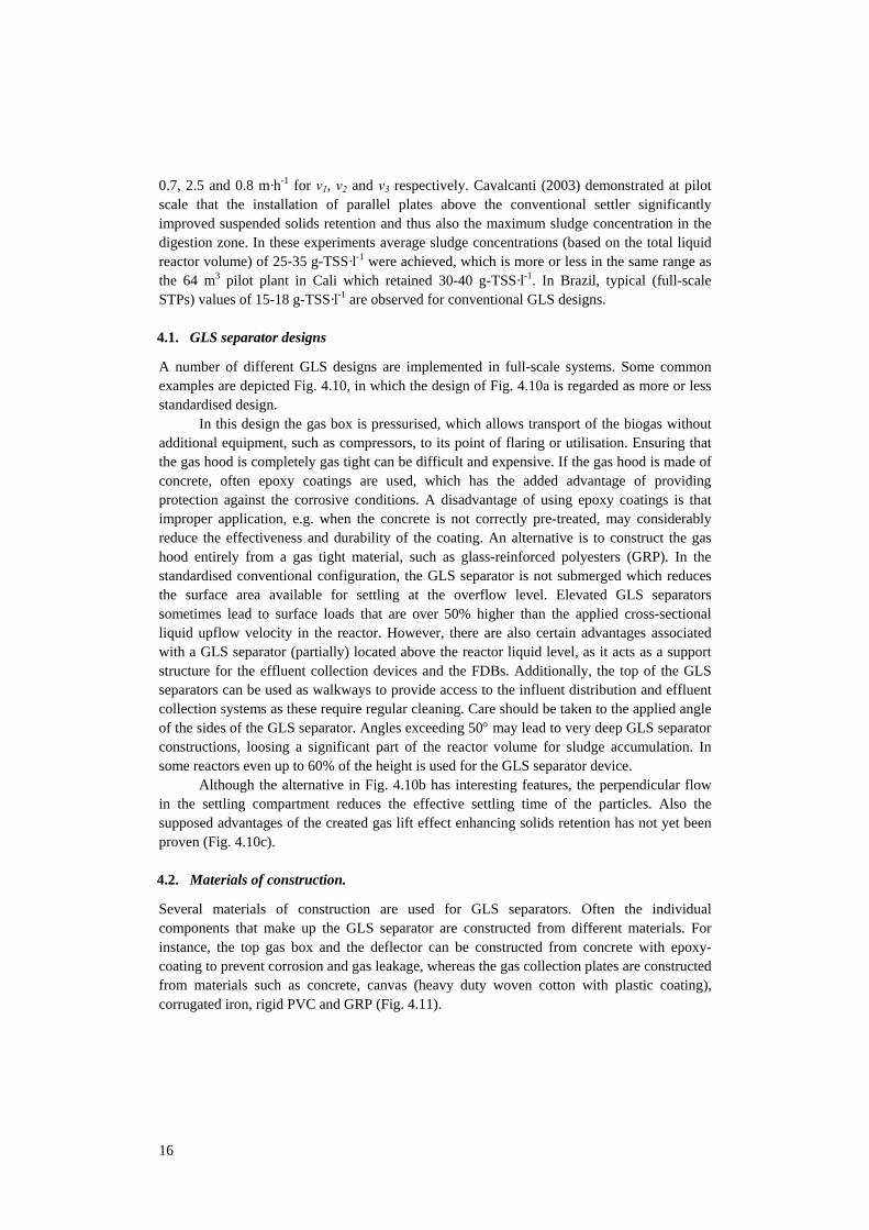
4.1. GLS separator designs
A number of different GLS designs are implemented in full-scale systems. Some common examples are depicted Fig. 4.10, in which the design of Fig. 4.10a is regarded as more or less standardised design.
In this design the gas box is pressurised, which allows transport of the biogas without additional equipment, such as compressors, to its point of flaring or utilisation. Ensuring that the gas hood is completely gas tight can be difficult and expensive. If the gas hood is made of concrete, often epoxy coatings are used, which has the added advantage of providing protection against the corrosive conditions. A disadvantage of using epoxy coatings is that improper application, e.g. when the concrete is not correctly pre-treated, may considerably reduce the effectiveness and durability of the coating. An alternative is to construct the gas hood entirely from a gas tight material, such as glass-reinforced polyesters (GRP). In the standardised conventional configuration, the GLS separator is not submerged which reduces the surface area available for settling at the overflow level. Elevated GLS separators sometimes lead to surface loads that are over 50% higher than the applied cross-sectional liquid upflow velocity in the reactor. However, there are also certain advantages associated with a GLS separator (partially) located above the reactor liquid level, as it acts as a support structure for the effluent collection devices and the FDBs. Additionally, the top of the GLS separators can be used as walkways to provide access to the influent distribution and effluent collection systems as these require regular cleaning. Care should be taken to the applied angle of the sides of the GLS separator. Angles exceeding 50° may lead to very deep GLS separator constructions, loosing a significant part of the reactor volume for sludge accumulation. In some reactors even up to 60% of the height is used for the GLS separator device.
Although the alternative in Fig. 4.10b has interesting features, the perpendicular flow in the settling compartment reduces the effective settling time of the particles. Also the supposed advantages of the created gas lift effect enhancing solids retention has not yet been proven (Fig. 4.10c).
4.2. Materials of construction.
Several materials of construction are used for GLS separators. Often the individual components that make up the GLS separator are constructed from different materials. For instance, the top gas box and the deflector can be constructed from concrete with epoxy-coating to prevent corrosion and gas leakage, whereas the gas collection plates are constructed from materials such as concrete, canvas (heavy duty woven cotton with plastic coating), corrugated iron, rigid PVC and GRP (Fig. 4.11).
17
Fig. 4.10. GLS separator designs: (a) the conventional design as installed in most full-scale UASB STPs, (b) the
alternative gas lift design with perpendicularly mounted effluent collection gutters, and (c) the hybrid design installed in several Brazilian reactors.
All materials are found to be more or less suitable with the exception of the corrugated
iron gas collection plates, which will fully corrode in several years of operation. Each material has its own pros and cons. Concrete gas collection plates require extensive form work and therefore result in high labour requirements. GRP plates can be pre-fabricated and are installed relatively easily, but on the other hand they are more expensive. PVC plates are prone to distortion or even rupture, but are relatively inexpensive to manufacture and install. The PVC-coated polyester sheets are relatively new on the UASB market (although frequently used for inflatable gas holders) and were pioneered in Brazil. The material selection for the GLS separator will be based on the local procurement and construction costs, as well as on the skill level of the civil contractor.
4.3. Deflector type
The main function of the deflector is, as the name indicates, to deflect the upflowing gas and solids away from the aperture to the settling zone and into the gas hood, where the gas will detach and the solids will settle back on the sludge bed. Different types of deflectors are constructed that mainly differ in the use of special devices for possible gas collection and conveyance (Fig. 4.12). The first deflector design, shown in Fig. 4.12a, has an inverted V-shape, allowing the biogas-liquid-solids mixture to enter into the deflector. The installation of pipes approximately 20 cm from the top of the deflector allows the transport of the biogas-liquid-solids mixture into the gas hood. Because of the position of the pipes below the deflector top a gas-liquid interface is present in the top part of the deflector. This makes the formation of a scum layer inevitable. Scum build-up may eventually result in the pipes becoming clogged, which can result in the uncontrolled discharge of gas over the bottom of the deflector, resulting in periodic escape of gas through the apertures into the settling compartment. The use of pipes to direct the biogas-liquid-solids mixture into the gas hoods
Gas
Gas
Gas SolidsLiquids
SolidsLiquids
LiquidsSolids
(a) (b)
(c)
18
Fig. 4.11. Materials of constructions used for GLS separators: (a) Corrugated iron, (b) concrete, (c) GRP, (d) canvas
(PVC-coated woven cotton), and (e) rigid PVC.
Fig. 4.12. Schematic representation of several deflector designs
may result in locally increased turbulence near the aperture in those sections of the deflector where the pipes are installed, which should be minimised.
The second design (shown in Fig. 4.12b) is very similar to the first except the pipes are located at the very top of the deflector, which prevents a gas-liquid interface from developing and therefore avoids the problems associated with scum formation.
The third design (Fig. 4.12c) differs from the previous two designs in that the bottom of the deflector is now closed. Hence there is no risk of a gas-liquid interface with consequential scum formation. However, as the bottom of the deflector is closed but not
d e
a b c
a b
c d
19
inclined, there is a distinct possibility that biogas will be entrained with the effluent flow into the settler section. This is especially likely because the deflector is never perfectly level and/or symmetrical, which will result localised gas escape over the length of the deflector.
The last design (Fig. 4.12d) is closed as well but an inclined bottom section is added. The biogas is therefore actively deflected into the gas collection compartment while there is no risk of a gas-liquid interface developing. On the other hand, the addition of a bottom part to the deflector results in an increased total deflector height compared to the first 3 designs. However, it must be noted that the sludge bed should be maintained below the widest point of the deflector, in order to prevent biogas production above the deflector where it can enter directly into the settling compartment. As it is difficult to control the exact height of the sludge bed, it is recommended to keep the maximum sludge bed height at least 30 cm below this widest point. It is therefore concluded that the additional height of the deflector with an inclined bottom does in fact not reduce the volume of digestion zone; without any problem the bottom site can be submerged in the sludge blanket zone.
5. EFFLUENT COLLECTION
Effluent should be collected as uniformly as possible from the top of the UASB reactor to ensure optimum performance of the GLS separator. The two main alternatives for the collection of effluent from the top of the UASB reactor are effluent gutters fitted with V-notch overflow weirs and submerged perforated pipes. Mostly, V-notch overflow weirs are preferred as they can be controlled and cleaned easily, guaranteeing an even upflow in the settling compartment. In order to ensure that effluent is drawn off uniformly from the surface of the reactor there should be sufficient head available at the V-notch weirs to allow the weir to be aligned. Van Haandel and Lettinga (1994) suggest a minimum liquid height of 25 mm, below which it becomes difficult to adjust the overflow weirs. The flow rate over a V-notch weir can be calculated using the equation for a triangular weir:
5/ 2 11.465 tan2
Q h α= ⋅ ⋅ (4.2)
where Q represents flow rate (m3·h-1), h liquid height at the weir (m), and α the angle. Assuming an angle of 90° is used, a head of 25 mm will result in a flow rate of 0.52 m-3·h-1 per V-notch. Knowing that the liquid velocity in the UASB reactor is normally 0.5-1.2 m·h-1, it can be calculated that there should be a V-notch for approximately every 1-2 m2 of overflow surface area. However, visual observations at full-scale UASB STPs showed an excessive number of V-notches in the installed effluent weirs. On the other hand, some full-scale reactors do not apply V-notches at all. Uneven withdrawal of effluent results in preferential flows in the settler section, which can result in an excessive loss of solids and the formation of dead zones in the reactor, these zones are subsequently not available for digestion.
The alternative of using submerged perforated pipes for the collection of effluent is only sporadically applied. The main advantage of this system is the less stringent levelling requirements. The flow rate through a circular opening can be calculated using the following equation:
2cQ C A g h= ⋅ ⋅ ⋅ ⋅ (4.3)
where Cc represents the contraction coefficient (0.66 for a circular opening), A represents area of the opening (m2), g gravitational acceleration coefficient (m·s-2), and h liquid height at the
20
weir (m). In order to prevent clogging of the circular openings, a minimum diameter of 30 mm is suggested. Using Eqs. 4.2 and 4.3 it can be demonstrated that flow through a V-notch at a liquid head of 25 mm is 75% higher than at a head of 20 mm, while for a similar increase in liquid head the increase in flow rate is only 12% when a perforated pipe is used. Hence a misalignment of only 5 mm over the length of a V-notch gutter, which for a typical gutter length of 20 m amounts to an alignment error of only 0.025%, may lead to a difference in local effluent overflow rates of 75%, while there will be only a 12% difference in flow rate when perforated pipes are used. Perforated pipes also reduce turbulence at the overflow weir and, thereby, reduce malodorous emissions at the overflow point.
It is often suggested that the need to periodically clean the openings due to clogging by solids is a disadvantage of the perforated pipe system. However, V-notch weirs are also prone to clogging especially when the number of V-notches installed is excessive, resulting in low flow rates per individual V-notch. Therefore, both systems require provisions to allow for their periodic cleaning. Arguably the main disadvantage of using perforated tubes is the build up of a scum layer on the surface of the settler. Therefore, provisions should be put in place for the removal of this scum layer especially if the reactor is covered which is increasingly the case. It should be noted that a scum layer will also build up on V-notch systems, whenever scum baffles are installed or regular access for cleaning is not possible due to the presence of a fixed reactor cover. Furthermore it is quite possible that the frequency of cleaning in the case of submerged pipes is low, provided that the aperture diameter and flow rate are sufficiently high, as scum will then be removed (“sucked in”) through the holes. A flow rate of at least 1 m3·h-1 should make the apertures reasonably self-cleaning. On the other hand, this relatively high flow will slightly affect the UASB effluent suspended solids content owing to the carry over of floating scum (see paragraph 7.1).
6. SLUDGE WITHDRAWAL AND SLUDGE SAMPLING
6.1. Sludge withdrawal.
One of the main conditions for a satisfactory treatment performance of a UASB STP is to maximize the anaerobic sludge mass in the system, while simultaneously preventing sludge losses with the effluent. UASB reactors can retain a maximum sludge mass that is dependent on the size of the digestion zone and the maximum sludge concentration, which in turn depends on the phase separator efficiency in retaining suspended solids, the nature of the retained sludge, the degree of digestibility, preferential liquid flow streams, sludge filtering capacity, etc. Once the maximum storage capacity of the UASB reactor is reached, excess sludge will have to be discharged, otherwise unintentional sludge wash-out will occur. Without intentional sludge discharge, the rate of suspended solids washout in the effluent will be equal to the net sludge production and entrapment rate and this will considerably increase effluent COD and TSS values. Therefore an efficient system to control the sludge blanket height is essential. This includes a reliable and accurate system for sludge withdrawal.
It is recommended that the excess sludge withdrawal system is designed for sludge to be removed from at least three levels in the reactor. One discharge location should be situated approximately 15-20 cm from the reactor floor, another should be located approximately at half way between the reactor floor and the lowest part of the GLS separator device, and the third one 50-75 cm beneath the widest point of the deflector, typically 1.5-2.0 m from the
21
reactor floor. In addition, a drain must be installed, as a provision to completely empty the reactor for maintenance purposes. If such drain is indeed installed, the lowest discharge point could be eliminated from the design. Instead of a bottom drain, 900 mm diameter manholes can be provided in a UASB reactor for regular cleaning of settled bottom sludge during operation and maintenance period. According to the authors, lack of this facility in all existing full-scale UASB-based STPs in India largely contributes to the observed failure of the system performance (Table 4.3, Sato et al. 2006).
For optimal performance of a UASB reactor it is important to discharge sludge with a low volumetric sludge activity, which in the case of a municipal UASB is located in the less dense flocculent upper layer. On the other hand, due to sedimentation of inert particulate material in the UASB reactor the inorganic sludge fraction of the bottom sludge will gradually increase. This will have two consequences: (1) the volumetric activity will decrease, and (2) the density of the sludge may increase to a point where the inlet pipes become blocked and/or removal of the sludge from the reactor becomes impossible. Therefore, the normal routine should be to discharge sludge from the upper levels and only occasionally from the lower level or drain to prevent the buildup of inerts.
In a number of full-scale UASB STPs, the installed sludge withdrawal system was inadequate, e.g. only the bottom withdrawal system was installed, which results in a continuous discharge of the most active part of the sludge bed. Another downside of this strategy is that the sludge density will eventually reduce to very low levels reaching only 20 kg-TSS·m-3, in contrast to values up to 60-100 kg-TSS·m-3 observed elsewhere. Also, a thick sludge bed layer has much better filtration capacities resulting in a much higher SS removal efficiency.
As to the layout of the sludge withdrawal system, 2-3 withdrawal pipes per discharge level are required, each with a single opening per pipe. Considering that the surface area of UASB reactors tends to be about 500 m2, the density of sludge withdrawal points is approximately 1 per every 100 m2.
The withdrawn excess sludge from an anaerobic sewage treatment reactor is well stabilised owing to the long SRTs and can be dried by applying sludge drying beds generally within a week (van Haandel and Lettinga 1994). No smell arise from the sludge drying beds.
6.2. Sludge sampling.
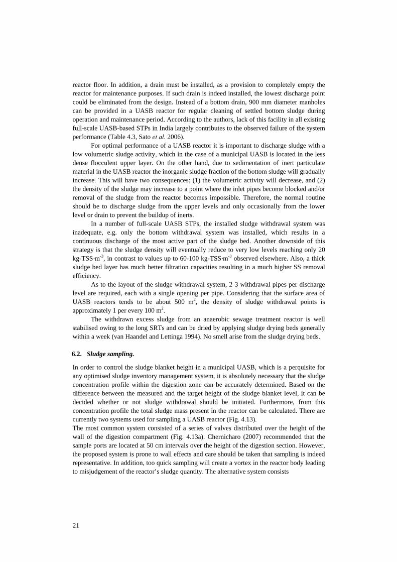
In order to control the sludge blanket height in a municipal UASB, which is a perquisite for any optimised sludge inventory management system, it is absolutely necessary that the sludge concentration profile within the digestion zone can be accurately determined. Based on the difference between the measured and the target height of the sludge blanket level, it can be decided whether or not sludge withdrawal should be initiated. Furthermore, from this concentration profile the total sludge mass present in the reactor can be calculated. There are currently two systems used for sampling a UASB reactor (Fig. 4.13). The most common system consisted of a series of valves distributed over the height of the wall of the digestion compartment (Fig. 4.13a). Chernicharo (2007) recommended that the sample ports are located at 50 cm intervals over the height of the digestion section. However, the proposed system is prone to wall effects and care should be taken that sampling is indeed representative. In addition, too quick sampling will create a vortex in the reactor body leading to misjudgement of the reactor’s sludge quantity. The alternative system consists
22
Fig. 4.13. Sludge sampling systems: (a) The most commonly employed system consisting of a series of sampling
connections distributed over the height of the wall of the digester, and (b) the recommended procedure of taking samples from the top through the gas hood.
of a sample opening installed in the top part of the GLS separator device; a hydraulic seal should be used to prevent the escape of biogas during sampling. A simple sampling device can be introduced via this opening (more sophisticated versions are available on the market), and samples can be withdrawn from any level.
7. SCUM REMOVAL
Scum is generally defined as a layer of floating material that develops at gas-liquid interfaces of bioreactors. The exact properties of the scum layer are highly dependent on the characteristics of the raw sewage. However, in general, the scum layer tends to be thin and somewhat fluid during the early stages of the development, but it gradually becomes very thick and viscous. The problems associated to scum formation are the following:
• Blockage of part of the effluent weirs, resulting in imbalanced effluent withdrawal; • Potential for anaerobic decay with associated odour problems, procreation of flies
and other unwanted vermin, and in general a very unpleasant appearance; and • Accumulation in the gas hood thereby disrupting the collection and removal of the
produced biogas, and potentially leading to uncontrolled loss of biogas to the settling section or even ruptures in the GLS system.
During pilot plant studies Halalsheh et al. (2005 and 2010) observed scum layers as thick as 1 m during the anaerobic treatment of concentrated sewage in Amman, Jordan. As a scum layer can develop wherever a gas-liquid interface is present, there are two possible locations in a UASB reactor where scum formation is a severe risk: (1) on top of the settler section, and (2) on the gas-liquid interface in the gas hood. The removal of scum from both locations is arguably the most troublesome operational procedure currently associated with municipal UASB reactors. Therefore, before discussing systems and procedures for scum removal, it should be pointed out that prevention of scum formation is much preferred over remedial measures. As scum formation is associated with, amongst others, the presence of free oil, grease and fats, hairs and fibres, it should be attempted to remove these constituents upfront at the headworks of the system. The use of fat traps, coarse and fine screening (6 mm), and aerated grit removal systems is highly recommended.
7.1. Scum in the settler section
Scum baffles were installed at many of the STPs with gutter systems for effluent withdrawal, as it has been suggested that the retention of scum results in a slight improvement in the effluent quality (van Haandel and Lettinga 1994). However, Souza et al. (2006) has shown that the production of scum under Latin American conditions is actually quite low at
a b
Gashood
Opening forsludge sampling
Sampling points
23
approximately 0.01 l·kg-CODapplied-1. Thus the installation of scum baffles is only necessary if
the UASB reactor is the only means of treatment, or when it is followed by a series of ponds, where scum may accumulate, cause odour problems, and is difficult to remove. If scum baffles or perforated pipes are installed, provisions should also be put in place to allow for the removal of the scum layer that will be retained on the surface of the settler section. One approach is to allow a scum layer to develop into a thick viscous layer for approximately 3 to 4 months at which point it can be manually removed from the surface of the settler section using shovels and wheel barrows. This system was effective although clearly a very unpleasant job and very labour intensive.
An alternative method is to install scum removal bowls every 2-3 m in the settler section. The bowls are connected to a gate valve, which, when opened, allows the surface of the settler section, with its associated scum layer, to be drained and sent to the post-treatment unit. Return of this scum to the UASB reactor is not recommended as it will immediately result in a novel scum build up.
In principle, scum layer build up can be prevented if scum baffles are not installed (Chernicharo et al. 2009). However, in several full-scale plants a thick scum layer developed irrespective the free outflow of the effluent (Fig. 4.14). This is probably due to the excessive number of V-notches, far exceeding the recommendations discussed previously. If the flow per V-notch is too low, there is a high risk of blockage of V-notches. In principle this can be remedied easily by cleaning of the effluent weirs with a brush where and when needed, provided the reactor’s surface is accessible. In the example of Fig. 4.14 the reactor was entirely covered with poured concrete and the settling section was only accessible by manholes. Therefore, in each design, provisions should be put in place to allow the removal of a scum layer.
7.2. Scum in the gas hood
The removal of scum from the gas hood is arguably an even more difficult task. Several methods have been implemented for this purpose, each with varying degrees of success. A commonly used method is the periodic removal of accumulated scum through access points (manholes) installed at regular intervals along the length of the GLS separator device. There are a number of disadvantages associated with this method:
• The access holes are so small that scum removal is very difficult, labour intensive, and with only partial results at best;
• Due to the risk of explosion and/or sulfide toxicity it is necessary to inert the gas hood prior to opening the covers as well as during the cleaning procedure. Although this safety provision is frequently disobeyed in practice;
• It is difficult to hermetically seal the access points after use. This is an absolute necessity, as otherwise biogas will escape to the environment resulting in environmental and safety issues (e.g. odour, H2S toxicity, explosion risks); and
• Finally if the gas hood is not hermetically sealed it is impossible to operate the gas hoods at sufficient overpressure (15 - 40 mbar) to allow for the transport the produced biogas to the gas treatment and utilisation facilities without the use of ventilators or compressors.
Another method that is commonly applied is spraying of the gas hood surface with water in an attempt to break the scum layer and disperse the scum. Unfortunately, this systems
24
Fig. 4.14. Images taken inside the settler of a fully close UASB system without scum layer baffles: (a) The clean
effluent gutter clearly visible during commissioning of the STP, and (b) a 40 cm scum layer developed after 1 year of operation.
was not effective at any of the known UASB reactors where the system was installed.
Recently, Chernicharo et al. (2009) proposed a novel system using the auto-generative gas pressure under the gas hood. The basic working mechanism relies on the sequential reduction and increase of pressure inside the gas hood to facilitate the removal of scum through weirs installed in the gas box. Excellent results under pilot conditions calls for full-scale trials. The drained scum can be diverted to the post-treatment step or to the sludge discharge line.
8. REACTOR COVERS AND EMISSION PREVENTION
The early full-scale UASB STPs were designed and built without covers on top of the settler sections. However due to concerns about odorous emissions from UASB reactors, the trend in more recent full-scale designs is to include covers. From the STPs investigated, 60% had covers installed. There are essentially two options for covering the settler section, i.e. either removable covers made from materials such as aluminium, GRP and thin concrete slabs, or having a fixed cover of cast in place concrete.
As discussed above, it is necessary to have access to the settler section for the regular cleaning of V-notch weirs or the openings in the effluent pipes, whichever are installed and for periodic scum removal if required. Therefore from an operation and maintenance perspective, the fixed cover is not recommended as it seriously limits access to the settler compartment. Considering that the primary reason for covering the settler section is odour control, it is interesting to note that practically all covered UASBs were not connected to a vent gas treatment system. Therefore, if the cover is not perfectly gas tight there will still be odour emissions although at a reduced rate. In fact, in most STPs it is observed that the source of most odour problems is coming from the raw sewage inlet chamber upstream of the coarse screens. To a lesser extent odour problems are observed from the effluent overflow channel including the free fall overflows to either the post-treatment unit or effluent outfall. Reactor coverage becomes increasingly important for addressing the greenhouse gas emissions that generally occur at the top part of anaerobic reactors where the anaerobic environment is exposed to air. Here the PCH4 drops from about 0.8 bar to about nil, releasing all dissolved CH4 at the effluent overflow weirs. In fact, up to 50% of the produced CH4 could be released to the atmosphere unless provisions are put in place to prevent this. The high amount of solubilised CH4 can be attributed to the low COD load of the sewage and the relatively low
a b
25
temperature most of the plants are operated at. At 20°C and 1 bar of CH4 partial pressure, about 33 l of CH4 is solubilised in 1 m3 of effluent (Wilhelm et al. 1977). Assuming a flow of 50,000 m3·d-1, a COD concentration of 500 mg·l-1, a COD removal efficiency of 75%, a PCH4 of 0.8 bar, and a specific CH4 production rate of 0.15 m3·kg-CODrem
-1, the amount of CH4 produced is estimated as 2813 m3·d-1 (i.e. 50,000 x 0.5 x 0.75 x 0.15), of which the solubilised CH4 is estimated as 1320 m3·d-1 (i.e. 50,000 x 0.033 x 0.8), equivalent to 47% of the total CH4 production. This will even get worse when more diluted sewage is treated, or the sewage temperature is lower, or less COD is removed. The specific CH4 production of 0.15 m3·kg-CODrem
-1 obviously depends on the biodegradability of the sewage and the amount of entrapped and converted primary sludge. Lettinga et al. (1993) and Uemura and Harada (2000), reported somewhat higher values, viz. 0.19 and 0.16 m3·kg-CODrom
-1, resulting in a higher recovery percentage.
CH4 emission prevention can be obtained by covering the reactor and using a low pressure to collect the accumulating gases, which are subsequently directed towards the flare or furnace for combustion. Alternatives to prevent atmospheric CH4 emission include the oxidation of CH4 in an aerated unit located on the top UASB reactor. This could be achieved by, for example, placing bio-rotors at the top of the UASB or combining a UASB with a post-treatment using activated sludge in a single tank (Fig. 4.15)
During the early developments of anaerobic sewage treatment, CH4 emission was simply ignored or not taken into consideration in the full-scale design because of ignorance and/or financial limitation. Nowadays, uncontrolled greenhouse gas emissions should be avoided and non-flaring of captured CH4 should be prohibited. If instead, all the energy is used, with the increasing energy prices and tradable CO2 credits, anaerobic sewage treatment will become an affordable investment for many developing countries.
At present, the produced biogas is hardly recovered and very few full-scale plants are equipped with a biogas motor. In most full-scale reactors the biogas is (or intended to be) flared. In general the biogas collection and disposal system is rather poor, with significant corrosion issues due to inappropriate material selection. In some cases, flares did not work and biogas was vented directly to the atmosphere. Furthermore, in most known STPs the installed gas meter fails and/or is not operational.
9. FUTURE OUTLOOK: TREATMENT OF CONCENTRATED SEWAGE
Domestic sewage is a dilute wastewater of complex characteristics, with a relatively high suspended solids content (i.e. a low CODsoluble/CODtotal ratio) and a low temperature. The suspended solids may constitute 50-65% of the total COD. Therefore, total COD conversion is largely limited by hydrolysis of particulate matter. Particularly when the sewage temperature drops to below 20ºC, the biological conversion capacity will determine the overall COD removal rather than the prevailing hydrodynamic conditions. In fact, because of the low temperature and the high TSS/COD ratio, the COD concentration range in which the HRT determines the volume of the UASB reactor (as shown in Eq. 4.1) is relatively small. When temperature drops and non-digested sludge starts to accumulate in the sludge bed, the hydrolytic and methanogenic capacity of the sludge bed will gradually decrease, deteriorating both particulate and soluble COD removal, and eventually leading to reactor failure. Apparently, the primary design criterion, even with dilute domestic sewage, is the reactor solids retention time (SRT), which should be above a minimum value in order to maintain the
26
(a) (b)
GAS OUT
INFLUENT
...... ........................AIR IN
EFFLUENT
ANAEROBICANAEROBIC
AEROBICAEROBIC
... ... ...... ...
......
GAS OUT
INFLUENT
...... ........................AIR IN
EFFLUENT
ANAEROBICANAEROBIC
AEROBICAEROBIC
...... ...... ............ ......
......
Fig. 4.15. BIOPAQ®UBox sewage treatment plant: (a) The schematic design showing a combined anaerobic treatment with activated sludge, and (b) a full-scale plant in Igaraçu do Tietê, Brazil, treating wastewater of 25.000 population equivalents (printed with permission of Paques)
methanogenic conversion capacity of the sludge. With dilute domestic sewage (COD below 1,000 mg·l-1) under tropical conditions (temperature above 20ºC), this condition will always be met. The prevailing SRT depends on various sewage characteristics, such as:
• Sewage temperature, • Influent suspended solids concentration, • Rate of solids digestion in the reactor, • Filtering capacity of the sludge bed, which are determined by the applied upflow
velocities and sludge characteristics, • Growth and decay of new sludge, • Sludge retention in the settler, determined by the applied liquid velocities, • Withdrawal of excess sludge.
The SRT can be calculated using Eq. 4.3,
sludgeexcesssludgeexcesseffleffl
reactorreactor
XQXQVXSRT
−−+=
... (4.4)
where X represents concentration of viable biomass (kg·m-3), V reactor volume (m3), and Q flow rate (m3·d-1). As a rule of thumb, the minimum SRT should always be more than 3 times the doubling time (Td) of the biomass responsible for the rate limiting step. With dilute domestic sewage under tropical conditions, these are the methanogens, with an estimated Td at 25ºC of about 10 days. Therefore, SRTs of existing full-scale sewage treatment systems will never be below 30 days. The impact of temperature on the required SRT in the UASB reactor is illustrated in Fig. 4.16. Realising the importance of the SRT, it becomes clear that the conventional UASB reactor design for municipal wastewater needs reconsideration when temperature drops and COD exceeds 1,000 mg·l-1. In many arid climate countries with limited water supply, such as. Middle East, Northern Africa and Arabic peninsula, sewage COD
27
0
20
40
60
80
100
120
140
160
180
10 15 20 25 30 35 40 45
Temperature [°C]
SRT
for s
tabi
lized
slu
dge
[day
s]
0
20
40
60
80
100
120
140
160
180
10 15 20 25 30 35 40 45
Temperature [°C]
SRT
for s
tabi
lized
slu
dge
[day
s]
Fig. 4.16. Required SRT for domestic sewage treatment as a function of temperature.
concentrations range 1,000–2,500 mg·l-1. Furthermore, the temperate climates in the Middle East and Northern Africa are characterised by cold winters, particularly in mountainous areas.
Recent experiences in Jordan and Palestine show municipal sewage COD concentrations reaching 2,500 mg-COD·l-1 at a TSS/COD ratio of 0.6 (Mahmoud et al. 2008), whereas winter temperatures may drop to 15ºC. Applying the conventional UASB reactor design, the HRT needs to be increased to 20-24 h (Halalsheh et al. 2005 and 2010). This, obviously, will affect the hydrodynamics of the system requiring changes in influent distribution to prevent short-circuiting. Alternatively, the large suspended solids load can be addressed in separate reactor units such as a primary clarifier or enhanced solids removal in upflow filter systems, coupled to a sludge digester (Elmitwalli et al. 2002a and b). A novel approach is to link the UASB reactor to a coupled digester with sludge exchange (Mahmoud et al. 2004). With the latter system, accumulating solids will be digested at higher temperatures, whereas the methanogenic activity in the reactor will be increased by a return digested sludge flow.
Recently, the first full-scale reactor in the Middle East region has been started up (Nada et al. 2006) in Fayoum, south of Cairo, Egypt. The design is based on the conventional approach taking into account the relatively high strength of the sewage, resulting in a somewhat higher HRT with an average of 12 h. Pilot trials in Amman showed the feasibility of the system as an ideal pre-treatment method for a low cost reduction in the COD load, while generating energy for post-treatment. Table 4.5 summarises the key influent characterisitics and the most important results (Halalsheh et al. 2005 and 2010).
Although prospects for full-scale application in Amman look very promising (Table 4.5), it was decided to change the former pond system into a modern activated sludge plant. With regard to sustainability in domestic sewage treatment this decision is considered a wasted opportunity, particularly as more concentrated municipal wastewaters are in fact ideal for anaerobic pre-treatment. The recovered energy can then be beneficially used at the treatment site for extensive treatment up to discharge or reuse standards. Any excess energy may serve as power supply for irrigation pumps or for settlements in the vicinity of the plant.
10. CONCLUDING REMARKS
The UASB system has developed into a mature technology that has been applied successfully
28
Table 4.5. UASB pilot trials at Amman-Zarqa, waste stabilisation pond site ‘Khirbet As Samra’, Jordan.
Average influent characteristics Treatment performance (including post-clarification)
COD Removal up to 80% BOD Removal up to 85% SS Removal up to 80% Pathogens negligible CH4 production 0.15 m3·CODrem
-1
Potential CH4 production 27,000 m3·d-1
(equivalent to ~5 MW, assuming 40% efficiency)
Note: Flow estimates concern the year 2000 (Ammary 2007; Halalsheh et al. 2005). Flow projections for 2025 are exceeding 425.000 m3·d-1 (Ammary 2007)
for the treatment of municipal sewage in regions with a warm climate. However, the performance of the large STPs built in the last ten years is inferior to that of the original pilot- and full-scale STPs built in the late 1980s and early 1990s. In all cases the inferior performance can be explained by poor design and construction, insufficient or unqualified operator attendance or to the presence of high SO4
2- concentrations in the sewage. Despite publication of the recommended design guidelines by van Haandel and Lettinga (1994), many of the commissioned full-scale UASB systems have structural shortcomings. The hydraulic profiles of some plants were insufficient to achieve uniform distribution of flow and flow division devices, such as the FDB, are poorly constructed. In general, the GLS separators are better designed, although the efficacy of the gas lift designs is questionable when a low strength wastewater such as sewage is treated, as the gas production rate may be too low to induce the required mammoth flow. Effluent collection remains problematic, particularly in UASB reactors with a fixed cover preventing easy access to the effluent weirs for cleaning. Scum removal from the gas hood is without doubt the most troublesome design issue. Only a very few full-scale reactors manage to operate without aggravating scum removal problems.
As to the subject of insufficient/unqualified operator attendance, this might be due to earlier publications where the UASB was portrayed as a low cost and low maintenance solution. Whereas the UASB is indeed a low maintenance system, low maintenance does not equal the absence of maintenance, which seems to be the meaning taken all too often. The best operating full-scale reactors that were designed in the past two decades for sewage temperatures between 17 and 27°C achieve removal efficiencies of nearly 67, 70 and 75% for COD, BOD and TSS, respectively, which are a little bit below the projected design values in Table 4.4. A further increase by 6-10% in removal efficiency seems possible when all critical design features are taken into account and operator attendance is maximised.
Considering the present concern on fossil fuel consumption, anaerobic sewage treatment offers a feasible alternative for treating the huge flow of domestic and municipal wastewaters in many parts of the world. In light of the current green house gas discussion, recovery of all produced CH4 should be an intrinsic part of the treatment plant design. Owing to its compactness, high-rate anaerobic sewage treatment can be applied in the urban areas as well. The latter will lead to huge costs reduction in constructing sewerage networks, pumping stations, and conveyance networks. It must be realised that in 2000 only 35% of the produced municipal wastewaters in Asia were treated, whereas in Latin America this value was only 15% (WHO/UNICEF 2000). Since then, advancements are limited and largely vary (Chile
29
reaching 80% and Haiti remaining at 10% or less). In Africa, the generated wastewaters are hardly collected and sewage treatment, with the exception the Mediterranean part and South Africa, is nearly absent. With the increase in basic understanding of the anaerobic process and increase in the number of full-scale experiences at any scale, anaerobic treatment will undoubtedly become one of the prime methods for treating organically polluted wastewaters streams.
11. REFERENCES
Ammary, B.Y. (2007) Wastewater reuse in Jordan: present status and future plans. Desalination 211, 164-176.
Cavalcanti, P.F.F. (2003) Integrated Application of the UASB Reactor and Ponds for Domestic Sewage Treatment in Tropical Regions. Thesis, Wageningen University, the Netherlands.
Chernicharo, C.A.L. (2006) Post-treatment options for the anaerobic treatment of domestic wastewater. Rev. Environ. Sci. Biotechnol. 5(1), 73–92.
Chernicharo, C.A., Almeida, P.G., Lobato, L.C., Couto, T.C., Borges, J.M., Lacerda Y.S. (2009) Experience with the design and start up of two full-scale UASB plants in Brazil: enhancements and drawbacks, Wat. Sci. Technol. 60(2), 507-515.
CPCB (2003) Status of Sewage Treatment Plants in Ganga Basin. Central Pollution Control Board (CPCB), Ministry of Environments & Forests (MoEF), Delhi, India.
CPCB (2007) Evaluation of Operation and Maintenance of Sewage Treatment Plants in India. Central Pollution Control Board (CPCB), Ministry of Environments & Forests (MoEF), Delhi, India.
Draaijer, H., Pereboom, J.H.F. and Sontakke, V.N. (1994) Four years experience with the 5 MLD UASB reactor for sewage treatment at Kanpur, India. Proceedings of 7th International Symposium on Anaerobic Digestion, January 23-37, Cape Town, South Africa.
Draaijer, H., Maas, J.A.W., Schaapman, J.E. and Khan, A. (1992) Performance of the 5 MLD UASB reactor for sewage treatment in Kanpur, India. Wat. Sci. Technol. 25(7), 123-133.
Elmitwalli, T.A., Sklyar, V., Zeeman, G., Lettinga G., (2002a) Low temperature pre-treatment of domestic sewage in an anaerobic hybrid or an anaerobic filter reactor. Bioresource Technol. 82, 233-239.
Elmitwalli, T.A., Oanh, K.L.T., Zeeman, G., Lettinga, G. (2002b) Treatment of domestic sewage in a two-step anaerobic filter/ anaerobic hybrid system at low temperature. Wat. Res. 36 (9), 2225–2232
Halalsheh, M., Sawajneh, Z., Zu’bi, M., Zeeman, G., van Lier J.B., Fayyad, M. and Lettinga G. (2005) Treatment of strong domestic sewage in a 96 m3 UASB reactor operated at ambient temperatures: two-stage versus single-stage reactor. Bioresource Technol. 96, 577-585.
Halalsheh, M., Zeeman, G., Lettinga, G. and van Lier, J.B. (2010) Anaerobic Pre-treatment of Strong Sewage. VDM publishing House Ltd, Mauritius, In Press
Lettinga, G., de Man, A., van der Last, A.R.M., Wiegant, W., Van Knippenberg, K., Frijns, J. and van Buuren, J.C.L. (1993) Anaerobic treatment of domestic sewage and wastewater. Wat. Sci. Technol. 27(9), 67-93.
Mahmoud, N., Zeeman, G., Gijzen, H. and Lettinga, G. (2004) Anaerobic sewage treatment in a one-stage UASB reactor and a combined UASB-digester system. Wat. Res. 38(9), 2348-2358.
Mahmoud, N., Zeeman, G. and van Lier J.B. (2008) Adapting UASB technology for sewage treatment in Palestine and Jordan. Wat. Sci. Technol. 57(3), 361-366.
Nada, T., Ali, H.I., Farid, M.N., El-Gohary, F.A and Moawad, A. (2006) A full-scale application for anaerobic wastewater treatment technology (up-flow anaerobic sludge blanket UASB) in Egypt. Conference National Research Centre, March 13-15, Cairo, Egypt.
Oliveira, S. C. and von Sperling, M. (2009) Performance evaluation of UASB reactor systems with and without post-treatment. Wat. Sci. Technol. 59(7), 1299-1306.
Royal Haskoning Consulting Engineers (1989) Anaerobic Treatment of Domestic Wastewater under Tropical Conditions - Final Report. Royal Dutch Consulting Engineers and Architects.
30
Sato, N., Okubo, T. Onodera T, Ohashi, A, Harada, H. (2006) Prospects for a self-sustainable sewage treatment system: A case study on full-scale UASB system in India’s Yamuna River Basin, J. Environ. Management. 80(3), 198–207.
Schellinkhout, A. and Collazos, C.J. (1992) Full-scale application of the UASB technology for sewage treatment. Wat. Sci. Technol. 25(7), 159-166.
Schellinkhout A. and Osorio E. (1994) Long-term experience with the UASB technology for sewage treatment on large scale. Proceedings of 7th International. Symposium. on Anaerobic Digestion, January 23-37, Cape Town, South Africa.
Schellinkhout, A., Lettinga, G., van Velsen, A.F.M., Louwe Kooijmans, J. and Rodriguez, G. (1985) The application of the UASB-reactor for the direct anaerobic treatment of domestic waste water under tropical conditions. Proceedings of Seminar on Anaerobic Treatment of Sewage, M.S. Switzenbaum (ed.), 259-276, June 27-28, Amherst, USA.
Sharma, S. (2002) Wouldn’t you like a nice anaerobic sludge blanket? www.cleanganga.com, visited 2007.
Souza, C.L., Silva, S.Q., Aquino, S.F., and Chernicharo, C.A.L., (2006) Production and characterization of scum and its role in odour control in UASB reactors treating domestic wastewater. Wat. Sci. Technol. (54), 201-208.
Talaia, M.A.R. (2007) Terminal velocity of a bubble rise in a liquid column. World Acad. Sci., Eng. and Technol. 28, 264-268.
Tare, V. and Nema, A. (2006) Sewage treatment through UASB technology - expectations and reality. Proceedings of 22nd National convention on Environmental Engineering, Institution of Public Health Engineering and IT-BHU, Varanasi, April 7, 2006.
Uemura, S. and Harada, H. (2000) Treatment of sewage by a UASB reactor under moderate to low temperature conditions. Bioresource Technol. 72(3), 275-283
van Haandel, A.C. and Lettinga, G. (1994) Anaerobic Sewage Treatment. A Practical Guide for Regions with a Hot Climate. John Wiley and Sons. Chichester, pp. 84.
van Lier, J.B., Mahmoud, N. and Zeeman G. (2008) Anaerobic wastewater treatment. In: M. Henze, M.C.M. van Loosdrecht, G.A. Ekama, D. Brdjanovic (eds.), Biological Wastewater Treatment, Principles, Modelling and Design, Chapter 16, ISBN: 9781843391883, IWA Publishing, London, UK, p. 415-456.
Vieira, S.M.M. and Souza, M.E. (1986) Development of technology for the use of the UASB reactor in domestic sewage treatment. Wat. Sci. Technol. 18(12), 109-121.
von Sperling, M. and Chemicharo, C.A.L. (2005) Biological Wastewater Treatment in Warm Climate Regions (Vol. 1). IWA Publishing London. pp. 750-751.
WHO/Unicef (2000) Global Water Supply and Sanitation Assessment 2000 Report. World Health Organisation, United Nations Children’s Fund, Geneva, p. 80.
Wiegant, W.M.T. Kalker J.J., Sontakke, V.N. Zwaag R.R. 1999. Full scale experience with tannery water management: an integrated approach. Wat. Sci. Technol. 39(5), 169–176.
Wilhelm, E., Battino, R., and Wilcock, R.J. (1977) Low-pressure solubility of gases in liquid water. Chem. Rev. 77, 219–262.