04--00--1 Vol. 1 AUXILIARY POWER UNIT Table of Contents REV 3, May 03/05 Flight Crew Operating Manual CSP C--013--067 CHAPTER 4 ---AUXILIARY POWER UNIT Page TABLE OF CONTENTS 04--00 Table of Contents 04--00--1 INTRODUCTION 04--10 Introduction 04--10--1 APU POWER PLANT 04--20 APU Power Plant 04--20--1 Engine 04--20--1 Gearbox 04--20--1 SYSTEMS 04--30 Systems 04--30--1 Lubrication 04--30--1 Fuel 04--30--1 Ignition and Starting 04--30--1 Air Intake and Exhaust 04--30--1 CONTROL 04--40 Controls 04--40--1 Starting 04--40--1 Stopping 04--40--1 Protective Shutdown 04--40--6 System Circuit Breakers 04--40--7 LIST OF ILLUSTRATIONS INTRODUCTION Figure04--10--1 Auxiliary Power Unit -- Introduction 04--10--2 Figure04--10--2 APU Altitude and Airspeed Envelope 04--10--3 Figure04--10--3 Pneumatic Flow 04--10--4 Figure04--10--4 APU Start and Operating Limits 04--10--5 Figure04--10--5 APU Door Position 04--10--6 Figure04--10--6 EGT Shutdown Schedule 04--10--7 SYSTEMS Figure04--30--1 APU Controls and ECU Interface 04--30--2
Transcript
04--00--1Vol. 1AUXILIARY POWER UNIT
Table of Contents REV 3, May 03/05
Flight Crew Operating ManualCSP C--013--067
CHAPTER 4 ---AUXILIARY POWER UNIT
Page
TABLE OF CONTENTS 04--00Table of Contents 04--00--1
INTRODUCTION 04--10Introduction 04--10--1
APU POWER PLANT 04--20APU Power Plant 04--20--1
Engine 04--20--1Gearbox 04--20--1
SYSTEMS 04--30Systems 04--30--1
Lubrication 04--30--1Fuel 04--30--1Ignition and Starting 04--30--1Air Intake and Exhaust 04--30--1
INTRODUCTIONFigure 04--10--1 Auxiliary Power Unit -- Introduction 04--10--2Figure 04--10--2 APU Altitude and Airspeed Envelope 04--10--3Figure 04--10--3 Pneumatic Flow 04--10--4Figure 04--10--4 APU Start and Operating Limits 04--10--5Figure 04--10--5 APU Door Position 04--10--6Figure 04--10--6 EGT Shutdown Schedule 04--10--7
SYSTEMSFigure 04--30--1 APU Controls and ECU Interface 04--30--2
04--00--2Vol. 1AUXILIARY POWER UNIT
Table of Contents REV 3, May 03/05
Flight Crew Operating ManualCSP C--013--067
CONTROLFigure 04--40--1 Auxiliary Power Unit -- Control 04--40--2Figure 04--40--2 EICAS Auxiliary Power Unit Indications -- Primary 04--40--3Figure 04--40--3 Auxiliary Power Unit and Indications -- Status 04--40--4Figure 04--40--4 APU Start Sequence 04--40--5
04--10--1Vol. 1AUXILIARY POWER UNIT
Introduction REV 3, May 03/05
Flight Crew Operating ManualCSP C--013--067
1. INTRODUCTION
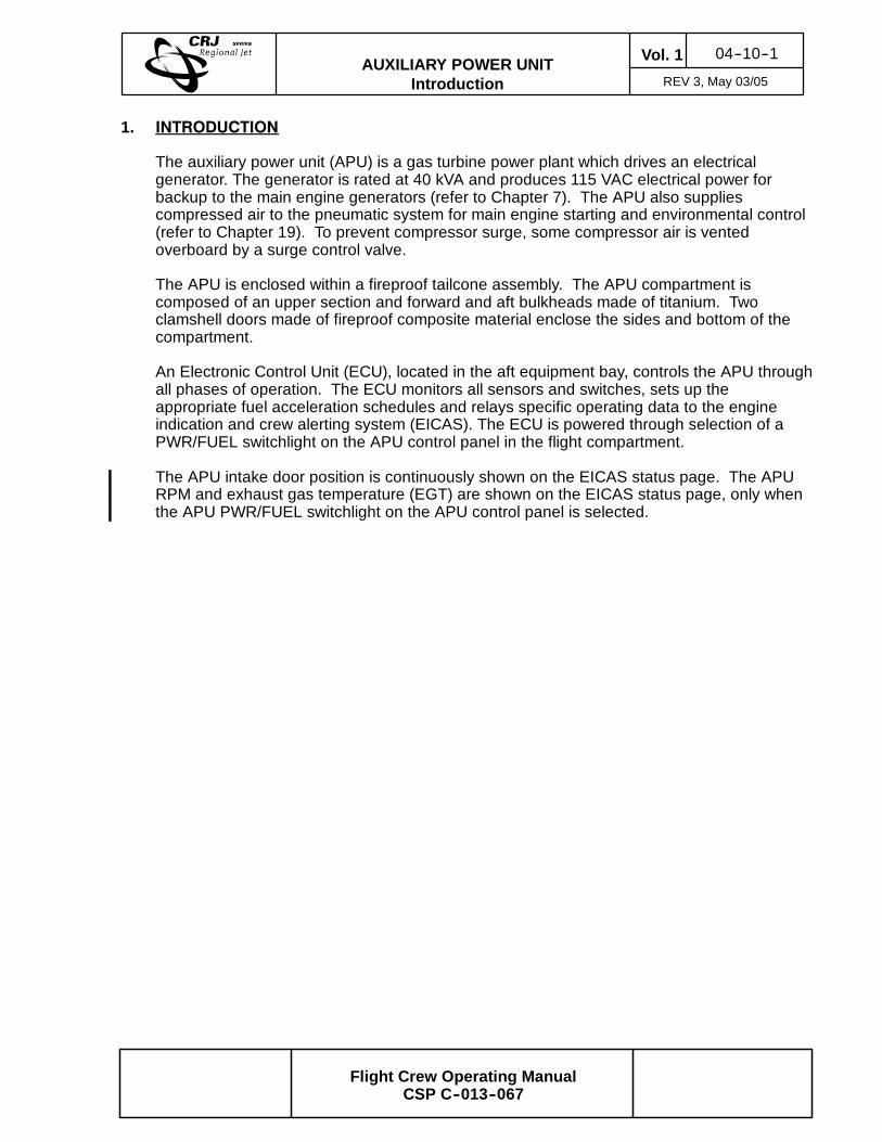
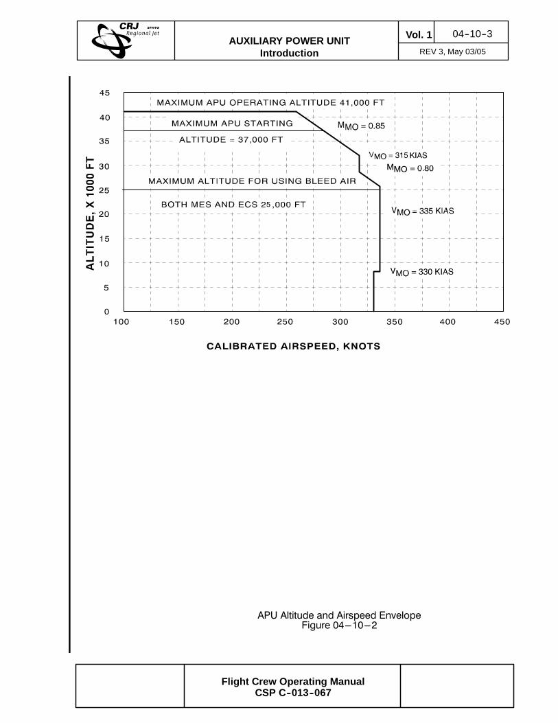
The auxiliary power unit (APU) is a gas turbine power plant which drives an electricalgenerator. The generator is rated at 40 kVA and produces 115 VAC electrical power forbackup to the main engine generators (refer to Chapter 7). The APU also suppliescompressed air to the pneumatic system for main engine starting and environmental control(refer to Chapter 19). To prevent compressor surge, some compressor air is ventedoverboard by a surge control valve.
The APU is enclosed within a fireproof tailcone assembly. The APU compartment iscomposed of an upper section and forward and aft bulkheads made of titanium. Twoclamshell doors made of fireproof composite material enclose the sides and bottom of thecompartment.
An Electronic Control Unit (ECU), located in the aft equipment bay, controls the APU throughall phases of operation. The ECU monitors all sensors and switches, sets up theappropriate fuel acceleration schedules and relays specific operating data to the engineindication and crew alerting system (EICAS). The ECU is powered through selection of aPWR/FUEL switchlight on the APU control panel in the flight compartment.
The APU intake door position is continuously shown on the EICAS status page. The APURPM and exhaust gas temperature (EGT) are shown on the EICAS status page, only whenthe APU PWR/FUEL switchlight on the APU control panel is selected.
04--10--2Vol. 1AUXILIARY POWER UNIT
Introduction Sep 09/02
Flight Crew Operating ManualCSP C--013--067
Auxiliary Power Unit --- IntroductionFigure 04---10---1
AIR INLET
EXHAUST
IGNITIONUNIT
OIL COOLER
GENERATOR
STARTER
PNEUMATICDUCT
SURGE CONTROLVALVE
04--10--3Vol. 1AUXILIARY POWER UNIT
Introduction REV 3, May 03/05
Flight Crew Operating ManualCSP C--013--067
APU Altitude and Airspeed EnvelopeFigure 04---10---2
04--10--4Vol. 1AUXILIARY POWER UNIT
Introduction REV 3, May 03/05
Flight Crew Operating ManualCSP C--013--067
Pneumatic FlowFigure 04---10---3
STA
RTER
AIR
VALVE
HIGH
PRESSURE
PORT
APU
HIGH
PRESSURE
VALVE
HIGH
PRESSURE
PORT
AIR
TURBINE
STA
RTER
AIR
COND
WING
A/IVALVE
WING
ANTI--ICE
LOW
PRESSURE
PORT
AIR
TURBINE
STA
RTER
BLE
EDSOURCE
BOTHENG
LENG
APU
(AUTO
MATIC
OR
MANUAL)
COWL
ANTI--ICE
LEFTENGINE
RENG
RIGHTENGINE
COWL
ANTI--ICE
LOW
PRESSURE
PORT
WING
ANTI--ICE
WING
A/IVALVE
AIR
COND
BLE
ED
ISOLATION
VALVE
PRSOV
PRSOV
GENERATO
R
GROUND
AIR
SUPPLY
LOADCONTROL
VALVE(LCV)
STA
RTER
AIR
VALVE
HIGH
PRESSURE
VALVE
ON
OFF
GENERATO
ROUTPUT
TOBUSDISTRIBUTION
GENERATO
RCONTROLUNIT
(GCU)
RPM
EGT
APUGEN
SELE
CTO
R
APUGEN
APU
ELE
CTRONIC
CONTROLUNIT
(ECU)
OFF/
RESET
AUTO
E P
04--10--5Vol. 1AUXILIARY POWER UNIT
Introduction REV 3, May 03/05
Flight Crew Operating ManualCSP C--013--067
APU Start and Operating LimitsFigure 04---10---4
--5,000--100 --80 --60 --40 --20 0 20 40 60
0
5,000
10,000
15,000
20,000
25,000
30,000
35,000
40,000
45,000
(--1,000 feet)
APU Generator LoadingLimit (41,000)
APU Altitude StartingLimit (37,000)
APU MES and ECS BleedAltitude Limit (25,000)
Surge Valve ClosedBelow 17,000 FT
Ground StartingAltitude Limit(15,000)
PR
ES
SU
RE
ALT
ITU
DE
,FE
ET
STATIC AIR TEMPERATURE, CELSIUS
04--10--6Vol. 1AUXILIARY POWER UNIT
Introduction REV 3, May 03/05
Flight Crew Operating ManualCSP C--013--067
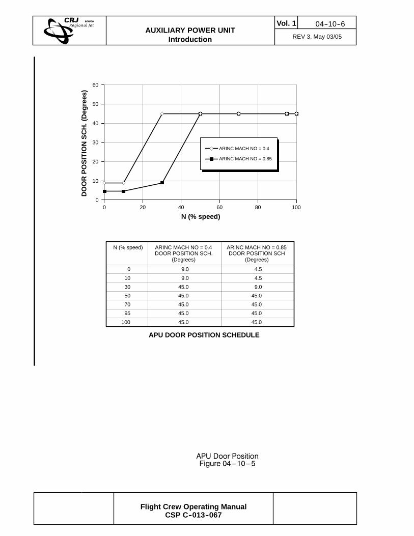
APU Door PositionFigure 04---10---5
00
DO
OR
PO
SIT
ION
SC
H.(
Deg
rees
)
10
20
30
40
50
60
20 40 60 80 100
ARINC MACH NO = 0.4
ARINC MACH NO = 0.85
N (% speed) ARINC MACH NO = 0.4DOOR POSITION SCH.
(Degrees)
0
10
30
50
70
95
100
9.0
9.0
45.0
45.0
45.0
45.0
45.0
ARINC MACH NO = 0.85DOOR POSITION SCH
(Degrees)
4.5
4.5
9.0
45.0
45.0
45.0
45.0
APU DOOR POSITION SCHEDULE
N (% speed)
04--10--7Vol. 1AUXILIARY POWER UNIT
Introduction REV 3, May 03/05
Flight Crew Operating ManualCSP C--013--067
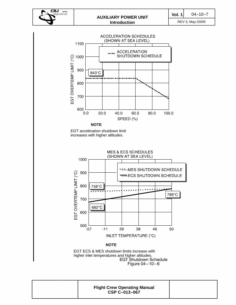
EGT Shutdown ScheduleFigure 04---10---6
NOTE
EGT acceleration shutdown limitincreases with higher altitudes.
NOTE
EGT ECS & MES shutdown limits increase withhigher inlet temperatures and higher altitudes.
04--10--8Vol. 1AUXILIARY POWER UNIT
Introduction REV 3, May 03/05
Flight Crew Operating ManualCSP C--013--067
THIS PAGE INTENTIONALLY LEFT BLANK
04--20--1Vol. 1AUXILIARY POWER UNIT
Power Plant Sep 09/02
Flight Crew Operating ManualCSP C--013--067
1. APU POWER PLANT
The APU power plant consists of a gas turbine engine and gearbox.
A. Engine
The engine is a single-shaft, constant speed design, consisting of a compressor, acombustor and a two-stage turbine. The compressor draws large volumes of airthrough the inlet ducting and delivers it under pressure to the combustor. Fuel from theleft collector tank is added to the high pressure air and ignited, increasing the energy ofthe airflow. The high velocity, high temperature gasses are delivered to the turbinesection. The turbine converts the high velocity gasses into mechanical energy to drivethe compressor and gearbox.
B. Gearbox
The gearbox reduces the turbine shaft rpm to a speed suitable to operate the gearboxmounted accessories. Accessories include the lubrication module, fuel control unit,electric starter and generator. The gearbox has an integral oil sump. The oil level canbe checked using a sight glass on the oil filler assembly.
04--20--2Vol. 1AUXILIARY POWER UNIT
Power Plant Sep 09/02
Flight Crew Operating ManualCSP C--013--067
THIS PAGE INTENTIONALLY LEFT BLANK
04--30--1Vol. 1AUXILIARY POWER UNIT
Systems REV 3, May 03/05
Flight Crew Operating ManualCSP C--013--067
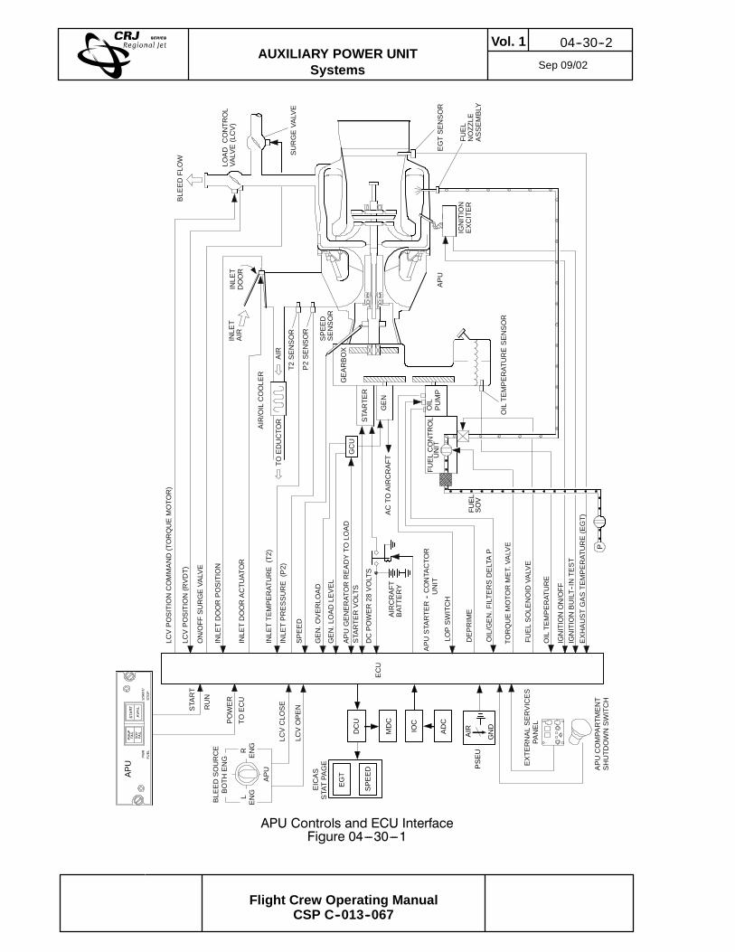
1. SYSTEMS
The APU consists of a lubrication system, fuel system, ignition and starting systems, and anair intake and exhaust.
A. Lubrication
The lubricating system consists of a mechanically driven lubrication module, oil filter, oilcooler, low oil pressure switch, oil temperature sensor and a deprime solenoid. Thelube module provides pressurized oil to the power plant, gearbox and generator forlubrication and heat removal. To ease starting under cold conditions, a de-primesolenoid allows vent air to enter the lube pump to reduce starter motor drag.
B. Fuel
Fuel is supplied to a fuel control unit from the left collector tank by a dedicated APU fuelpump (refer to Chapter 13). The fuel control unit starts, stops and modulates the flow offuel to the APU in response to commands from the ECU.
C. Ignition and Starting
The ignition and starter systems are controlled by the ECU. The ECU commands theDC starter motor to rotate the power plant. The starter accelerates the power plant to aspecific speed where the ECU introduces fuel to the combustor. The ignition system isused to ignite the fuel/air mixture in the combustor which further accelerates the powerplant. As the APU accelerates toward the onspeed condition, the starter is disengaged.When the APU reaches normal operating speed, the ignition is turned off. At this pointthe engine becomes self sustaining.
D. Air Intake and Exhaust
The air inlet door is located in the upper right side of the rear fuselage and is controlledby the ECU. When open, the door provides ram air for APU operation and oil cooling.On the ground, the air inlet door has only two positions, closed or open (0 and 45degrees). In flight, during APU start, the ECU limits the door position in response toAPU engine rpm and aircraft speed. This prevents excessive amounts of ram air whichcould cause the APU to flameout. When the APU is not operating, the door remainsclosed to prevent windmilling of the compressor. The inlet door also serves as a barrierin the event of fire. The exhaust duct is composed of stainless steel and is centered inthe tailcone.
04--30--2Vol. 1AUXILIARY POWER UNIT
Systems Sep 09/02
Flight Crew Operating ManualCSP C--013--067
APU Controls and ECU InterfaceFigure 04---30---1
PWR
FUEL
START/
STO
P
APU
LENG
RENG
APU
BLE
EDSOURCE
BOTH
ENG
LCVOPEN
EXTE
RNALSERVICES
DCPOWER28
VOLTS
APUSTA
RTE
R--CONTA
CTO
RUNIT
ECU
AIR
T2SENSOR
TOEDUCTO
R
AIR/OILCOOLE
R
INLE
TDOORACTU
ATOR
INLE
TTE
MPERAT
URE
(T2)
INLE
TPRESSURE
(P2)
BLE
EDFLOW
LOAD
CONTR
OL
VALVE(LCV)
SURGEVA
LVE
LCVPOSITIONCOMMAND(TORQUEMOTO
R)
LCVPOSITION(RVDT)
ON/OFF
SURGEVA
LVE
INLE
TDOORPOSITION
EGTSENSOR
FUEL
NOZZ
LEASSEMBLY
IGNITION
EXCITER
APU
GEARBOX
STA
RTE
R
GEN
FUELCONTR
OL
UNIT
OIL
PUMP
TORQUEMOTO
RMET.VA
LVE
SPEED
IGNITIONON/OFF
IGNITIONBUILT--INTE
ST
EXHAUSTGASTE
MPERAT
URE(EGT)
OIL/GEN.FILTE
RSDELTAP
STA
RTE
RVOLTS
LOPSWITCH
SPEED
SENSOR
INLE
TAIR
P2SENSOR
OILTE
MPERAT
URE
INLE
TDOOR
APUGENERAT
ORREADYTO
LOAD
OILTE
MPERAT
URESENSOR
RUN
STA
RT
LCVCLO
SE
EICAS
STATPA
GE
MDC
PANEL
APUCOMPA
RTM
ENT
SHUTD
OWNSWITCH
DCU
GCU
GEN.LOADLE
VEL
GEN.O
VERLO
AD
ACTO
AIRCRAFT
FUELSOLE
NOID
VALVE
DEPRIME
ADCPOWER
TOECU
IOC
AIRCRAFT
BAT
TERY
AIR
GND
PSEU
P
FUEL
SOV
EGT
SPEED
04--40--1Vol. 1AUXILIARY POWER UNIT
Control REV 1, Jan 13/03
Flight Crew Operating ManualCSP C--013--067
1. CONTROL
The APU electronic control unit (ECU) provides full automatic control of APU starting,stopping, and protects the APU during all modes of operation. The control system ensuresthat priority is given to electrical loads by reducing bleed airflow.
A. Starting
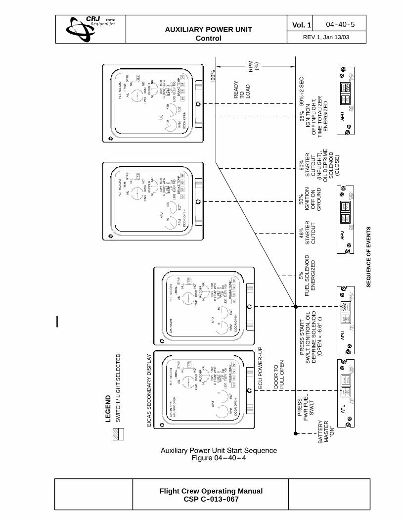
When the PWR FUEL switchlight, on the APU panel, is selected:
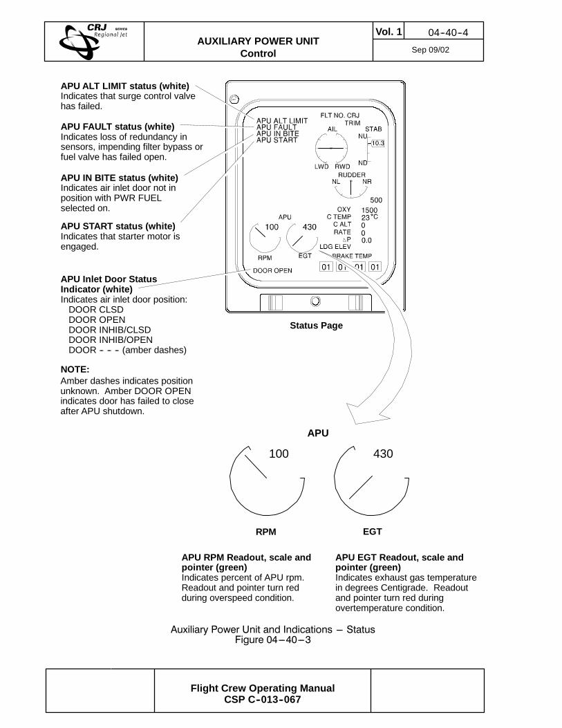
S The ECU is powered
S The air inlet door opens (position is displayed on the EICAS status page)
S The APU RPM and EGT gauges are displayed on the EICAS status page
S The fuel pump comes on
When the START/STOP switchlight, on the APU control panel, is selected:
S The ignition is activated
S The starter motor is energized
S The fuel shutoff valve opens
S The START legend on the APU panel comes on
S The APU START status message is displayed
The starter motor is deactivated at 46% rpm on the ground or at 60% rpm if in flight andthe START legend goes out. When the APU reaches 95% rpm, ignition is turned off.Two seconds after the APU reaches 99% rpm, the AVAIL legend, in the START/STOPswitchlight, illuminates to notify the crew that the APU is ready for loading.
B. Stopping
To shutdown the APU, the crew pushes the START/STOP switchlight on the APUpanel. The APU will automatically shed its loading and shutdown. The PWR/FUELswitch is deselected to close the fuel shutoff valve and to remove primary electricalpower to the ECU.
In the event of an emergency, the flight crew can press the APU FIRE PUSH switchlighton the glareshield. On the ground, the APU can be shut down by pushing an APUemergency stop button located in the APU compartment or by selecting an APUshut--off switch on the external services panel on the RH forward fuselage. Eitherselection sends a signal to the ECU to carry out an immediate shutdown.
04--40--2Vol. 1AUXILIARY POWER UNIT
Control REV 3, May 03/05
Flight Crew Operating ManualCSP C--013--067
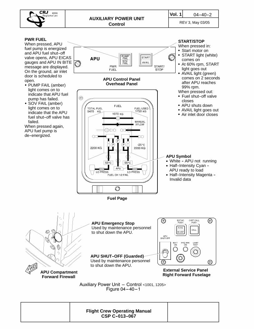
Auxiliary Power Unit --- Control <1001, 1205>Figure 04---40---1
APU Control PanelOverhead Panel
APU SHUT--OFF (Guarded)Used by maintenance personnelto shut down the APU.
External Service PanelRight Forward Fuselage
Fuel Page
APU SymbolWhite -- APU not runningHalf--Intensity Cyan --APU ready to loadHalf--Intensity Magenta --Invalid data
When pressed out:Fuel shut--off valveclosesAPU shuts downAVAIL light goes outAir inlet door closes
APU CompartmentForward Firewall
APU Emergency StopUsed by maintenance personnelto shut down the APU.
BRT
PWR FUELWhen pressed, APUfuel pump is energizedand APU fuel shut--offvalve opens, APU EICASgauges and APU IN BITEmessage are displayed.On the ground, air inletdoor is scheduled toopen.PUMP FAIL (amber)light comes on toindicate that APU fuelpump has failed.SOV FAIL (amber)light comes on toindicate that the APUfuel shut--off valve hasfailed.
When pressed again,APU fuel pump isde--energized.
04--40--3Vol. 1AUXILIARY POWER UNIT
Control Sep 09/02
Flight Crew Operating ManualCSP C--013--067
EICAS Auxiliary Power Unit Indications --- Primary Page <1001>Figure 04---40---2