58
CHAPTER 4 DESIGN OF CULVERTS 22 February 2000

CHAPTER 4
DESIGN OF CULVERTS
22 February 2000

Drainage Criteria Manual
Chapter Four - Design of Culverts
Table Of Contents4.1 Overview . . . . . . . . . . . . . . . . . . . . . . . . . . . . . . . . . . . . . . . . . . . . . . . . . . . . . . . . . . . . . . . . . . . . . . . . . . 4 - 1
4.1.1 Introduction . . . . . . . . . . . . . . . . . . . . . . . . . . . . . . . . . . . . . . . . . . . . . . . . . . . . . . . . . . . . . 4 - 14.1.2 Definition . . . . . . . . . . . . . . . . . . . . . . . . . . . . . . . . . . . . . . . . . . . . . . . . . . . . . . . . . . . . . . . 4 - 14.1.3 Purpose . . . . . . . . . . . . . . . . . . . . . . . . . . . . . . . . . . . . . . . . . . . . . . . . . . . . . . . . . . . . . . . . 4 - 14.1.4 Considerations . . . . . . . . . . . . . . . . . . . . . . . . . . . . . . . . . . . . . . . . . . . . . . . . . . . . . . . . . . . 4 - 14.1.5 Bridge or Culvert Selection . . . . . . . . . . . . . . . . . . . . . . . . . . . . . . . . . . . . . . . . . . . . . . . . . . 4 - 1
4.2 Symbols And Definitions . . . . . . . . . . . . . . . . . . . . . . . . . . . . . . . . . . . . . . . . . . . . . . . . . . . . . . . . . . . . . . 4 - 14.3 Concept Definitions . . . . . . . . . . . . . . . . . . . . . . . . . . . . . . . . . . . . . . . . . . . . . . . . . . . . . . . . . . . . . . . . . . 4 - 34.4 Culvert Design Steps . . . . . . . . . . . . . . . . . . . . . . . . . . . . . . . . . . . . . . . . . . . . . . . . . . . . . . . . . . . . . . . . . . 4 - 44.5 Engineering Design Criteria . . . . . . . . . . . . . . . . . . . . . . . . . . . . . . . . . . . . . . . . . . . . . . . . . . . . . . . . . . . . . 4 - 5
4.5.1 Criteria . . . . . . . . . . . . . . . . . . . . . . . . . . . . . . . . . . . . . . . . . . . . . . . . . . . . . . . . . . . . . . . . . 4 - 54.5.2 Flood Frequency . . . . . . . . . . . . . . . . . . . . . . . . . . . . . . . . . . . . . . . . . . . . . . . . . . . . . . . . . . 4 - 54.5.3 Velocity Limitations . . . . . . . . . . . . . . . . . . . . . . . . . . . . . . . . . . . . . . . . . . . . . . . . . . . . . . . . 4 - 64.5.4 Buoyancy Protection . . . . . . . . . . . . . . . . . . . . . . . . . . . . . . . . . . . . . . . . . . . . . . . . . . . . . . . 4 - 64.5.5 Length and Slope . . . . . . . . . . . . . . . . . . . . . . . . . . . . . . . . . . . . . . . . . . . . . . . . . . . . . . . . . . 4 - 64.5.6 Debris Control . . . . . . . . . . . . . . . . . . . . . . . . . . . . . . . . . . . . . . . . . . . . . . . . . . . . . . . . . . . . 4 - 64.5.7 Headwater Limitations . . . . . . . . . . . . . . . . . . . . . . . . . . . . . . . . . . . . . . . . . . . . . . . . . . . . . . 4 - 64.5.8 Tailwater Considerations . . . . . . . . . . . . . . . . . . . . . . . . . . . . . . . . . . . . . . . . . . . . . . . . . . . . 4 - 74.5.9 Freeboard . . . . . . . . . . . . . . . . . . . . . . . . . . . . . . . . . . . . . . . . . . . . . . . . . . . . . . . . . . . . . . . 4 - 74.5.10 Culvert Inlets . . . . . . . . . . . . . . . . . . . . . . . . . . . . . . . . . . . . . . . . . . . . . . . . . . . . . . . . . . . . . 4 - 74.5.11 Inlets With Headwalls . . . . . . . . . . . . . . . . . . . . . . . . . . . . . . . . . . . . . . . . . . . . . . . . . . . . . . . 4 - 84.5.12 Wingwalls And Aprons . . . . . . . . . . . . . . . . . . . . . . . . . . . . . . . . . . . . . . . . . . . . . . . . . . . . . 4 - 94.5.13 Improved Inlets . . . . . . . . . . . . . . . . . . . . . . . . . . . . . . . . . . . . . . . . . . . . . . . . . . . . . . . . . . . 4 - 94.5.14 Manning’s n Values . . . . . . . . . . . . . . . . . . . . . . . . . . . . . . . . . . . . . . . . . . . . . . . . . . . . . . . 4 - 114.5.15 Culvert Skews . . . . . . . . . . . . . . . . . . . . . . . . . . . . . . . . . . . . . . . . . . . . . . . . . . . . . . . . . . . 4 - 114.5.16 Minimum Culvert Size . . . . . . . . . . . . . . . . . . . . . . . . . . . . . . . . . . . . . . . . . . . . . . . . . . . . . 4 - 114.5.17 Outlet Protection . . . . . . . . . . . . . . . . . . . . . . . . . . . . . . . . . . . . . . . . . . . . . . . . . . . . . . . . . 4 - 114.5.18 Permitting Considerations . . . . . . . . . . . . . . . . . . . . . . . . . . . . . . . . . . . . . . . . . . . . . . . . . . 4 - 124.5.19 Safety Considerations . . . . . . . . . . . . . . . . . . . . . . . . . . . . . . . . . . . . . . . . . . . . . . . . 4 - 124.5.20 Loading Requirements . . . . . . . . . . . . . . . . . . . . . . . . . . . . . . . . . . . . . . . . . . . . . . . . 4 - 12
4.6 Culvert Flow Controls And Equations . . . . . . . . . . . . . . . . . . . . . . . . . . . . . . . . . . . . . . . . . . . . . . . . . . . . 4 - 124.6.1 Introduction . . . . . . . . . . . . . . . . . . . . . . . . . . . . . . . . . . . . . . . . . . . . . . . . . . . . . . . . . . . . 4 - 124.6.2 Inlet And Outlet Control . . . . . . . . . . . . . . . . . . . . . . . . . . . . . . . . . . . . . . . . . . . . . . . . . . . . 4 - 124.6.3 Equations . . . . . . . . . . . . . . . . . . . . . . . . . . . . . . . . . . . . . . . . . . . . . . . . . . . . . . . . . . . . . . 4 - 12
4.6.3.1 Mild Slope . . . . . . . . . . . . . . . . . . . . . . . . . . . . . . . . . . . . . . . . . . . . . . . . . . . . . . 4 - 134.6.3.2 Steep Slope . . . . . . . . . . . . . . . . . . . . . . . . . . . . . . . . . . . . . . . . . . . . . . . . . . . . . 4 - 144.6.3.3 Slug Flow . . . . . . . . . . . . . . . . . . . . . . . . . . . . . . . . . . . . . . . . . . . . . . . . . . . . . . . 4 - 14
4.7 Design Procedures . . . . . . . . . . . . . . . . . . . . . . . . . . . . . . . . . . . . . . . . . . . . . . . . . . . . . . . . . . . . . . . . . . 4 - 144.7.1 Procedures . . . . . . . . . . . . . . . . . . . . . . . . . . . . . . . . . . . . . . . . . . . . . . . . . . . . . . . . . . . . . 4 - 144.7.2 Tailwater Elevations . . . . . . . . . . . . . . . . . . . . . . . . . . . . . . . . . . . . . . . . . . . . . . . . . . . . . . . 4 - 144.7.3 Culvert Design Nomographs . . . . . . . . . . . . . . . . . . . . . . . . . . . . . . . . . . . . . . . . . . . . . . . . 4 - 154.7.4 Steps In The Design Procedure . . . . . . . . . . . . . . . . . . . . . . . . . . . . . . . . . . . . . . . . . . . . . . 4 - 154.7.5 Performance Curves . . . . . . . . . . . . . . . . . . . . . . . . . . . . . . . . . . . . . . . . . . . . . . . . . . . . . . 4 - 184.7.6 Roadway Overtopping . . . . . . . . . . . . . . . . . . . . . . . . . . . . . . . . . . . . . . . . . . . . . . . . . . . . . 4 - 184.7.7 Storage Routing . . . . . . . . . . . . . . . . . . . . . . . . . . . . . . . . . . . . . . . . . . . . . . . . . . . . . . . . . . 4 - 18

Drainage Criteria Manual
Chapter Four - Design of Culverts
Table Of Contents4.8 Culvert Design Example Using Nomographs . . . . . . . . . . . . . . . . . . . . . . . . . . . . . . . . . . . . . . . . . . . . . . . 4 - 204.9 Design of Improved Inlets . . . . . . . . . . . . . . . . . . . . . . . . . . . . . . . . . . . . . . . . . . . . . . . . . . . . . . . 4 - 23
4.9.1 Introduction . . . . . . . . . . . . . . . . . . . . . . . . . . . . . . . . . . . . . . . . . . . . . . . . . . . . . . . . . . . . . . . . . 4 - 234.9.2 Outlet Control . . . . . . . . . . . . . . . . . . . . . . . . . . . . . . . . . . . . . . . . . . . . . . . . . . . . . . . . . . . . . . . . 4 - 234.9.3 Inlet Control . . . . . . . . . . . . . . . . . . . . . . . . . . . . . . . . . . . . . . . . . . . . . . . . . . . . . . . . . . . . . . . . . 4 - 23
4.9.4 Common Entrances . . . . . . . . . . . . . . . . . . . . . . . . . . . . . . . . . . . . . . . . . . . . . . . . . . . . . . . . . . . . 4 - 23 4.9.5 Capacity Determinations . . . . . . . . . . . . . . . . . . . . . . . . . . . . . . . . . . . . . . . . . . . . . . . . . . . . . . . . . 4 - 23 4.9.6 Improved Inlets . . . . . . . . . . . . . . . . . . . . . . . . . . . . . . . . . . . . . . . . . . . . . . . . . . . . . . . . . . . . . . . 4 - 23
4.9.6.1 Bevel-Edged Inlet . . . . . . . . . . . . . . . . . . . . . . . . . . . . . . . . . . . . . . . . . . . . . . . . . . . . . . . . 4 - 244.9.6.2 Side-Tapered Inlet . . . . . . . . . . . . . . . . . . . . . . . . . . . . . . . . . . . . . . . . . . . . . . . . . . . . . . . . 4 - 244.9.6.3 Slope-Tapered Inlet . . . . . . . . . . . . . . . . . . . . . . . . . . . . . . . . . . . . . . . . . . . . . . . . . . . . . . . 4 - 244.9.6.4 Improved Inlet Performance . . . . . . . . . . . . . . . . . . . . . . . . . . . . . . . . . . . . . . . . . . . . . . . . . 4 - 25
4.10 Design Procedures For Beveled-Edged Inlets . . . . . . . . . . . . . . . . . . . . . . . . . . . . . . . . . . . . . . . . . . . . . . 4 - 254.10.1 Introduction . . . . . . . . . . . . . . . . . . . . . . . . . . . . . . . . . . . . . . . . . . . . . . . . . . . . . . . . . . . . . . . . 4 - 254.10.2 Design Figures . . . . . . . . . . . . . . . . . . . . . . . . . . . . . . . . . . . . . . . . . . . . . . . . . . . . . . . . . . . . . . 4 - 254.10.3 Design Procedure . . . . . . . . . . . . . . . . . . . . . . . . . . . . . . . . . . . . . . . . . . . . . . . . . . . . . . . . . . . . 4 - 264.10.4 Design Figure Limits . . . . . . . . . . . . . . . . . . . . . . . . . . . . . . . . . . . . . . . . . . . . . . . . . . . . . . . . . . 4 - 264.10.5 Area Ratios . . . . . . . . . . . . . . . . . . . . . . . . . . . . . . . . . . . . . . . . . . . . . . . . . . . . . . . . . . . . . . . . 4 - 264.10.6 Multibarrel Installations . . . . . . . . . . . . . . . . . . . . . . . . . . . . . . . . . . . . . . . . . . . . . . . . . . . . . . . . 4 - 264.10.7 Skewed Inlets . . . . . . . . . . . . . . . . . . . . . . . . . . . . . . . . . . . . . . . . . . . . . . . . . . . . . . . . . . . . . . . 4 - 26
4.11 HYDRAIN Culvert Computer Program . . . . . . . . . . . . . . . . . . . . . . . . . . . . . . . . . . . . . . . . . . . . . . . . . . 4 - 27 4.11.1 Introduction . . . . . . . . . . . . . . . . . . . . . . . . . . . . . . . . . . . . . . . . . . . . . . . . . . . . . . . . . . . . . . . . . . 4 - 27 4.11.2 User-Friendly Features . . . . . . . . . . . . . . . . . . . . . . . . . . . . . . . . . . . . . . . . . . . . . . . . . . . . . . . . . . 4 - 27 4.11.3 Examples . . . . . . . . . . . . . . . . . . . . . . . . . . . . . . . . . . . . . . . . . . . . . . . . . . . . . . . . . . . . . . . . . . . . 4 - 274.12 Construction And Maintenance Considerations . . . . . . . . . . . . . . . . . . . . . . . . . . . . . . . . . . . . . . . . . . . . 4 - 27References . . . . . . . . . . . . . . . . . . . . . . . . . . . . . . . . . . . . . . . . . . . . . . . . . . . . . . . . . . . . . . . . . . . . . . . . . . . . 4 - 28
APPENDICES
APPENDIX 4-A HY8 CULVERT ANALYSIS - MICROCOMPUTER PROGRAM 4-A, page 1APPENDIX 4-B CRITICAL DEPTH CHARTS 4-B, page 1APPENDIX 4-C IMPROVEMENT INLET FIGURES 4-C, page 1APPENDIX 4-D CULVERT DESIGN 4-D, page 1

Design of Culverts
4 - 1Drainage Criteria Manual
4.1 Overview
4.1.1 Introduction
The design of a culvert is influenced by cost, hydraulic efficiency, purpose, and the topography at the proposedculvert site. Thus physical data must be integrated with engineering and economic considerations. The informationcontained in this chapter should give the design engineer the ability to design culverts taking into account the factorsthat influence their design and selection.
4.1.2 Definition
Culverts are structures used to convey surface runoff through embankments. Culverts are usually covered withembankment and composed of structural material around the entire perimeter, although some are supported on spreadfootings with the streambed serving as the bottom of the culvert. For economy and hydraulic efficiency, culvertsshould be designed to operate with the inlet submerged during flood flows, if conditions permit. Cross-drains arethose culverts and pipes that are used to convey runoff from one side of a roadway to another. 4.1.3 Purpose
The primary purpose of a culvert is to convey surface water across or from the roadway right-of-way. In additionto the hydraulic function, a culvert must also support the embankment and roadway for traffic conveyance, and protectthe traveling public and adjacent property owners from flood hazards to the extent practicable and in a reasonableand prudent manner. 4.1.4 Considerations
Primary considerations for the final selection of any drainage structure are that its design be based upon appropriatehydraulic principles, economy, and minimized effects on adjacent property by the resultant headwater depth and outletvelocity. In addition to sound hydraulic design, sound structural design, site design, and construction practices arenecessary for a culvert to function properly. The allowable headwater elevation is that elevation above which damagemay be caused to adjacent property and/or the roadway. It is this allowable headwater depth that is the primary basisfor sizing a culvert.
To ensure safety during major flood events, access and egress routes to developed areas shall be checked for the100-year flood to determine if these streets will provide safe access for emergency vehicles and local residents. 4.1.5 Bridge or Culvert Selection
At many sites, either a bridge or a culvert will fulfill the structural and hydraulic requirements. The structuralchoice should be based on:
! risk of property damage,! construction and maintenance costs,! traffic safety,! environmental considerations,! risk of failure, and! aesthetic considerations.
4.2 Symbols And Definitions
To provide consistency within this chapter, as well as throughout this manual, the following symbols will be used.These symbols were selected because of their wide use in many culvert design publications.

Design of Culverts
4 - 2 Drainage Criteria Manual
Table 4-1 Symbols, Definitions And UnitsSymbol Definition Units
A Area of cross section of flow sq. ft B Barrel width ft Cd Overtopping discharge coefficient - D Culvert diameter or barrel depth in. or ft d Depth of flow ft dc Critical depth of flow ft du Uniform depth of flow ft g Acceleration of gravity ft/sH Total energy loss ft He Entrance head loss ft Hf Friction head loss ft ho Height of hydraulic grade line above outlet invert ft HW Headwater depth above invert of culvert (depth from
inlet invert to upstream total energy grade line) ft Ke Inlet loss coefficient - L Length of culvert ft P Empirical approximation of equivalent hydraulic grade line ft Q Rate of discharge cfs S Slope of culvert ft/fTW Tailwater depth above invert of culvert ft V Mean velocity of flow ft/sVc Critical velocity ft/s

Design of Culverts
4 - 3Drainage Criteria Manual
4.3 Concept Definitions
Critical Depth
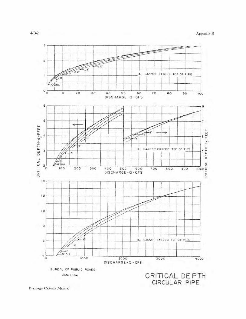
Critical depth can best be illustrated as the depth at which water flows over a weir, this depth being attained auto-matically where no other backwater forces are involved. For a given discharge and cross-section geometry thereis only one critical depth. Appendix B at the end of this chapter gives a series of critical depth charts for the differentculvert shapes.
Uniform Flow
Uniform flow is flow in a prismatic channel of constant cross section having a constant discharge, velocity anddepth of flow throughout the reach. This type of flow will exist in a culvert operating on a steep slope provided theculvert is sufficiently long.
Free Outlets
Free outlets are outlets whose tailwater is equal to or lower than critical depth. For culverts having free outlets,lowering of the tailwater has no effect on the discharge or the backwater profile upstream of the tailwater.
Submerged Outlets
Partially submerged outlets are outlets whose tailwater is higher than critical depth and lower than the height ofthe culvert. Submerged outlets are outlets having a tailwater elevation higher than the soffit of the culvert.
Submerged Inlets
Submerged inlets are those inlets having a headwater greater than about one and one-half times the diameter ofthe culvert.
Improved Inlets
Flared, improved, or tapered inlets indicate a special entrance condition which decreases the amount of energyneeded to pass the flow through the inlet and thus increases the capacity of culverts at the inlet.
Soffit
Soffit refers to the inside top of the culvert. The soffit is also referred to as the crown of the culvert.
Invert
Invert refers to the flowline of the culvert (inside bottom).
Steep and Mild Slope
A steep slope culvert operation is where the computed critical depth is greater than the computed uniform depth.A mild slope culvert operation is where critical depth is less than uniform depth.

Design of Culverts
4 - 4 Drainage Criteria Manual
4.4 Culvert Design Steps
Following are the recommended steps in the design of a culvert in order to ensure that all design aspects are takeninto account.
Step 1 Determine And Analyze Site Characteristics - Site characteristics include the generalized shape of theroadway embankment, bottom elevations and cross sections along the stream bed, the approximate lengthof the culvert, and the allowable headwater elevation. In determining the allowable headwater elevation,roadway elevations and the elevation of upstream property should be considered. The consequences ofexceeding the allowable headwater elevation should be evaluated and kept in mind throughout the designprocess.
Culvert design is actually a trial-and-error procedure because the length of the barrel cannot be accuratelydetermined until the size is known, and the size cannot be precisely determined until the length is known.In most cases, however, a reasonable estimate of length will be accurate enough to determine the culvertsize.
Step 2 Perform Hydrologic Analysis - Delineate the drainage area above the culvert site. Develop flow estimatesfor the design frequencies. Design frequencies are discussed in Section 4.5.2. The probable accuracy ofthe estimate should be kept in mind as the design proceeds.
Step 3 Perform Outlet Control Calculations And Select Culvert - These calculations are performed before inletcontrol calculations in order to select the smallest feasible barrel which can be used without the requiredheadwater elevation in outlet control exceeding the allowable headwater elevation. The full flow outletcontrol performance curve for a given culvert (size, inlet edge, shape, material) defines its maximumperformance. Therefore, the inlet improvements beyond the beveled edge or changes in inlet invert elevationwill not reduce the required outlet control headwater elevation. This makes the outlet control performancecurve an ideal limit for improved inlet design. The results of these calculations should be the outlet controlperformance curve. In addition to considering the allowable headwater elevation, the velocity of flow atthe exit to the culvert should be checked to determine if downstream erosion problems will be created.
Step 4 Perform Inlet Control Calculations For Conventional And Beveled Edge Culvert Inlets - Perform the inletcontrol calculations to develop the inlet control performance curve to determine if the culvert design selectedwill be on inlet or outlet control for the design and check flood frequencies. A drop may be incorporatedupstream of the culvert to increase the flow through the culvert.
Step 5 Perform Throat Control Calculations For Side- And Slope-Tapered Inlets - The same concepts are involvedhere as with conventional or beveled edge culvert design.
Step 6 Analyze The Effect of a Drop On Inlet Control Section Performance -The purpose of this step is to determineif having a drop before the inlet of the culvert would increase the capacity of the culvert and if a drop canbe justified from a cost perspective and site characteristics.
Step 7 Design Side- And/Or Slope-Tapered Inlet - Side- and slope-tapered inlets can be used to significantlyincrease the capacity of many culvert designs. Develop performance curves based on side- and/or slope-tapered inlets and determine from a cost perspective and site characteristics if such a design would bejustified.
Step 8 Complete File Documentation - Complete a documentation file for the final design selected.

Design of Culverts
4 - 5Drainage Criteria Manual
4.5 Engineering Design Criteria
4.5.1 Criteria
The design of a culvert should take into account many different engineering and technical aspects at the culvertsite and adjacent areas. The following design criteria should be considered for all culvert designs as applicable.
Engineering aspects ! Flood frequency! Velocity limitation! Buoyancy protection
Site criteria ! Length and slope! Debris control
Design limitations ! Headwater! Tailwater conditions! Storage
Design options ! Culvert inlets! Inlets with headwalls! Wingwalls and aprons! Improved inlets! Material selection! Culvert skews! Culvert sizes
Related designs ! Weep holes! Outlet protection! Erosion and sediment control! Environmental considerations! Safety considerations! Loading requirements
Some culvert designs are relatively simple, involving a straight-forward determination of culvert size and length.Other designs are more complex where structural, hydraulic, environmental, or other considerations must be evaluatedand provided for in the final design. The design engineer must incorporate personal experience and judgment todetermine which criteria must be evaluated and how to design the final culvert installation.
Following is a discussion of each of the above criteria as it relates to culvert siting and design.
4.5.2 Flood Frequency
Culverts shall be designed to convey (at a minimum) the 50-year runoff event without overtopping the roadway.The flow rate shall be based on upstream full-buildout land-use conditions from the City of Lincoln/Lancaster Countycomprehensive plan. Where roadside ditches convey the minor storm drainage in lieu of storm sewers, appurtenantculverts shall be designed to convey the 10-year storm event, but in no case shall be less than the minimum sizesspecified in Section 4.5.16 of this chapter.
In addition, the 100-year frequency storm shall be routed through all culverts to be sure structures are not floodedor increased damage does not occur to the roadway or adjacent property for this design event.
An economic analysis may justify a design to pass floods greater than those noted above where potential damageto adjacent property, to human life, or heavy financial loss due to flooding is significant. Also, in compliance with the National Flood Insurance Program, it is necessary to consider the 100-year frequencyflood at locations identified as being special flood hazard areas. This does not necessitate that the culvert be sizedto pass the 100-year flood, provided the capacity of the culvert plus flow by-passing the culvert, is sufficient toaccommodate the 100-year flood without raising the associated water surface elevation more than floodplainregulations or adjacent property elevations allow for that location. In addition, stormwater management facilitiescannot be installed which would result in a major lowering of the associated water surface elevation without adownstream evaluation. The design engineer should review the City floodway regulations for more informationrelated to floodplain regulations.

Design of Culverts
4 - 6 Drainage Criteria Manual
4.5.3 Velocity Limitations
Both minimum and maximum velocities should be considered when designing a culvert. The maximum velocityshould not exceed culvert manufacturer recommendations. The maximum velocity should be consistent with channelstability requirements at the culvert outlet. As outlet velocities increase, the need for channel stabilization at theculvert outlet increases. If velocities exceed permissible velocities for the various types of nonstructural outlet liningmaterial available, the installation of structural energy dissipators is appropriate.
A minimum velocity of 3.0 ft/s when the culvert is flowing partially full is recommended to ensure a self-cleaningcondition during partial depth flow. Energy dissipation may be required at the outlet of the culvert (see Chapter 7). 4.5.4 Buoyancy Protection
Headwalls, endwalls, slope paving or other means of anchoring to provide buoyancy protection should beconsidered for all flexible culverts. Buoyancy is more serious with steepness of the culvert slope, depth of thepotential headwater (debris blockage may increase), flatness of the upstream fill slope, height of the fill, large culvertskews, or mitered ends.
4.5.5 Length and Slope
Since the capacity of culverts on outlet control will be affected by the length of the culvert, their length shouldbe kept to a minimum and existing facilities shall not be extended without determining the decrease in capacity thatwill occur. In addition, the culvert length and slope should be chosen to approximate existing topography. To thedegree practicable, the culvert invert should be aligned with the channel bottom and the skew angle of the stream,and the culvert entrance should match the geometry of the roadway embankment.
4.5.6 Debris Control
The need for bar grates should be considered for each culvert site, but in general, bar grates shall not be used onend sections for culverts (either inlets or outlets) unless approved by the Director of Public Works and Utilities. 4.5.7 Headwater Limitations
The allowable headwater elevation is determined from an evaluation of land use upstream of the culvert and theproposed roadway elevation. Headwater is the depth of water above the culvert invert measured at the entrance endof the culvert.
The following criteria related to headwater should be considered:
! The allowable headwater for design frequency conditions should allow for the following upstream controls:12 inch freeboard.Avoidance of upstream property damage.Elevations established to delineate floodplain zoning.Low point in the road grade either adjacent to or away from the culvert location.Ditch elevation of the terrain that would permit flow to divert around culvert.
! The headwater shall be checked for the 100-year flood to ensure compliance with floodplain managementcriteria and to avoid flooding of building sites. For most facilities, the culvert should be sized to maintainflood-free conditions on major thoroughfares for one-half lane of two-lane facilities and one lane of multi-lanefacilities.
! The maximum acceptable outlet velocity shall be identified. Either the headwater shall be set to produceacceptable velocities or stabilization measures shall be provided where these velocities are exceeded.
! Site-specific design considerations shall be addressed.! In general the constraint which gives the lowest allowable headwater elevation establishes the criteria for
the hydraulic calculations.
Invert elevations will be established after determining the allowable headwater elevation, tailwater elevation, andapproximate length. Scour can be minimized if the culvert has the same slope as the channel. Thus, to reduce thechance of failure due to scour, invert elevations should correspond to the natural grade where feasible. In addition,the flow conditions and velocity in the channel upstream from the culvert should be investigated to determine if scourwill occur.
If there is insufficient headwater elevation to convey the required discharge, it will be necessary to either use a

Design of Culverts
4 - 7Drainage Criteria Manual
larger culvert, lower the inlet invert, use an irregular cross section, use an improved inlet if in inlet control, usemultiple barrels or a bridge, or use a combination of these measures. If the inlet invert is lowered, special consider-ation must be given to scour.
4.5.8 Tailwater Considerations
The hydraulic conditions downstream of the culvert site must be evaluated to determine a tailwater depth for arange of discharge. At times there may be a need for calculating backwater curves to establish the tailwater condi-tions. If the culvert outlet is operating with a free outfall, the critical depth and equivalent hydraulic grade line shouldbe determined.
For culverts which discharge to an open channel, the stage-discharge curve for the channel must be determined.(See Chapter 5.)
If an upstream culvert outlet is located near a downstream culvert inlet, the headwater elevation of the downstreamculvert may establish the design tailwater depth for the upstream culvert.
If the culvert discharges to a lake, pond, or other major water body, the expected high water elevation of theparticular water body may establish the culvert tailwater. 4.5.9 Freeboard
In the design of cross drainage culverts, there shall be a minimum of a one-foot freeboard between the floodelevation and the roadway surface for all floods that are equal to or less than the design flood event. In addition, thereshall be a minimum of one-foot freeboard between the headwater elevation for a culvert under 100-year storm eventflow or by-pass conditions and the low opening of upstream or adjacent building sites.
4.5.10 Culvert Inlets
Selection of the type of inlet is an important part of culvert design, particularly with inlet control. Hydraulicefficiency and cost can be significantly affected by inlet conditions.
The inlet coefficient Ke, is a measure of the hydraulic efficiency of the inlet, with lower values indicating greaterefficiency. All methods described in this chapter, directly or indirectly, use inlet coefficients. Recommended inletcoefficients are given in Table 4-2.

Design of Culverts
4 - 8 Drainage Criteria Manual
Table 4-2 Inlet Coefficients
Type of Structure and Design of Entrance Coefficient Ke
Pipe, ConcreteProjecting from fill, socket end (grove-end) 0.2 Projecting from fill, square cut end 0.5Headwall or headwall and wingwalls
Socket end of pipe (groove-end) 0.2Square-edge 0.5Rounded [radius = 1/12(D)] 0.2
Mitered to conform to fill slope 0.7*End-Section conforming to fill slope 0.5Beveled edges, 33.7o or 45o bevels 0.2Side- or slope-tapered inlet 0.2
Pipe, or Pipe-Arch, Corrugated MetalProjecting from fill (no headwall) 0.9Headwall or headwall and wingwalls square-edge 0.5Mitered to fill slope, paved or unpaved slope 0.7*End-Section conforming to fill slope 0.5Beveled edges, 33.7o or 45o bevels 0.2Side- or slope-tapered inlet 0.2
Box, Reinforced ConcreteHeadwall parallel to embankment (no wingwalls)
Square-edged on 3 edges 0.5Rounded on 3 edges to radius of [1/12(D)] or beveled edges on 3 sides 0.2
Wingwalls at 30o to 75o to barrelSquare-edged at crown 0.4Crown edge rounded to radius of [1/12(D)] or beveled top edge 0.2
Wingwalls at 10o or 25o to barrelSquare-edged at crown 0.5
Wingwalls parallel (extension of sides)Square-edged at crown 0.7
Side- or slope-tapered inlet 0.2
* Note: End Sections conforming to fill slope, made of either metal or concrete, are the sections commonlyavailable from manufacturers. From limited hydraulic tests they are equivalent in operation to a headwall in bothinlet and outlet control. Some end sections incorporating a closed taper in their design have a superior hydraulicperformance. Source: HDS:5
4.5.11 Inlets With Headwalls
Headwalls may be used for a variety of reasons:
(1) increasing the efficiency of the inlet (2) providing embankment stability (3) providing embankment protection against erosion(4) providing protection from buoyancy or(5) to shorten the length of the required structure.
The primary reasons for using headwalls are for embankment protection, buoyancy control, and ease of mainten-ance. Figure 4-1 shows typical headwall and wingwall configurations. Culvert or storm sewer headwalls constructedin or adjacent to public right-of-way shall be designed to protect pedestrians. This protection shall include a pipe

Design of Culverts
4 - 9Drainage Criteria Manual
railing fence on the headwall and any wingwalls, unless the grading and size of the pipe precludes the need for thefence, as approved by the Director of Public Works and Utilities.
4.5.12 Wingwalls And Aprons
Wingwalls are used where the side slopes of the channel adjacent to the entrance are unstable or where the culvertis skewed to the normal channel flow.
Little increase in hydraulic efficiency is realized with the use of wingwalls, regardless of the pipe material usedand, therefore, the use should be justified for other reasons. Wingwalls can be used to increase hydraulic efficiencyif designed as a side-tapered inlet (See Section 4.9.6.2 for more information on the design of side-tapered inlets.)
If high headwater depths are to be encountered, or the approach velocity in the channel will cause scour, a shortchannel apron should be provided at the toe of the headwall. This apron should extend at least one pipe diameterupstream from the entrance, and the top of the apron should not protrude above the normal streambed elevation. 4.5.13 Improved Inlets
Where inlet conditions control the amount of flow that can pass through the culvert, improved inlets can greatlyincrease the hydraulic performance at the culvert. For these designs refer to the section 4.9 which describes the designof improved inlets.

Design of Culverts
4 - 10 Drainage Criteria Manual
Figure 4-1Typical Headwall and Wingwall Configurations
Source: Wright-McLaughlin Engineers

Design of Culverts
4 - 11Drainage Criteria Manual
4.5.14 Manning’s n Values
For culvert selection, only reinforced concrete pipe is allowed within City street right-of-way except for drivewayculverts. For culverts equal to or greater than 60 inches in diameter, corrugated metal pipe is allowed if it isbituminous coated with a concrete-poured invert. Table 4-3 gives recommended Manning's n values.
Table 4-3 Manning's n Values
Type of Conduit Wall & Joint Description Manning's n
Concrete Pipe Good joints, smooth walls 0.011-0.013Good joints, rough walls 0.014-0.016Poor joints, rough walls 0.016-0.017
Concrete Box Good joints, smooth finished walls 0.014-0.018Poor joints, rough, unfinished walls 0.014-0.018
Corrugated 2 2/3 by 1/2-inch corrugations 0.027-0.022Metal Pipes and 6 by 1-inch corrugations 0.025-0.022Boxes, Annular 5 by 1-inch corrugations 0.026-0.025Corrugations 3 by 1-inch corrugations 0.028-0.027
6 by 2-inch structural plate 0.035-0.0339 by 2 1/2-inch structural plate 0.037-0.033
Corrugated 2 2/3 by 1/2-inch corrugatedMetal Pipes, 24-inch plate width 0.024-0.012
Helical Corrugations, Full Circular FlowSpiral Rib Metal Pipe 3/4 by 3/4-inch recesses at 12-inch spacing, good joints 0.012-0.013
Note: For further information concerning Manning n values for selected conduits, consult Hydraulic Designof Highway Culverts, Federal Highway Administration, HDS No. 5, page 163.
4.5.15 Culvert Skews
Culvert skews shall not exceed 45 degrees as measured from a line perpendicular to the roadway centerlinewithout approval of the Director of Public Works and Utilities. 4.5.16 Minimum Culvert Size
The minimum culvert size shall be 18 inches for roadways and 15 inches for driveways. 4.5.17 Outlet Protection
See Chapter 7 for information on the design of outlet protection. In general, scour holes at culvert outletsprovide efficient energy dissipation. As such, outlet protection for the culvert should be provided where theoutlet scour hole depth computations indicate:
! the scour hole will undermine the culvert outlet,! the expected scour hole may cause costly property damage,! the scour hole will cause a nuisance effect (most common in urban areas), or! the scour hole will conflict with land use.

Design of Culverts
4 - 12 Drainage Criteria Manual
4.5.18 Permitting Considerations
There may be federal or state permitting implications that affect the culvert design. These could include wetlands,regulatory floodplains and preparation of a stormwater pollution prevention plan for construction activity.
4.5.19 Safety Considerations
Traffic should be protected from culvert ends as follows.
! Small culverts should use an end section or a sloped headwall.! Large culverts should receive one of the following treatments:
a. Be extended to the appropriate "clear zone" distance per AASHTO Roadside Design Guide.b. Shielded with a traffic barrier if the culvert is very large, cannot be extended, or has a channel which cannot
be safely traversed by a vehicle.! Routinely inspect each site to determine if safety problems exist for traffic or for the structural safety of the
culvert and embankment.
4.5.20 Loading Requirements
Reinforced concrete box culverts, reinforced concrete pipe culverts, and corrugated metal pipe culverts shall allbe designed for HS20 live load, with the appropriate impact factor, and dead load. Dead load (fill) shall be basedon the depth of earth cover, plus pavement, above the top of the culvert.
4.6 Culvert Flow Controls And Equations 4.6.1 Introduction
Generally, the hydraulic control in a culvert will be at the culvert outlet if the culvert is operating on a mild slope.Entrance control usually occurs if the culvert is operating on a steep slope.
For outlet control, the head losses due to tailwater and barrel friction are predominant in controlling the headwaterof the culvert. The entrance will allow the water to enter the culvert faster than the backwater effects of the tailwaterand barrel friction will allow it to flow through the culvert.
For inlet control, the entrance characteristics of the culvert are such that the entrance head losses are predominantin determining the headwater of the culvert. The barrel will carry water through the culvert more efficiently thanthe water can enter the culvert.
The design procedures contained in this chapter are for the design of culverts for a constant discharge, consideringinlet and outlet control. 4.6.2 Inlet And Outlet Control
Inlet Control - If the culvert is operating on a steep slope it is likely that the entrance geometry will control theheadwater and the culvert will be on inlet control.
Outlet Control - If the culvert is operating on a mild slope, the outlet characteristics will probably control the flowand the culvert will be on outlet control.
Proper culvert design and analysis requires checking for both inlet and outlet control to determine which willgovern particular culvert designs. For more information on inlet and outlet control see the Federal Highway Adminis-tration publication entitled Hydraulic Design Of Highway Culverts, HDS-5, 1985.
4.6.3 Equations
There are many combinations of conditions which classify a particular culvert's hydraulic operation. Byconsideration of a succession of parameters; the engineer may arrive at the appropriate calculation procedure. Themost common types of culvert operations for any barrel type are classified as follows.

Design of Culverts
4 - 13Drainage Criteria Manual
4.6.3.1 Mild Slope
Critical Depth - Outlet Control - The entrance is unsubmerged (HW < 1.5D), the critical depth is less than uniformdepth at the design discharge (dc < du) and the tailwater is less than or equal to critical depth (TW < dc). Thiscondition is a common occurrence where the natural channels are on flat grades and have wide, flat floodplains. Thecontrol is critical depth at the outlet.
HW = dc + Vc2/(2g) + He + Hf - SL (4.1)
Where: HW = headwater depth (ft)dc = critical depth (ft)Vc = critical velocityg = 32.2 (ft/sec2)He = entrance headloss (ft)
Hf = friction headloss (ft)S = slope of culvert (ft/ft)L = length of culvert (ft)
Tailwater Depth - Outlet Control - The entrance is unsubmerged (HW < 1.5D), the critical depth is less thanuniform depth at design discharge (dc < du) and TW is greater than critical depth (TW > dc) and TW is less than D(TW < D). This condition is a common occurrence where the channel is deep, narrow, and well defined. The controlis tailwater at the culvert outlet. The outlet velocity is the discharge divided by the area of flow in the culvert attailwater depth.
HW = TW + V2/(2g) + He + Hf - SL (4.2)
Where: HW = headwater depth (ft)TW = tailwater at the outlet (ft)V = velocity based on tailwater depth (ft)g = 32.2 (ft/sec2)He = entrance headloss (ft)Hf = friction headloss (ft)S = slope of culvert (ft/ft)L = length of culvert (ft)
Tailwater Depth > Barrel Depth - Outlet Control - This condition will exist if the critical depth is less than uniformdepth at the design discharge (dc < du) and TW depth is greater than D (TW > D), or; the critical depth is greater thanthe uniform depth at the design discharge (dc > du) and TW is greater than (SL + D), [TW > (SL + D)]. The HWmay or may not be greater than 1.5D, though often it is greater. If the critical depth of flow is determined to be greaterthan the barrel depth (only possible for rectangular culvert barrels), then this operation will govern. Outlet velocityis based on full flow at the outlet.
HW = H + TW - SL (4.3)
Where: HW = headwater depth (ft)H = total head loss of discharge through culvert (ft)TW = tailwater depth (ft)SL = culvert slope times length of culvert (ft)
Tailwater Depth < Barrel Depth - Outlet Control - The entrance is submerged (HW > 1.5D) and the tailwater depthis less than D (TW < D). Normally, the engineer should arrive at this type of operation only after previous considera-tion of the operations depth covered when the critical depth, tailwater depth, or "slug" flow controls the flow in outletcontrol conditions. On occasion, it may be found that (HW > 1.5D) for the three previously outlined conditions but(HW < 1.5D) for equation 4.4. If so, the higher HW should be used. Outlet velocity is based on critical depth ifTW depth is less than critical depth. If TW depth is greater than critical depth, outlet velocity is based on TW depth.

Design of Culverts
4 - 14 Drainage Criteria Manual
HW = H + P - SL (4.4)
Where: HW = headwater depth (ft)H = total head loss of discharge through culvert (ft)P = empirical approximation of equivalent hydraulic grade line (ft)P = (dc + D)/2 if TW depth is less than critical depth at design discharge. If TW is greater than
critical depth, then P = TW. (ft)SL = culvert slope times length of culvert (ft)
4.6.3.2 Steep Slope
Tailwater Insignificant - Inlet Control - The entrance may be submerged or unsubmerged, the critical depth isgreater than uniform depth at the design discharge (dc > du), TW depth is less than SL (tailwater elevation is lowerthan the upstream flowline). Tailwater depth with respect to the diameter of the culvert is inconsequential as longas the above conditions are met. This condition is a common occurrence for culverts in rolling or hilly country. Thecontrol is critical depth at the entrance for HW values up to about 1.5D. Control is the entrance geometry for HWvalues over about 1.5D. HW is determined from empirical curves in the form of nomographs that are discussed laterin this chapter. If TW is greater than D, outlet velocity is based on full flow at the outlet. If TW is less than D, outletvelocity is based on uniform depth for the culvert.
4.6.3.3 Slug Flow
Inlet or Outlet Control - For "slug" flow operation the entrance may be submerged or unsubmerged, critical depthis greater than uniform depth at the design discharge (dc > du), TW depth is greater than (SL + dc) (TW elevation isabove the critical depth at the entrance), and TW depth is less than SL + D (TW elevation is below the upstreamsoffit). TW depth with respect to D alone is inconsequential as long as the above conditions are met. This conditionis a common occurrence for culverts in rolling or hilly country. The control for this type of operation may be at theentrance or the outlet, or control may transfer itself back and forth between the two (commonly called "slug" flow).For this reason, it is recommended that HW be determined for both entrance control and outlet control and the higherof the two determinations be used. Entrance control HW is determined from the inlet control nomographs and outletcontrol HW is determined by equations 4.3, 4.4, or the outlet control nomographs.
If TW depth is less than D, outlet velocity should be based on TW depth. If TW depth is greater than D, outletvelocity should be based on full flow at the outlet.
4.7 Design Procedures
4.7.1 Procedures
There are two procedures for designing culverts described in this chapter: (1) the manual use of inlet and outletcontrol nomographs and (2) the use of a personal computer system HYDRAIN.
It is recommended that the HYDRAIN computer model be used for culvert design since it will allow the engineerto easily develop performance curves to examine more than one design situation. The personal computer systemHYDRAIN uses the theoretical basis for the nomographs to size a culvert. In addition, this system can evaluateimproved inlets, route hydrographs, consider road overtopping, and evaluate outlet streambed scour. By using watersurface profiles, this procedure is more accurate in predicting backwater effects and outlet scour.
The following will outline the design procedures for use of the nomograph. The use of the computer model willfollow the discussion on flood routing and culvert design. Other computer programs can be used if approved by theCity. 4.7.2 Tailwater Elevations
In some cases, culverts fail to perform as intended because of tailwater elevations high enough to create backwater.The problem is more severe in areas where gradients are very flat, and in some cases in areas with moderate slopes.Thus, as part of the design process, the normal depth of flow in the downstream channel at discharges equal to thosebeing considered should be computed.
If the tailwater computation leads to water surface elevations below the invert of the culvert exit, there areobviously no problems; if elevations above the culvert invert are computed, the culvert capacity will be somewhatless than assumed. The tailwater computation can be simple, and on steep slopes requires little more than the deter-

Design of Culverts
4 - 15Drainage Criteria Manual
mination of a cross section downstream where normal flow can be assumed, and a Manning equation calculation.(See Chapter 5 for more information on open channel analysis.) Conversely, with sensitive flood hazard sites, if theslopes are flat, or natural and man-made obstructions exist downstream, a water surface profile analysis reachingbeyond these obstructions may be required. 4.7.3 Culvert Design Nomographs
The use of culvert design nomographs requires a trial and error solution. The solution provides reliable designsfor many applications. It should be remembered that velocity, hydrograph routing, roadway overtopping, and outletscour require additional, separate computations beyond what can be obtained from the nomographs.
Figures 4-2 and 4-3 show examples of an inlet control and outlet control nomograph that can be used to designconcrete pipe culverts. For culvert designs not covered by these nomographs, refer to the complete set of nomographsgiven in Appendix D at the end of this chapter. 4.7.4 Steps In The Design Procedure
The design procedure requires the use of inlet and outlet nomographs.
Step Action(1) List design data:
Q = discharge (cfs) L = culvert length (ft)
S = culvert slope (ft/ft)HW = allowable headwater depth for the design storm (ft)V = velocity for trial diameter (ft/s)Ke = inlet loss coefficientTW = tailwater depth (ft)
(2) Determine trial culvert size by assuming a trial velocity 3 to 5 ft/s and computing the culvert area, A =Q/V. Determine the culvert diameter (inches).
(3) Find the actual HW for the trial size culvert for both inlet and outlet control.
! For inlet control, enter inlet control nomograph with D and Q and find HW/D for the proper entrancetype.
! Compute HW and, if too large or too small, try another culvert size before computing HW for outletcontrol.
! For outlet control, enter the outlet control nomograph with the culvert length, entrance loss coefficient,and trial culvert diameter.
! To compute HW, connect the length scale for the type of entrance condition and culvert diameter scalewith a straight line, pivot on the turning line, and draw a straight line from the design dischargethrough the turning point to the head loss scale H. Compute the headwater elevation HW from theequation:
HW = H + ho - LS (4.5)
Where: ho = 1/2 (critical depth + D), or tailwater depth, whichever is greater.

Design of Culverts
4 - 16 Drainage Criteria Manual
Figure 4-2

Design of Culverts
4 - 17Drainage Criteria Manual
Figure 4-3

Design of Culverts
4 - 18 Drainage Criteria Manual
(4) Compare the computed headwaters and use the higher HW to determine if the culvert is under inlet oroutlet control.
If outlet control governs and the HW is unacceptable, select a larger trial size and find another HW withthe outlet control nomographs. Since the smaller size of culvert had been selected for allowable HW bythe inlet control nomographs, the inlet control for the larger pipe need not be checked.
(5) Calculate exit velocity and expected streambed scour to determine if an energy dissipator is needed. 4.7.5 Performance Curves
A performance curve for any culvert can be obtained from the nomographs by repeating the steps outlined abovefor a range of discharges that are of interest for that particular culvert design. A graph is then plotted of headwatervs. discharge with sufficient points so that a curve can be drawn through the range of interest. These curves are appli-cable through a range of headwater, velocities, and scour depths versus discharges for a length and type of culvert.Usually charts with length intervals of 25 to 50 feet are satisfactory for design purposes. Such computations are mademuch easier by the computer program discussed in section 4.11 of this manual. 4.7.6 Roadway Overtopping
To complete the culvert design, roadway overtopping should be analyzed. A performance curve showing theculvert flow as well as the flow across the roadway is a useful analysis tool. Rather than using a trial and errorprocedure to determine the flow division between the overtopping flow and the culvert flow, an overall performancecurve can be developed.
The overall performance curve can be determined as follows:
Step Action
(1) Select a range of flow rates and determine the corresponding headwater elevations for the culvert flowalone. The flow rates should fall above and below the design discharge and cover the entire flow rangeof interest. Both inlet and outlet control headwaters should be calculated.
(2) Combine the inlet and outlet control performance curves to define a single performance curve for theculvert.
(3) When the culvert headwater elevations exceed the roadway crest elevation, overtopping will begin.Calculate the equivalent upstream water surface depth above the roadway (crest of weir) for each selectedflow rate. Use these water surface depths and equation 4.6 to calculate flow rates across the roadway.
Q = CdL(HW)1.5 (4.6)
Where: Q = overtopping flow rate (ft3/s)Cd = overtopping discharge coefficientL = length of roadway (ft)HW = upstream depth, measured from the roadway crest to the water surface upstream of the
weir drawdown (ft)
Note: See Figure 4-4 for guidance in determining a value for Cd. For more information on calculatingovertopping flow rates see pages 39 - 42 in HDS No. 5.
(4) Add the culvert flow and the roadway overtopping flow at the corresponding headwater elevations toobtain the overall culvert performance curve.
4.7.7 Storage Routing
A significant storage capacity behind a roadway embankment attenuates a flood hydrograph. Because of thereduction of the peak discharge associated with this attenuation, the required capacity of the culvert, and its size,may be reduced. If significant storage is anticipated behind a culvert, the design may be checked by routing thedesign hydrographs through the culvert to determine the discharge and stage behind the culvert. Routing proceduresare outlined in Hydraulic Design of Highway Culverts, Section V - Storage Routing, HDS No. 5, Federal Highway

Design of Culverts
4 - 19Drainage Criteria Manual
Administration. If storage routing is performed for a culvert, the facility should be designed as a detention pond andthe area inundated by floodwater should not be encroached upon.
Figure 4-4Discharge Coefficients For Roadway Overtopping

Design of Culverts
4 - 20 Drainage Criteria Manual
4.8 Culvert Design Example Using Nomographs
The following example problem illustrates the procedures to be used in designing culverts using the nomographs. Size a culvert given the following design conditions which were determined by physical limitations at the culvertsite and hydraulic procedures described elsewhere in this handbook. Input Data
Discharge for 50-yr flood = 70 cfsDischarge for 100-yr flood = 176 cfsAllowable HW for 10-yr discharge = 4.5 ftAllowable HW for 100-yr discharge = 7.0 ftLength of culvert = 100 ftNatural channel invert elevations - inlet = 15.50 ft
outlet = 15.35 ftCulvert slope = 0.0015 ft/ftTailwater depth for 50-yr discharge = 3.0 ftTailwater depth for 100-yr discharge = 4.0 ftTailwater depth is the normal depth in downstream channelEntrance type = Groove end with headwallCulvert type = Reinforced concrete
Computations
1. Assume a culvert velocity of 5 ft/s.
Required flow area = 70 cfs/5 ft/s = 14 sq ft (for the 50-yr recurrence flood).
2. The corresponding culvert diameter is about 48 in.
This can be calculated by using the formula for area of a circle:
Area = (3.14D2)/4 or D = (Area x 4/3.14)0.5
Therefore: D = ((14 sq ft x 4)/3.14)0.5 x 12 in./ft
D = 50.7 in.
3. A grooved end culvert with a headwall is selected for the design. Using the inlet control nomograph(Figure 4-2), with a pipe diameter of 48 in. and a discharge of 70 cfs; read a HW/D value of 0.93.
4. The depth of headwater (HW) is (0.93) x (4) = 3.72 ft which is less than the allowable headwaterof 4.5 ft.
5. The culvert is checked for outlet control by using Figure 4-3.
With an entrance loss coefficient Ke of 0.20 (see Table 4-2), a culvert length of 100 ft, and a pipediameter of 48 in., an H value of 0.77 ft is determined. The headwater for outlet control is computedby the equation:
HW = H + ho - LS
For the tailwater depth lower than the top of culvert,
ho = TW or 1/2 (critical depth in culvert + D) whichever is greater.ho = 3.0 ft or ho = 1/2 (2.55 + 4.0) = 3.28 ft

Design of Culverts
4 - 21Drainage Criteria Manual
The headwater depth for outlet control is:
HW = H + ho - LS = 0.77 + 3.28 - (100) x (0.0015) = 3.90 ft
6. Since HW for outlet control (3.90 ft) is greater than the HW for inlet control (3.72 ft), outlet controlgoverns the culvert design.
Thus, the maximum headwater expected for a 50-yr recurrence flood is 3.90 ft, which is less thanthe allowable headwater of 4.5 ft.
7. The performance of the culvert is checked for the 100-yr discharge.
The allowable headwater for a 100-yr discharge is 7 ft; critical depth in the 48 in. diameter culvertfor the 100-yr discharge is 3.96 ft.
For outlet control, an H of 4.6 is read from the outlet control nomograph. The maximum headwateris:
HW = H + ho - LS = 4.6 + 4.0 - (100) x (0.0015) = 8.45 ft
This depth is greater than the allowable depth of 7 ft, thus a larger size culvert must be selected.
8. A 54 in. diameter culvert is tried and found to have a maximum headwater depth of 3.74 ft for the10-yr discharge and a maximum headwater depth of 6.97 ft for the 100-yr discharge. These valuesare acceptable for the design conditions.
9. Estimate outlet exit velocity. Since this culvert is on outlet control and discharges into an openchannel downstream, the culvert will be flowing full at the flow depth in the channel. Using the100-year design peak discharge of 176 cfs and the area of a 54 in. or 4.5 ft diameter culvert, the exitvelocity will be:
V = Q/A = 176 / (3.14 (4.5)2)/4 = 11.1 ft/s
With this high velocity, some energy dissipator is needed downstream from this culvert for stream-bank protection. It will first be necessary to compute a scour hole depth and then decide whatprotection is needed. See Chapter 7, Energy Dissipators for design procedures related to energydissipators.
10. Design engineers should check minimum velocities for low frequency flows if the larger storm event(100-year) controls culvert design.
Figure 4-5 provides a convenient form to organize culvert design calculations.
For an example of a design which incorporates roadway overtopping, see Appendix 4A - exampleapplication of the HY8 Culvert Analysis Microcomputer Program.

Design of Culverts
4 - 22 Drainage Criteria Manual
Figure 4-5 Culvert Calculation Form

Design of Culverts
4 - 23Drainage Criteria Manual
4.9 Design Of Improved Inlets
4.9.1 Introduction
A culvert operates in either inlet or outlet control. As previously discussed under outlet control, headwater depth,tailwater depth, entrance configuration, and barrel characteristics all influence a culvert's capacity.
The entrance configuration is defined by the barrel cross sectional area, shape, and edge condition, while the barrelcharacteristics are area, shape, slope, length, and roughness. 4.9.2 Outlet Control
The flow condition for outlet control may be full or partly full for all or part of the culvert length. The designdischarge usually results in full flow. Inlet improvements in these culverts reduce the entrance losses, which are onlya small portion of the total headwater requirements. Therefore, only minor modifications of the inlet geometry whichresult in little additional cost are justified. 4.9.3 Inlet Control
In inlet control, only entrance configuration and headwater depth determine the culvert's hydraulic capacity. Barrelcharacteristics and tailwater depth are of no consequence. These culverts usually lie on relatively steep slopes andflow only partly full. Entrance improvements can result in full, or nearly full flow, thereby increasing culvert capacitysignificantly. 4.9.4 Common Entrances
The figure below illustrates the performance of a 30-in. circular culvert in inlet control with three commonly usedentrances: thin-edged projecting, square-edged, and groove-edged.
4.9.5 Capacity Determinations
It is clear that inlet type and headwater depth determine the capacities of many culverts. For a given headwater,a groove-edged inlet has a greater capacity than a square-edged inlet, which in turn-out performs a thin-edged project-ing inlet.
The performance of each inlet type is related to the degree of flow contraction. A high degree of contractionrequires more energy, or headwater, to convey a given discharge than a low degree of contraction.
4.9.6 Improved Inlets
Improved inlets include inlet geometry refinements beyond those normally used in conventional culvert designpractice. Several degrees of improvements are possible, including bevel-edged, side-tapered, and slope-taperedinlets.

Design of Culverts
4 - 24 Drainage Criteria Manual
4.9.6.1 Bevel-Edged Inlet
The first degree of inlet improvement is a beveled edge. The bevel is proportioned based on the culvert barrelor face dimension and operates by decreasing the flow contraction at the inlet. A bevel is similar to a chamfer exceptthat a chamfer is smaller and is generally used to prevent damage to sharp concrete edges during construction.
Adding bevels to a conventional culvert design with a square-edged inlet increases culvert capacity by 5 to 20percent. The higher increase results from comparing a bevel-edged inlet with a square-edged inlet at high head-waters. The lower increase is the result of comparing inlets with bevels, with structures having wingwalls of 30 to45 degrees. Although the bevels referred to in this publication are plane surfaces, rounded edges which approximatethe bevels are also acceptable.
As a minimum, bevels should be used on all culverts which operate in inlet control, both conventional andimproved inlet types. The exception to this is circular concrete culverts where the socket end performs much thesame as a beveled edge.
Culverts flowing in outlet control cannot be improved as much as those in inlet control, but the entrance losscoefficient, ke, is reduced from 0.5 for a square edge to 0.2 for beveled edges.
It is recommended that bevels be used on all culvert entrances if little additional cost is involved. 4.9.6.2 Side-Tapered Inlet
The second degree of improvement is a side-tapered inlet. This inlet has an enlarged face area with the transitionto the culvert barrel accomplished by tapering the sidewalls. The inlet face has the same height as the barrel, andits top and bottom are extensions of the top and bottom of the barrel. The intersection of the sidewall tapers and barrelis defined as the throat section. If a headwall and wingwalls are going to be used at the culvert entrance, side-taperedinlets should add little if any to the overall cost while significantly increasing hydraulic efficiency.
The side-tapered inlet provides an increase in flow capacity of 25 to 40 percent over that of a conventional culvertwith a square-edged inlet.
Whenever increased inlet efficiency is needed or when a headwall and wing walls are planned to be used for aculvert installation, a side-tapered inlet should be considered. 4.9.6.3 Slope-Tapered Inlet
A slope-tapered inlet is the third degree of improvement. Its advantage over the side-tapered inlet without adepression is that more head is available at the inlet. This is accomplished by incorporating a fall in the enclosedentrance section.
The slope-tapered inlet can have over a 100 percent greater capacity than a conventional culvert with squareedges. The degree of increased capacity depends largely upon the amount of fall available. Since this fall may vary,a range of increased capacities is possible.
Side- and slope-tapered inlets should be used in culvert design when they can economically be used to increasethe inlet efficiency over a conventional design.
For a complete discussion of tapered inlets, including figures and illustrations, see pages 65-93, Federal HighwayAdministration, HDS-5, 1985.

Design of Culverts
4 - 25Drainage Criteria Manual
4.9.6.4 Improved Inlet Performance
The two tables below compare the inlet control performance of the different inlet types. The first half of Table4-4 shows the increase in discharge that is possible for a headwater depth of 8 feet. The bevel-edged inlet,side-tapered inlet and slope-tapered inlet show increases in discharge over the square-edged inlet of 16.7, 30.4 and55.6 percent, respectively. It should be noted that the slope-tapered inlet incorporates only a minimum fall. Greaterincreases in capacity are often possible if a larger fall is used. The second half of Table 4-4 depicts the reduction in headwater that is possible for a discharge of 500 cfs. Theheadwater varies from 12.5 ft for the square-edged inlet to 7.6 ft for the slope-tapered inlet. This is a 39.2 percentreduction in required headwater.
Table 4-4 Comparison of Inlet PerformanceComparison of Inlet Performance at Constant Headwater for 6 ft x 6 ft Concrete Box Culvert**
Inlet Type Headwater Discharge % Improvement
Square-edge 8.0 feet 336 cfs 0Bevel-edge 8.0 feet 392 cfs 16.7Side-tapered 8.0 feet 438 cfs 30.4Slope-tapered* 8.0 feet 523 cfs 55.6
* Minimum fall in inlet = D/4 = 6/4 = 1.5 ft
Comparison of Inlet Performance at Constant Discharge for 6 ft x 6 ft Concrete Box Culvert**
Inlet Type Discharge Headwater % Improvement
Square-edge 500 cfs 12.5 feet 0Bevel-edge 500 cfs 10.1 feet 19.2Side-tapered 500 cfs 8.8 feet 29.6Slope-tapered* 500 cfs 7.6 feet 39.2
* Minimum fall in inlet = D/4 = 6/4 = 1.5 ft** Substantially less improvement in capacity can be accomplished if the culvert functions under outlet control.
4.10 Design Procedures For Beveled-Edged Inlets
4.10.1 Introduction
This section will outline the procedures and charts to use when incorporating bevel-edged inlets in the design ofculverts. Those designers interested in using side- and slope-tapered inlets should consult the detailed design criteriaand example designs outlined in the U. S. Department of Transportation publication Hydraulic Engineering CircularNo. 5 entitled, "Hydraulic Design of Highway Culverts."
4.10.2 Design Figures
Four inlet control figures for culverts with beveled edges are included in Appendix C at the end of this chapter.
Figure Use for -
1 circular pipe culverts with beveled rings2 90o headwalls (same for 90o wingwalls)3 skewed headwalls4 wingwalls with flare angles of 18 to 45 degrees

Design of Culverts
4 - 26 Drainage Criteria Manual
4.10.3 Design Procedure
The figures for bevel-edged inlets are used for design in the same manner as the conventional inlet designnomographs discussed earlier.
Note that Figures 2, 3, and 4 apply only to bevels having either a 33o angle (1.5:1) or a 45o angle (1:1).
For box culverts, the dimensions of the bevels to be used are based on the culvert’s dimensions. The top-beveldimension is determined by multiplying the height of the culvert by a factor. The side-bevel dimensions aredetermined by multiplying the width of the culvert by a factor. For a 1:1 bevel, the factor is 1/2 in./ft. For a 1.5:1bevel the factor is 1 in./ft.
For example the minimum bevel dimensions for a 8 ft x 6 ft box culvert with 1:1 bevels would be:
Top Bevel = d = 6 ft x 1/2 in./ft = 3 inches
Side Bevel = b = 8 ft x 1/2 in./ft = 4 inches
For a 1.5:1 bevel, computations would result in d = 6 and b = 8 inches.
4.10.4 Design Figure Limits
The improved inlet design figures are based on research results from culvert models with barrel width, B, to depth,D, ratios of from 0.5:1 to 2:1.
For box culverts with more than one barrel, the figures are used in the same manner as for a single barrel, exceptthat the bevels must be sized on the basis of the total clear opening rather than on individual barrel size.
For example, in a double 8 ft by 8 ft box culvert:
Top Bevel - is proportioned based on the height of 8 ft which results in a bevel of 4 in. for the 1:1 bevel and 8 in.for the 1.5:1 bevel.Side Bevel - is proportioned based on the clear width of 16 ft which results in a bevel of 8 in. for the 1:1 beveland 16 in. for the 1.5:1 bevel.
4.10.5 Area Ratios
The ratio of the inlet face area to the barrel area remains the same as for a single barrel culvert. Multibarrel pipeculverts should be designed as a series of single barrel installations since each pipe requires a separate bevel. 4.10.6 Multibarrel Installations
For multibarrel installations exceeding a 3:1 width to depth ratio, the side bevel becomes excessively large whenproportioned on the basis of the total clear width. For these structures, it is recommended that the side bevel be sizedin proportion to the total clear width, B, or three times the height, whichever is smaller.
The top bevel dimension should always be based on the culvert height. The shape of the upstream edge of the intermediate walls of multibarrel installations is not as important to the
hydraulic performance of a culvert as the edge condition of the top and sides. Therefore, the edges of these wallsmay be square, rounded with a radius of one-half their thickness, chamfered, or beveled. The intermediate wallsmay also project from the face and slope downward to the channel bottom to help direct debris through the culvert. 4.10.7 Skewed Inlets
Skewed inlets should be avoided whenever possible, and should not be used with side- or slope-tapered inlets.

Design of Culverts
4 - 27Drainage Criteria Manual
4.11 HYDRAIN Culvert Computer Program
4.11.1 Introduction
The HYDRAIN culvert analysis microcomputer program is available at nominal cost from McTrans Software orDodson & Associates. It will perform the calculation for the following:
1. culvert analysis (including independent multiple barrel sizing)2. hydrograph generation3. hydrograph routing4. roadway overtopping5. outlet scour estimates
The example problems in Appendix A provide the user with analysis approaches to be used with the culvertanalysis portion of the program. The examples provide instruction in data entry, file modification and culvertperformance analysis. The three examples presented use the same site characteristics and discharge range, whichare described in Example 1. The user should work through the problems on the computer while following the textso as to become familiar with the program. New users should consult the README file that accompanies theprogram for further help and directions.
4.11.2 User-Friendly Features
HYDRAIN's culvert analysis has several user-friendly features which permit easy data entry, editing andcomparison of several design alternatives. Data are entered by selecting options on a menu or by entering numericdata at prompts. These data are periodically summarized in tables. Any incorrect entry can be changed, and designvariations can be quickly analyzed. Another feature of HYDRAIN's culvert analysis is that plots of irregular crosssections, channel rating curves and culvert performance curves can be obtained if the terminal has graphics capabili-ties. 4.11.3 Examples
The following three examples are given in Appendix A:
! Example 1 - Reinforced Concrete Box Culvert Design,! Example 2 - Irregular Culvert Cross Section,! Example 3 - Multiple Independent Barrels.
The culvert alternatives for these examples were chosen to illustrate the features of the software and do notnecessarily represent cost effective designs. Since the program is still being developed, some of the screens shownin the examples may differ slightly from the version you obtain.
4.12 Construction And Maintenance Considerations
An important step in the design process involves identifying whether special provisions are warranted to properlyconstruct or maintain proposed facilities. Culverts located on and aligned with the natural channel generally do nothave a sedimentation problem. A stable channel is expected to balance erosion and sedimentation. A culvert restingon such a channel behaves in a similar manner. In a degrading channel, erosion, not sedimentation, is a potentialproblem. A culvert located in an agrading channel may encounter some sedimentation. Multi-barrel culverts andculverts with depressed inlets may encounter sedimentation problems. It is common for one or more barrels toaccumulate sediment. Culverts built with an upstream depression have a barrel slope less than the stream slope andsediment accumulation is likely. Both usually are self-cleaning during periods of high discharge. Maintenanceconcerns of storm sewer system design center on adequate physical access for cleaning and repair.
Culverts must be kept free of obstructions. Sand or sediment deposits should be removed as soon as possibleDuring major storms, critical areas should be patrolled and the inlets kept free of debris. Inlet and outlet channelsshould be kept in alignment and vegetation should be controlled in order to prevent any significant restriction of flow.Provision for a smooth, well designed inlet and avoidance at multiple barrels and skewed inlets will help align andpass most floating debris. Preventative maintenance should be used to inspect for structural problems, replacementneeds, and scheduling of needed repairs.

Design of Culverts
4 - 28 Drainage Criteria Manual
References
American Association of State Highway and Transportation Officials. Highway Drainage Guidelines. 1982.
Federal Highway Administration. Hydraulics of Bridge Waterways. Hydraulic Design Series No. 1. 1978.
Federal Highway Administration. Hydraulic Design of Highway Culverts. Hydraulic Design Series No. 5. 1985
Federal Highway Administration. Debris-Control Structures. Hydraulic Engineering Circular No. 9. 1971.
Federal Highway Administration. HY8 Culvert Analysis Microcomputer Program Applications Guide. HydraulicMicrocomputer Program HY8. 1987
HYDRAIN Culvert Computer Program (HY8). Available from McTrans Software, University of Florida, 512 WeilHall, Gainesville, Florida 32611.
U. S. Department of Interior. 1983. Design of Small Canal Structures.

APPENDIX 4-A
HY8 CULVERT ANALYSIS - MICROCOMPUTER PROGRAM


APPENDIX 4-B
CRITICAL DEPTH CHARTS


APPENDIX 4-C
CULVERT DESIGN
INTLET CONTROL


APPENDIX 4-D
CULVERT DESIGN
OUTLET CONTROL


