CHAPTER 4 4 Effects in Refining 4.1 INTRODUCTION The growing variety of discounted opportunity crudes on the market usually contains one or more risks for the purchaser, such as high naphthenic acid content (Chapter 1). As the availability and volume of high acid crude oils processed increase, the risk of experiencing high- temperature corrosion on refinery equipment must be considered. Detailed studies carried out during laboratory and field evaluations, utilizing online monitoring systems, identified associated problems while processing naphthenic acid crudes. Thus, naphthenic acid corrosion (NAC) can commonly occur in refinery streams operating between 220 C and 400 C (430750 F) and most typically affects crude and vacuum units (Tebbal, 1999). The cor- rosion rate of carbon and low-alloy steels is a function not only of the total acid number (TAN) but also of sulfur content, temperature, and fluid flow conditions as well as other factors (Chapter 3). Addition of molybdenum to stainless steel produce alloys with useful resistance to naphthenic acid constituents. Corrosion at temperatures below 220 C (430 F) has been reported in several circumstances: (1) in atmospheric overhead systems, lighter organic acids—such as acetic acid and formic acid—present in the acidic crudes can cause corrosion, (2) in vacuum overhead systems, light organic acids formed by the degradation of naphthenic acids in the vacuum feed furnace may be present and have also caused corro- sion, and (3) in vacuum systems (Figure 4.1). Corrosion at tempera- tures as low as 180 C has been reported due to true naphthenic acids (Kapusta et al., 2004; Groysman et al., 2005, 2007) although the true boiling point of these acids would be expected to be much higher. Besides sulfur, crude contains many species that are quantified by the TAN of the oil. This number is not specific to a particular acid but refers to all possible acidic components in the crude and is defined by the amount of potassium hydroxide required to neutralize the acids in
Transcript
CHAPTER 44Effects in Refining
4.1 INTRODUCTION
The growing variety of discounted opportunity crudes on the marketusually contains one or more risks for the purchaser, such as highnaphthenic acid content (Chapter 1). As the availability and volume ofhigh acid crude oils processed increase, the risk of experiencing high-temperature corrosion on refinery equipment must be considered.Detailed studies carried out during laboratory and field evaluations,utilizing online monitoring systems, identified associated problemswhile processing naphthenic acid crudes.
Thus, naphthenic acid corrosion (NAC) can commonly occur inrefinery streams operating between 220�C and 400�C (430�750�F) andmost typically affects crude and vacuum units (Tebbal, 1999). The cor-rosion rate of carbon and low-alloy steels is a function not only of thetotal acid number (TAN) but also of sulfur content, temperature, andfluid flow conditions as well as other factors (Chapter 3). Addition ofmolybdenum to stainless steel produce alloys with useful resistance tonaphthenic acid constituents.
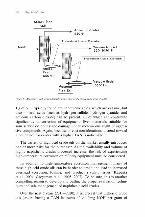
Corrosion at temperatures below 220�C (430�F) has been reportedin several circumstances: (1) in atmospheric overhead systems, lighterorganic acids—such as acetic acid and formic acid—present in theacidic crudes can cause corrosion, (2) in vacuum overhead systems,light organic acids formed by the degradation of naphthenic acids inthe vacuum feed furnace may be present and have also caused corro-sion, and (3) in vacuum systems (Figure 4.1). Corrosion at tempera-tures as low as 180�C has been reported due to true naphthenic acids(Kapusta et al., 2004; Groysman et al., 2005, 2007) although the trueboiling point of these acids would be expected to be much higher.
Besides sulfur, crude contains many species that are quantified bythe TAN of the oil. This number is not specific to a particular acid butrefers to all possible acidic components in the crude and is defined bythe amount of potassium hydroxide required to neutralize the acids in
1 g of oil. Typically found are naphthenic acids, which are organic, butalso mineral acids (such as hydrogen sulfide, hydrogen cyanide, andaqueous carbon dioxide) can be present, all of which can contributesignificantly to corrosion of equipment. Even materials suitable forsour service do not escape damage under such an onslaught of aggres-sive compounds. Again, because of cost considerations, a trend towarda preference for crudes with a higher TAN is noticeable.
The variety of high-acid crude oils on the market usually introducesone or more risks for the purchaser. As the availability and volume ofhighly naphthenic crudes processed increase, the risk of experiencinghigh-temperature corrosion on refinery equipment must be considered.
In addition to high-temperature corrosion management, many ofthese high-acid crude oils can be harder to desalt and lead to increasedoverhead corrosion, fouling, and product stability issues (Kapustaet al., 2004; Groysman et al., 2005, 2007). To be sure, this is anothercompelling reason to develop and outline the proper evaluation techni-ques and safe management of naphthenic acid crudes.
Over the next 5 years (2015�2020), it is forecast that high-acid crudeoils (crudes having a TAN in excess of .1.0 mg KOH per gram of
Predominant Areas of Corrosion
Predominant Areas of Corrosion
Figure 4.1 Atmospheric and vacuum distillation units showing the predominant areas of NAC.
78 High Acid Crudes
crude oil) will continue to increase significantly, with production risingacross the world. All of these crude oils have significant acid numbers.Therefore, corrosion management is of vital importance to ensure that cor-rosion risk to the plant is minimized, a proper inspection system is in placeto identify the corrosion which might occur, and areas of the plant thatmight be subject to severe corrosion are identified so that the need formore corrosion-resistant alloys can be predicted (Johnson et al., 2003).
4.2 PROCESS EFFECTS
In order to gain an economic advantage, many refiners are lookingincreasingly at processing high levels of naphthenic crude oils in theircrude slates (Johnson et al., 2003). Many high-acid crude oils cancause corrosion in high-temperature regions within the refinery, nor-mally around the crude and vacuum towers.
Corrosion by naphthenic acid constituents is manifested in the form ofisolated, deep pits in partially filmed areas and/or impingement attack inessentially film free. Damage is in the form of unexpected high corrosionrates on alloys that would normally be expected to resist sulfidic corro-sion. In many cases, even very highly alloyed materials (i.e., 12 Cr, AISI316 and 317) have been found to exhibit sensitivity to corrosion underthese conditions. NAC is differentiated from sulfidic corrosion by thenature of the corrosion (pitting and impingement) and by its severe attackat high velocities in crude distillation units. Crude feedstock heaters, fur-naces, transfer lines, feed and reflux sections of columns, atmosphericand vacuum columns, heat exchangers, and condensers are among thetypes of equipment subject to this type of corrosion.
There are several important variables to consider while performinga risk assessment on a unit such as: stream analysis, temperature,velocity, metallurgy, and flow regimes (Wu et al., 2004a,b). Everypiece of the puzzle must be analyzed before the best mitigation strate-gies can be developed, including: (1) stream analysis, (2) velocity, (3)two-phase flow, (4) areas of turbulence, (5) predictable zones of firstvaporization or condensation, (6) reactive sulfur content of the variousside-cut oils, (7) metallurgy, (8) other overhead corrosion, desaltingand fouling variables, and (9) side-cut stability.
In the stream analysis, the acid number and naphthenic acid content(from the naphthenic acid titration test (NAT)) (Chapters 1 and 2) for
79Effects in Refining
most crude oils varies with the temperature of distillation fraction. Theresults for the NAT represent only the naphthenic acids within theTAN. There are many different naphthenic acid species, and some aremore corrosive than others. Testing the whole crude and the side cutsshows where the different naphthenic acids will distill and concentrate.It is recommended that such testing is conducted on the anticipatedblends that could be encountered to ensure the contributions of othercrudes to TAN testing and naphthenic acid titration data are obtained.
Typical desalter problems include effluent water with high oil andsolids content (and subsequent problems at the wastewater treatingplant), poor desalting efficiency, uncontrollable emulsions, and basicsediment and water (BS&W) carryover into desalted crude. Effectivewastewater treatment is another key factor in solving the complextreatment challenge.
The same feedstocks that cause desalter problems can also causecrude unit distillation column overhead corrosion problems due to thehigher chloride loadings caused by lower desalter performance.Thermally produced bitumen from the Athabasca oil sands depositsmay also have a high TAN, which can cause upgrader or refineryhigh-temperature NAC problems in the crude unit atmospheric andvacuum distillation systems (Stark et al., 2002; Turini et al., 2011).They can also contribute to crude unit distillation tower overhead cor-rosion problems, as high TANs promote salt hydrolysis to hydrogenchloride and can thermally degrade to form lower molecular-weightorganic acids. These acids can increase both unit neutralizer demandand overhead system corrosion potential.
In addition, to the obvious process such as desalting and distilla-tion, naphthenic acids are implicated in problems with downstreamunits like coking units, hydrotreaters, and fluid catalytic crackingunits (FCCUs). Also, difficulties arise with desalting, and there arerisks of increased fouling due to low API gravities of High acid crudesand their contents of asphaltene constituents, naphthenic acids, andcalcium naphthenates.
The following sections present descriptions of the various processesthat are likely to come into contact with high-acid crudes as well asheavy crude with a tendency to contain high amounts of naphthenicacids (Hau and Mirabal, 1996; Hopkinson and Penuela, 1997).
80 High Acid Crudes
4.3 DESALTING
Desalting crude oil is the first step in refining that has a direct effecton corrosion and fouling. By mixing and washing the crude withwater, salts and solids transfer to the water phase which settles out in atank. An electrostatic field is induced to speed up the separation ofoil and water. In this way, inorganic salts that could cause foulingor hydrolyze and form corrosive acids are largely removed. Often,chemicals are added in the form of demulsifiers to break the oil/wateremulsion. Also, chemicals such as caustic soda are introduced toneutralize acidic components. Uncontrolled feeding of caustic can,however, have a detrimental effect. An excess of caustic can result inthe formation of soap due to, for instance, the presence of fatty acids.Soap stabilizes the oil water mixture and obstructs the separation pro-cess. Also, too strong a mixing of crude and water can create an emul-sion that is very difficult to break. Frequently, the crude arrives at therefinery as an emulsion due to the presence of water that had beenused to maximize the oil extraction from the oil reservoir, or watermight have occurred naturally in the reservoir. It can happen thatemulsions are too strong and prove impossible to break. When this isthe case, a lot of the contaminants end up in downstream processes,which may have serious consequences.
As a first step in the refining process, crude oil often containshydrocarbon gases, hydrogen sulfide, carbon dioxide, formation water,inorganic salts, suspended solids, and water-soluble trace metals whichmust be removed by desalting (dehydration) (Speight and Ozum, 2002;Hsu and Robinson, 2006; Gary et al., 2007; Speight, 2014a).Separators are used to degas produced crude and remove the bulk offormation water. To meet the water content specified by pipeline com-panies, dehydrators are used to remove much of the remaining forma-tion water and a portion of emulsified water.
The typical methods of crude oil desalting (chemical separation andelectrostatic separation) use hot water as the extraction agent. In chem-ical desalting, water and chemical surfactant (demulsifiers) are addedto the crude, heated so that salts and other impurities dissolve into thewater or attach to the water, and then held in a tank where they settleout. Electrical desalting is the application of high-voltage electrostaticcharges to concentrate suspended water globules in the bottom of thesettling tank. Surfactants are added only when the crude has a large
81Effects in Refining
amount of suspended solids. Both methods of desalting are continuous.A third and less-common process involves filtering heated crude usingdiatomaceous earth.
In the process, the feedstock crude oil is heated to between 65�Cand 175�C (150�F and 350�F) to reduce viscosity and surface tensionfor easier mixing and separation of the water—this is particularlyimportant for treating heavy oil. The temperature is limited by thevapor pressure of the crude oil feedstock. In both methods, other che-micals may be added. Ammonia is often used to reduce corrosion.Caustic or acid may be added to adjust the pH of the water wash.Wastewater and contaminants are discharged from the bottom of thesettling tank to the wastewater treatment facility. The desalted crude iscontinuously drawn from the top of the settling tanks and sent to thecrude distillation (fractionating) tower.
Desalting chemicals improve overall desalting efficiency, reducewater and solids carryover with desalted crude, and reduce oil carry-under with brine effluent. Most desalting chemicals are demulsifiersthat help break up the tight emulsion formed by the mix valve andproduce relatively clean phases of desalted crude and brine effluent.Demulsifiers are usually purchased from the same process additivessuppliers that supply antifoulants, filming amine corrosion inhibitors,liquid organic neutralizers and similar products for controlling over-head corrosion, and fouling problems on crude units (or elsewhere inthe refinery). If necessary, demulsifiers can be custom formulated forhigh water removal rates from crudes, but at the cost of poor solidswetting and oil carry-under with the brine discharge. They can also beformulated for high oil removal rates from brine, but at the cost ofwater carryover with desalted crude. When formulated for high solidswetting rates, brine quality often decreases and water carryover withdesalted crude increases.
Chemicals such as caustic soda are also introduced to neutralizeacidic components, which is not always successful in terms ofnaphthenic acid removal. Uncontrolled feeding of caustic can, how-ever, have a detrimental effect. An excess of caustic can result in theformation of soap due to, for instance, the presence of fatty acids.Soap stabilizes the oil water mixture and obstructs the separation pro-cess. Also, too strong a mixing of crude and water can create an emul-sion that is very difficult to break. Frequently, the crude arrives at the
82 High Acid Crudes
refinery as an emulsion due to the presence of water that had beenused to maximize the oil extraction from the oil reservoir, or watermight have occurred naturally in the reservoir. It can happen thatemulsions are too strong and prove impossible to break and thecontaminants end up in downstream processes, which may haveserious consequences.
One process parameter that can play a vital role in both neutraliz-ing acids and demulsification is process pH. Careful monitoring of thepH in the desalter water effluent allows for efficient dosing of causticor acid which may result in significant cost savings. The stability of theoil/water emulsion depends partly on pH. Maintaining the pH of themixture within a certain range helps the demulsifier chemicals inbreaking the emulsion by interacting directly with the water droplets.The speed and quality of the separation process can thus be improvedwhich leads to less water carryover, which in turn can result in asignificant reduction in downstream acid corrosion.
However, naphthenic acid crude constituents in crude oil have natu-ral emulsification tendencies. As the pH of the water inside the desalterincreases, the sodium naphthenates can form very stable emulsions.Maintaining an acidic effluent desalter water is important to combatthe role sodium naphthenates play in desalter upsets.
Processing crude oils containing high levels of calcium naphthenatescan present a number of operating challenges (Piehl, 1988). Two pro-cessing technologies can help refiners successfully process these crudes:(1) use of a metals removal technology developed to remove calcium inthe crude unit desalting operation and (2) chemical treatments in thecrude and vacuum columns.
Several crude oils have come into production within the last fewyears that contain high levels of calcium naphthenates. Typically, thesecrudes are medium to heavy (specific gravity 0.89�0.95, i.e.,17.5�27.5 API), highly biodegraded oils, high in naphthenic acid con-tent, and containing high concentrations of calcium ion in the forma-tion water. Generally, calcium naphthenates found in many crude oilsare insoluble in oil, water, and organic solvents, and this can lead tofouling in separators, hydrocyclones, heat exchangers, and otherupstream production equipment. When blended into refinery crude oilfeedstocks, these crude oils can create a number of processing and
83Effects in Refining
product quality challenges in the tank farm, crude unit, and down-stream units. These processing issues result from several observed attri-butes of crude oil blends containing calcium naphthenates: (1) high-conductivity crude blends, (2) tendency to form stable emulsions, (3)high calcium content of atmospheric and vacuum residua, (4) higherlevels of low-molecular-weight organic acids in crude unit distillationcolumn overheads, and (5) increased high-temperature NAC activity.
In terms of crude oil conductivity (Speight, 2014a), some high-acidcrude oils have a sufficiently high conductivity to interfere with electricdesalters to the point where dehydration is inefficient. In addition tothe corrosion potential from naphthenic acid constituents in the crude,fouling can also occur in downstream units due to corrosionby-products. The corrosion by-product of NAC is iron naphthenate[Fe(naphthenate)2] (Chapter 1). Corrosion mitigation is required toprevent premature fouling/cleanings due to the buildup of NACby-products.
Desalting of high-acid heavy crude oils is much more challenging,and many older desalter systems will need to be enlarged or replacedwith one utilizing a newer desalting technology. Desalter performancecan be hampered by factors, such as the increased salt content in theheavy crudes, as well as the high crude density and viscosity, thatmake oil�water separation more difficult. Moreover, the combinationof asphaltene precipitation and high naphthenic acid concentrationwill increase the tendency to form stable water-in-oil emulsion (raglayer), and potentially cause high oil entrainment in brine water anddifficulty in maintaining the desired BS&W and salt removal at thedesalter outlet.
One of the critical aspects of preventing desalter upsets is the abilityto detect and monitor the emulsion because of the presence of an unde-sirable mixture of dispersed oil, water, and solids (rag layer). The useof conventional level measurement devices, such as guided wave radarand displacer float column, has not been proven as accurate and reli-able in stabilizing the desalter interface levels. The poor rag layerdetection would also often result in relatively high chemical injectionrates to control the rag layer. Instrumentation for level detection(when three phases exist) is available to accurately monitor the raglayer to optimize the desalter performance.
84 High Acid Crudes
4.4 DISTILLATION
The first step in the refining process—after the desalting step—is theseparation of crude oil into various fractions or straight-run cuts bydistillation in atmospheric and vacuum towers. The main fractions or“cuts” obtained have specific boiling point ranges and can be classifiedin order of decreasing volatility into gases, light distillates, middledistillates, gas oils, and residuum.
As the crude oil slate to refineries include heavier crude oils—typically high-acid crude oils—the atmospheric tower and vacuumtower distillate cut points tend to suffer due to increasing difficulty ofvaporization. Therefore, changes can be made such as increasing thetemperature and residue stripping efficiency, lowering the pressure andflash zone oil partial pressure, and modifying the pump-around proto-cols. For the atmospheric unit, other key areas include the oil preheattrain and charge furnace, column internals, and metallurgy of the unitexposed to higher sulfur and naphthenic acids. For the vacuum unit,evaluations should be made of the furnace sizing and outlet tempera-ture, decoking capability, wash-zone capacity, and steam requirement(if it is a wet vacuum column). Deep-cut vacuum distillation via arevamp of the unit to cut deeper into the resid to make additionalfeedstock for the FCCU and/or for hydrocracking unit is always anattractive option to produce higher yield of liquid fuel precursors.
However, such changes can not only lead to NAC but also to anincrease in the rate of corrosion (Mottram and Hathaway, 1971;Blanco and Hopkinson, 1983).
When sulfur is present, iron sulfide scales are formed by sulfur cor-rosion on the inner walls of refinery distilling towers and transfer linesoperating on sour crude oils. Sulfide scales are generally considered topartially reduce corrosion by other corrosive species in crudes,especially naphthenic acids. Sulfur and NAC occur simultaneouslyat similar high temperatures in both atmospheric and vacuum distilla-tion unit.
Iron sulfide scale typically forms a semiprotective barrier againstnaphthenic acid attack. The scale can be removed by high wall shearstress (e.g., high velocity), which exposes the fresh metal beneath tofurther corrosion. Naphthenic acids can also convert iron sulfide to
85Effects in Refining
oil-soluble iron naphthenate, which weakens and helps remove thescale. The presence of more active sulfur species (such as hydrogensulfide) tends to stabilize the sulfide scale against this latter form ofattack. The net result of these effects is that NAC behavior can betime variant, localized, and difficult to predict.
4.4.1 Atmospheric DistillationAt the refinery, the desalted crude feedstock is preheated using recov-ered process heat. The feedstock then flows to a direct-fired crudecharge heater where it is fed into the vertical distillation column justabove the bottom, at pressures slightly above atmospheric and attemperatures ranging from 345�C to 370�C (650�700�F)—heatingcrude oil above these temperatures may cause undesirable thermalcracking. All but the highest boiling fractions flash into vapor. As thehot vapor rises in the tower, its temperature is reduced. Heavy fuel oilor asphalt residue is taken from the bottom. At successively higherpoints on the tower, the various major products including lubricatingoil, heating oil, kerosene, gasoline, and uncondensed gases (whichcondense at lower temperatures) are drawn off.
The fractionating tower, a steel cylinder about 120 ft high, containshorizontal steel trays for separating and collecting the liquids. At eachtray, vapors from below enter perforations and bubble caps (Speight,2014a). They permit the vapors to bubble through the liquid on thetray, causing some condensation at the temperature of that tray. Anoverflow pipe drains the condensed liquids from each tray back to thetray below, where the higher temperature causes reevaporation. Theevaporation, condensing, and scrubbing operation is repeated manytimes until the desired degree of product purity is reached. Then sidestreams from certain trays are taken off to obtain the desired fractions.Products ranging from uncondensed fixed gases at the top to heavy fueloils at the bottom can be taken continuously from a fractionating tower.Steam is often used in towers to lower the vapor pressure and create apartial vacuum. The distillation process separates the major constituentsof crude oil into so-called straight-run products. Sometimes crude oil istopped by distilling off only the lighter fractions, leaving a heavy residuethat is often distilled further under high vacuum.
Many areas of the crude distillation unit can be susceptible to high-temperature NAC. These areas can most simply be identified as those
86 High Acid Crudes
which: (1) are exposed to hydrocarbon fluids that contain corrosivelevels of naphthenic acids, (2) operate at temperatures in the range220�400�C (425�750�F), and (3) are constructed with metallurgy notgenerally considered to be resistant to NAC attack. Stainless steelssuch as 316, 316L, 317, or 317L are generally considered to be resis-tant materials. Additionally, areas of the atmospheric distillation unitthat are susceptible to NAC according to the above parameterstypically include: (1) hot feedstock preheat exchanger network, (2)atmospheric tower heater tubes, (3) atmospheric tower transfer lines,(4) the lower section of the atmospheric tower including lining, traysand associated atmospheric gas oil pump around/product draw system,and atmospheric tower bottoms line and any bottoms heat exchangers,if not integrated with vacuum unit.
4.4.2 Vacuum DistillationIn order to further distill the residuum or topped crude from the atmo-spheric tower at higher temperatures, reduced pressure is required toprevent thermal cracking. The process takes place in one or morevacuum distillation towers. The principles of vacuum distillationresemble those of fractional distillation and, except that larger diame-ter columns are used to maintain comparable vapor velocities at thereduced pressures, the equipment is also similar. The internal designsof some vacuum towers are different from atmospheric towers in thatrandom packing and demister pads are used instead of trays. A typicalfirst-phase vacuum tower may produce gas oils, lubricating oil basestocks, and heavy residual for propane deasphalting. A second-phasetower operating at lower vacuum may distill surplus residuum fromthe atmospheric tower, which is not used for lube-stock processing,and surplus residuum from the first vacuum tower not used fordeasphalting. Vacuum towers are typically used to separate catalyticcracking feedstock from surplus residuum.
4.4.3 Other AreasWithin refineries, there are numerous other, smaller distillation unitsdesigned to separate specific and unique products. Columns all workon the same principles as the towers described above. For example, adepropanizer is a small column designed to separate propane andlighter gases from butane and heavier components. Another larger col-umn is used to separate ethyl benzene and xylene. Small “bubble”
87Effects in Refining
towers called strippers use steam to remove trace amounts of light pro-ducts from heavier product streams.
In furnace tubes and transfer lines, vaporization and fluid velocityare very high. The high-temperature conditions appear to activate evensmall amounts of naphthenic acid in oil increasing corrosion signifi-cantly. Thus, at furnace tubes and transfer lines conditions, the influ-ence of temperature, velocity, and degree of vaporization is very large.Process conditions such as load and steam rate and especially turbu-lence affect corrosivity (Craig, 1995, 1996).
The ancillary areas of the vacuum distillation unit that are suscepti-ble to NAC according to the above parameters typically include: (1)the vacuum heater tubes, (2) the vacuum tower transfer lines, (3) thevacuum tower itself—the lining, trays, packing—and associated lightvacuum gas oil and heavy vacuum gas oil pump around/product drawsystems, (4) the vacuum tower over flash draw and pump-back linesand associated equipment, and (5) the vacuum tower bottoms line andheat exchangers. Other areas of the unit may also be susceptibledepending on crude blend.
4.4.4 Effects of Naphthenic AcidsHigh-temperature corrosivity of distillation units due to the presence ofnaphthenic acids is a major concern to the refining industry. The differ-ence in process conditions, materials of construction, and blend processedin each refinery and especially the frequent variation in the crude slateincreases the problem of correlating corrosion of a unit to a certain typeof crude oil. In addition, a large number of interdependent parametersinfluence the high-temperature crude corrosion process (Chapter 3).
Briefly, processing high-acid crude oils will increase the potentialfor NAC in crude oil distillation units. If not controlled, high-temperature NAC will result in higher equipment replacement costs,lower unit reliability and availability, and increased severity of down-stream unit fouling due to elevated levels of iron naphthenates in crudeunit distillates—which can also affect color stability in distillates fromthe atmospheric distillation unit.
Moreover, despite a good desalting operation, corrosive substancessuch as naphthenic acids (which are not typically removed by a causticwash) can still appear during downstream processing. As an example, the
88 High Acid Crudes
sour (acidic) water corrosion that occurs in the atmospheric tower if pro-duced from the steam, which is injected into the tower to improve thefractionation, condenses in the upper part of the unit. Acidic substanceswill dissolve in the condensate to form an acidic liquid which will causecorrosion in the top section of the tower and in the overhead condenser.This may lead to a requirement of frequent retubing of the condenser andin severe cases to replacement of the entire crude tower top.
For the atmospheric unit, other key areas include the oil preheattrain and charge furnace, column internals, and the metallurgy of theunit exposed to higher sulfur and high TAN. For the vacuum towers,evaluations should be made regarding furnace sizing and outlettemperature, decoking capability, wash-zone capacity, and steamrequirement (if it is a wet column). Deep-cut vacuum distillation via arevamp of the unit to cut deeper into the resid, to make additional feed-stock for a fluid catalytic cracking unit or for a hydrocracking unit feed,is one of the first and most attractive options a refiner should consider.
NAC occurs primarily in high-velocity areas of crude distillationunits in the 220�400�C (430�750�F) temperature range. Lesseramounts of corrosion damage are found at temperatures greater than400�C (750�F), probably due to the decomposition of naphthenic acidsor protection from the coke formed at the metal surface. Velocity and,more important, wall shear stress are the main parameters affectingNAC. Fluid flow velocity lacks predictive capabilities. Data related tofluid flow parameters, such as wall shear stress and the Reynold’sNumber, are more accurate because the density and viscosity of liquidand vapor in the pipe, the degree of vaporization in the pipe, and thepipe diameter are also taken into account. Corrosion rates are directlyproportional to shear stress. Typically, the higher the acid content thegreater the sensitivity to velocity. When combined with high tempera-ture and high velocity, even very low levels of naphthenic acid mayresult in very high corrosion rates.
Most importantly, NAC activity is dependent upon a number ofkey variables, which include but (depending upon the crude oil slateand the refinery equipment) are not limited to: (1) the naphthenic acidcontent of the feedstocks—acid-based corrosion is either reduced oraugmented depending on high or low TAN, (2) sulfur content, (3) sul-fur types, (4) feedstock phase—fluid or vapor, (5) the temperature ofthe metal surfaces being contacted by the corrosive feedstock
89Effects in Refining
constituents, (6) decomposition of the naphthenic acids to lower molec-ular weight acids, (7) condensation of the authentic acids from thevapor phase into a liquid phase, such as condensation and dissolution,and (8) the shear stress of the hydrocarbon moving across the metalsurface, which is a function of velocity and turbulence of the flowingstream.
In terms of the fluid velocity, at low velocity, acid concentrationcaused by boiling and condensing causes corrosive attack, whereas athigh velocity multiphase stream rapid corrosion can occur due to ero-sion�corrosion. Furthermore, NAC is accelerated in furnaces andtransfer lines where the velocity of the liquid/vapor phase is increased.Areas subject to high turbulence of the fluids are also subject to severecorrosion. In addition, turbulence and cavitation in pumps may resultin rapid attack, and the type of alloy in use for high-acid crude oils aswell as surface temperature and shear stresses can also render thesystem susceptible to corrosion by naphthenic acid attack—in somesituations 316 stainless steel, 317 stainless steel, and high-molybdenumalloys (more molybdenum) may offer more resistance to NAC. But itmust be remembered that the effect of the whole system—such as thetypes of crude oil, the chemical structure of the naphthenic acids, andthe equipment—all play a role in determining the occurrence andextent of the corrosion (Chapters 1 and 2) (Speight, 2014b).
NAC is differentiated from sulfidic corrosion by the nature of thecorrosion (pitting and impingement) and by its severe attack at highvelocities in crude distillation units. Crude feedstock heaters, furnaces,transfer lines, feed and reflux sections of columns, atmospheric andvacuum columns, heat exchangers, and condensers are among the typesof equipment subject to this type of corrosion. However, at high tempera-tures, especially in furnaces and transfer lines, the presence of naphthenicacids may increase the severity of sulfidic corrosion. The presence of theseorganic acids may disrupt the sulfide film, thereby promoting sulfidic cor-rosion on alloys that would normally be expected to resist this form ofattack (i.e., 12 Cr and higher alloys). In some cases, such as in side-cutpiping, the sulfide film produced by hydrogen sulfide is believed to offersome degree of protection from NAC. In general, the corrosion rate of allalloys in the distillation units increases with an increase in temperature.
The presence of sulfur compounds with the naphthenic acids consid-erably increases corrosion in the high-temperature parts of the
90 High Acid Crudes
distillation units (Chapters 1 and 2). Isolated deep pits in partially pas-sivated areas and/or impingement attack in essentially passivation-freeareas are typical of NAC. Damage is in the form of unexpected highcorrosion rates on alloys that would normally be expected to resistsulfidic corrosion. In many cases, even very highly alloyed materials(i.e., 12 Cr, AISI types 316 and 317) have been found to exhibitsensitivity to corrosion under these conditions.
The top section of a crude unit can be subjected to a multitude ofcorrosive species. Hydrochloric acid, formed from the hydrolysis ofcalcium and magnesium chlorides, is the principal strong acid responsi-ble for corrosion in the crude unit top section. Carbon dioxide isreleased from crudes typically produced in petroleum recovery opera-tions that involve the use of carbon dioxide flooding fields as well ascrude oils that contain a high content of naphthenic acid.
Mitigation of NAC through process changes includes any action toremove or at least reduce the amount of acid (and acid gases) gaspresent and to prevent the accumulation of water on the tower trays.Material upgrading includes lining of distillation tower tops with alloysresistant to hydrochloric acid. Design changes are used to prevent theaccumulation of water—these include redesign of the coalescers andwater draws. The application of chemicals includes the injection of aneutralizer to increase the pH and a corrosion inhibitor. The presenceof many weak acids, such as fatty acids and carbon dioxide, can bufferthe environment and require greater use of neutralizers. Excessneutralizers may cause plugging of trays and corrosion under the saltdeposits.
A dew point probe is typically placed in a location at least 38�C(100�F) above the calculated dew point temperature. The probe elementsare then cooled internally by cold air injection and the temperature atwhich the first liquid drop forms is determined for the actual conditionsin the tower. The injection point and the amount of chemicals useddepend on the knowledge of the temperature in the tower where conden-sation starts. With the number of corrosive species present, the calculateddew point may be much lower than the actual dew point.
Processing crude oils that have a high content of calcium naphthe-nate derivatives can, as with many high-acid crude oils, result in higherloadings of low-molecular-weight organic acids and carbon dioxide in
91Effects in Refining
the upper portions of the crude and vacuum columns and overheadcondensing systems. The amount and distribution of lower molecularweight acids and carbon dioxide in these systems is a function of thedistribution of organic acid molecular weights in the crude oil, plusheater outlet, side cut, and column overhead temperatures.
In addition to naphthenic acids, the overhead of an atmospheric distil-lation tower crude unit can be subjected to a multitude of corrosive spe-cies: (1) hydrochloric acid, formed from the hydrolysis of calcium andmagnesium chlorides, is the principal strong acid responsible for corro-sion in crude unit overhead, (2) carbon dioxide, released from crudes typi-cally produced in enhanced oil recovery system using carbon dioxide asthe recovery gas flooded fields, (3) hydrogen sulfide, released from sourcrudes, increases significantly corrosion of crude unit overhead, (4) sulfu-ric acid and sulfurous acid, formed by either oxidation of hydrogen sul-fide or direct condensation of sulfur dioxide and sulfur trioxide, and (5)low-molecular fatty acids such as formic acid, HCO2H, acetic acid,CH3CO2H, propionic acid, CH3CH2CO2H, and butanoic acid,CH3CH2CH2CO2H, which are released from crude oils with a high con-tent of naphthenic acid. Any of these acids coming into contact withwater in condensation areas will be increased in the corrosivity potential.Furthermore, the presence in the feedstock of the lower molecular acidscan buffer the environment and require a higher use of neutralizing che-micals. However, excessive amounts of a neutralizer chemical may causeplugging of trays and corrosion under the salt deposits.
Mitigation of this type of corrosion is performed by processchanges, material upgrading, design changes, and injection of chemi-cals such as neutralizers and corrosion inhibitors (Petkova et al., 2009).Process changes include any action to remove or at least reduce theamount of acid gas present and to prevent accumulation of water onthe tower trays. Material upgrading includes lining of distillation towertops with alloys resistant to hydrochloric acid. Design changes areused to prevent the accumulation of water and include coalescers andwater draws. The application of chemicals includes the injection of aneutralizer to increase the pH and a corrosion inhibitor. The presenceof many weak acids such as fatty acids and carbon dioxide can bufferthe environment and require a higher use of neutralizers.
Typically, corrosion inhibitors and neutralizers such as caustic soda orammonia are injected with the aim of increasing the pH of the sour water.
92 High Acid Crudes
Although this is an obvious response to the problem, it is not alwaysadvisable—excess of neutralizer may cause plugging of trays and corro-sion under the salt deposits. For example, the presence of various acidgases and ammonia can result in salt deposition � ammonium bisulfide(NH4HS) is one of the main causes of sour water corrosion. Alkalinity ofthe water (pH .7.6) dramatically increases ammonium bisulfide corro-sion. Overdosing the amount of caustic is easily achieved—as in thedesalting operation, the key to corrosion reduction is in accurate pH con-trol. The application of dew point equipment may offer some benefits formitigating corrosion. The dew point probe is typically placed in a loca-tion at least 38�C (100�F) above the calculated dew point temperature.The probe elements are then cooled internally by cold air injection andthe temperature at which the first liquid drop forms is determined for theactual conditions in the tower. The injection point and the amount of che-micals used depend on the knowledge of the temperature in the towerwhere condensation occurs. With the number of corrosive species present,the calculated dew point may be much lower than the actual dew point.
An additional concern for chemical treatment in the atmospheric dis-tillation unit overhead is the application of the film technology in whichthe corrosion inhibitor forms a thin film on the metallurgy and preventscorrosion. However, if the film-forming inhibitor has surface propertiesthis can cause a water emulsion to occur in the overhead stream (typi-cally a naphtha stream). The water in the stream can cause further cor-rosion problems downstream of the distillation unit—careful selectionof corrosion inhibitors to minimize this effect should be exercised.
Metallurgy will have an impact on the atmospheric and vacuumunits. There are two major causes for concern: sulfidic attack due toincreased sulfur content and (2) NAC, since most heavy crudes resultin sulfidation of the metal as well as naphthenic acid attack. The mostcommon solution to the NAC problem is increased metallurgy in theaffected equipment to 317L stainless steel or alloys with approximately3% w/w molybdenum.
One key parameter that can be very expensive is the transfer tem-perature for products to the downstream units. If the transfer piping iscarbon steel, it is important to maintain the unit transfer temperaturebelow the temperature at which NAC is a concern, typically approxi-mately 205�235�C (400�450�F).
93Effects in Refining
Furthermore, along with the high propensity for cracking, processinghigh-acid heavy sour crudes can lead to a high rate of coke formation,typically concentrated in the vacuum tower heater furnace. To minimizecoke formation, several key mitigation strategies should be incorporatedinto the design such as the use of high fluid velocity in the heater tubes.In addition, a double-fired vacuum heater design will reduce the peakheat flux in the tubes to minimize the coking potential. Also, strippingsteam in the vacuum column shows that this will minimize the requiredvacuum heater outlet temperature for a fixed vacuum resid cut pointand vacuum column diameter.
Several design issues can affect the design and operation of the crudepreheat exchanger train. High-acid heavy crude oils, which typicallyhave a high viscosity that significantly impairs the heat transfer in thecold preheat exchangers, and options to improve heat transfer withvarying baffle configurations or twisted tube bundles are available.
4.5 VISBREAKING
The visbreaking process is a thermal (noncatalytic) process that wasoriginally developed to reduce the resid viscosity to meet the specifica-tions for heavy fuel oil. In the process, the high-boiling feedstock(residuum, heavy oil, tar sand bitumen) is converted to distillable pro-ducts. The thermal reactions are not allowed to proceed to completion,and the hot reaction mix is quenched with a lower boiling (gas oiltype) product (Speight, 2014a). In modern refineries, the process isused to frequently to convert heavy feedstocks into fuel oil into valu-able gasoline and gas oil and produces residual fuel oil sold as marinefuel (Speight and Ozum, 2002; Hsu and Robinson, 2006; Gary et al.,2007; Speight, 2014a). The conversion is low because the process takesplace just before the point of coke formation.
In the process, the feedstock is heated 430�510�C (800�950�F) atatmospheric pressure and mildly cracked in a heater. It is thenquenched with cool gas oil to control excessive cracking and flashed ina distillation tower. The thermally cracked residual material, whichaccumulates in the bottom of the fractionation tower, is vacuumflashed in a stripper and the distillate recycled.
The introduction of opportunity crudes, including high-acid crudes,to refinery slates poses additional challenges for visbreaker optimization.
94 High Acid Crudes
Experience in dealing with frequently changing complex blends hasidentified unappreciated problematic feed characteristics that canseverely limit visbreaker performance due to incompatibility phenom-ena or (more pertinent to the present text) corrosion (Rijkaart et al.,2009; Speight, 2014a).
A major concern with processing high-acid crude oils is blendingand mixtures, since many of the high-acid (heavy) crude oils may beincompatible with other crudes schedule for blending and use by therefinery (Speight, 2014a). Therefore, it is important to use the oil com-patibility test methods to predict the proportions and order of blendingof oils that would prevent incompatibility prior to the purchase andscheduling of crudes (Speight, 2014a).
High-acid crude oils may compete with heavy, sour crudes requiringmore residual processing capacity, such as visbreaking as a pretreatmentprocess prior to sending the visbroken feedstock for further processing.On the other hand, some of the tar sand bitumen blends have high-acidcontent that requires investment in improved metallurgy and chemicaladditives. No matter which resid conversion technology is selected, cokeand sediment formation as well as NAC are often the major concerns.
Organic acids formed by decomposition of naphthenic acids and phenolderivatives (Chapter 2) can cause significant metal loss in visbreaker units(O’Kane et al., 2010a). Corrosion inside the units can part way up the vis-breaker fractionator column on the trays and within the downcomers, andthe corrosion is manifested by the presence of smooth, uniform zones ofmetal loss characteristic of organic acid corrosion. Hydrogen flux measure-ment can be used to track the activity of NAC at 200�C (390�F)—in thevisbreaker fractionator, as in other locations where naphthenic acids occur,the only source of hydrogen in the process stream is likely to be from thecracking of hydrocarbons (Zetlmeisl, 1996; Dean and Powell, 2006;O’Kane et al., 2010a,b; Rudd et al., 2010).
In some visbreakers, smooth, uniform corrosion in highly localizedareas has been found within the downcomer trays, with the amount ofthe corrosion varying depending on the position of the trays. The cor-rosion is typically localized to areas of liquid flow, and the pattern ofthe corrosion suggests a relation to the fluid flow patterns (O’Kaneet al., 2010a,b). It has been reported that the operating temperatures atthe corroded trays were within the lower end of the range at which
95Effects in Refining
NAC has been observed. Additionally, the corrosivity of naphthenicacids was known to be strongly velocity related (Babaian-Kibala et al.,1993; Nugent and Dobis, 1998; Babaian-Kibala and Nugent, 1999).When this occurs, the visual appearance of the corroded areas isgenerally consistent with corrosion by organic acids—specifically, theaffected area may have no adherent scale also there may be brightpatches that appear freshly corroded along with a pattern of surfaceroughness that suggests the corrosion is flow related.
However, any naphthenic acids in the feed to a visbreaker unit wouldneed to be degraded (cracked) to produce lighter acids in order to reachthis upper portion of the column. It is possible for several lower molecu-lar weight organic acids to be formed from naphthenic acids at visbreak-ing temperatures and the boiling points of the individual lowermolecular weight acids may correspond well with the temperature in thearea of highest corrosion, thereby indicating the curative agent forthe corrosion. Other corrosion sites within the unit may also indicatethe severity or lack of severity of the corrosion that is due to acid speciesthat are present in lesser amount than the main corrosive agent.
4.6 COKING
Coking is a severe method of thermal cracking used to convert high-boiling residua as well as heavy oil and tar sand bitumen into lowerboiling products or distillates. Unlike visbreaking in which the thermalreactions are not allowed to proceed to completion, coking is a severemethod of thermal cracking in which cracking to extinction is practised.Coking produces straight-run gasoline (coker naphtha) and variousmiddle-distillate fractions used as catalytic cracking feedstock as well ascoke. The two most common processes are delayed coking and continu-ous (contact or fluid) coking. Three typical types of coke are obtained(sponge coke, honeycomb coke, and needle coke) depending upon thereaction mechanism, time, temperature, and the crude feedstock.
4.6.1 Delayed CokingDelayed coking, a carbon rejection technology, is the most popular wayto upgrade heavy feedstocks. However, in the process, approximately70�80% v/v of the total heavy feedstocks is converted into valuable trans-portation fuels while the remaining portion is downgraded to coke. Thereare three limitations to achieving higher liquid yields: (1) secondary
96 High Acid Crudes
cracking of valuable volatile liquid products, (2) a combination ofsmaller-ring aromatics to form polynuclear aromatics (PNAs), and (3)the formation of PNAs via aromatization of hydroaromatic constituents.To minimize the secondary cracking of volatile liquid products, a cokerreactor with a very short vapor residence time but a lengthy resid resi-dence time is preferred to achieve complete conversion to coke. The latestdevelopments in the conventional delayed coking technology emphasizedesign and operation of major equipment (e.g., coke drums, heaters, andfractionators), coke quality and yield flexibility, and operability andsafety (Radovanovic and Speight, 2011).
In the process, the heated charge (typically residuum from atmo-spheric and vacuum distillation towers) is transferred to large cokedrums which provide the long residence time needed to allow thecracking reactions to proceed to completion. Initially, the heavy feed-stock is fed to a furnace which heats the residuum to high temperatures(900�950�F) at low pressures (25�30 psi) and is designed and con-trolled to prevent premature coking in the heater tubes. The mixture ispassed from the heater to one or more coker drums where the hotmaterial is held approximately 24 h (delayed) at pressures of25�75 psi, until it cracks into lighter products. Vapors from the drumsare returned to a fractionator where gas, naphtha, and gas oils are sep-arated out. The heavier hydrocarbons produced in the fractionator arerecycled through the furnace.
After the coke reaches a predetermined level in one drum, the flowis diverted to another drum to maintain continuous operation. The fulldrum is steamed to strip out uncracked hydrocarbons, cooled by waterinjection, and decoked by mechanical or hydraulic methods. The cokeis mechanically removed by an auger rising from the bottom of thedrum. Hydraulic decoking consists of fracturing the coke bed withhigh-pressure water ejected from a rotating cutter.
The potential exists for exposure to hazardous gases such as hydro-gen sulfide and carbon monoxide, and trace PNAs associated withcoking operations. When coke is moved as a slurry, oxygen depletionmay occur within confined spaces such as storage silos, since wet car-bon will adsorb oxygen. Wastewater may be highly alkaline and con-tain oil, sulfides, ammonia, and/or phenol. The potential exists in thecoking process for exposure to burns when handling hot coke or in theevent of a steam-line leak, or from steam, hot water, hot coke, or hot
97Effects in Refining
slurry that may be expelled when opening cokers. Safe work practicesand/or the use of appropriate personal protective equipment may beneeded for exposures to chemicals and other hazards such as heat andnoise, and during process sampling, inspection, maintenance, and turn-around activities.
When sour and/or high-acid crude oils—including resids where dis-tillation has concentrated naphthenic acids into the resids (Speight andFrancisco, 1990)—are processed in a delayed coking unit, corrosioncan occur where metal temperatures are between 265�C and 485�C(450�F and 900�F). At temperatures in excess of 485�C (900�F), cokeforms a protective layer on the unit/reactor metal. Nevertheless, thefurnace, soaking drums, lower part of the tower, and high-temperatureexchangers are usually subject to corrosion. Hydrogen sulfide corro-sion in coking can also occur when temperatures are not properly con-trolled above 485�C (900�F). NAC in delayed coking units has alsobeen reported in the light cycle gas oils and heavy cycle gas oil streamson delayed coking units processing high-acid feedstocks.
4.6.2 Fluid CokingIn the fluid coking process, cracking occurs by using heat transferredfrom hot, recycled coke particles to feedstock in a radial mixer, calleda reactor, at a pressure of 50 psi. Gases and vapors are taken from thereactor, quenched to stop any further reaction, and fractionated. Thereacted coke enters a surge drum and is lifted to a feeder and classifierwhere the larger coke particles are removed as product. The remainingcoke is dropped into the preheater for recycling with feedstock. Cokingoccurs both in the reactor and in the surge drum. The process is auto-matic in that there is a continuous flow of coke and feedstock.
4.6.3 Effect of Naphthenic AcidsA coking process is one of several options for resid, heavy oil, and tsarsand bitumen processing. The function of the coking unit function is toupgrade the heavy feedstock(s) into more valuable liquid products, andheavy sour crudes have significantly higher amounts of vacuum residin the feed, the coking unit (especially the delayed coker) is typicallyone of the most overwhelmed in terms of capacity.
Although debottlenecking is usually possible by improvements todrum cycle time, most refiners will find that the capacity of their
98 High Acid Crudes
existing coking unit is soon overwhelmed by the amount of heavy feed-stock (containing resid naphthenic acids or heavy oil/tar sand bitumennaphthenic acids) that needs to be processed. Therefore, additionalcoking capacity in the form of a new unit is usually required to signifi-cantly increase the amount of high-acid heavy feedstocks processed bythe refinery.
Most coking units are constructed of alloy that will resist sulfidiccorrosion, but if the feed increases significantly in TAN (naphthenicacid content), some metallurgy reviews are needed. Fortunately, inmany cases, the heater temperatures cause the naphthenic acids todecompose, and it may only occur in the feed area after some preheat-ing that is subject to the risk of corrosion.
4.7 CATALYTIC CRACKING
Catalytic cracking decomposes complex high-molecular-weight feed-stocks into less complex low-molecular-weight products in order toincrease the quality and quantity of lower molecular weight productsand decrease the amount of coke.
Catalytic cracking is similar to thermal cracking except that cata-lysts facilitate the conversion of the heavier molecules into lighter pro-ducts. Use of a catalyst (a material that assists a chemical reaction butdoes not take part in it) in the cracking reaction increases the yield ofimproved quality products under much less severe operating conditionsthan in thermal cracking. Typical temperatures are from 455�C to530�C (850�950�F) at much lower pressures of 10�20 psi. The cata-lysts used in refinery cracking units are typically solid materials (zeo-lite, aluminum hydrosilicate, treated bentonite clay, fuller’s earth,bauxite, and silica�alumina) that come in the form of powders, beads,pellets, or shaped materials (extrudates).
4.7.1 Fluid Catalytic CrackingA typical fluid catalytic cracking process involves mixing a preheatedhydrocarbon charge with hot, regenerated catalyst as it enters the riserleading to the reactor. The charge is combined with a recycle streamwithin the riser, vaporized, and raised to reactor temperature(485�540�C; 900�1000�F) by the hot catalyst. As the mixture travelsup the riser, the charge is cracked at 10�30 psi. In the more modern
99Effects in Refining
FCCUs, all cracking takes place in the riser. The reactor no longerfunctions as a reactor but serves as a holding vessel for the cyclones.This cracking continues until the oil vapors are separated from the cat-alyst in the reactor cyclones. The resultant product stream (crackedproduct) is then charged to a fractionating column where it is sepa-rated into fractions, and some of the heavy oil is recycled to the riser.
Spent catalyst is regenerated to get rid of coke that collects on thecatalyst during the process. Spent catalyst flows through the catalyststripper to the regenerator, where most of the coke deposits burn off atthe bottom where preheated air and spent catalyst are mixed. Freshcatalyst is added and worn-out catalyst removed to optimize the crack-ing process.
NAC takes place where both liquid and vapor phases exist and atareas subject to local cooling such as nozzles and platform supports.Furthermore, when the feedstock is a high-nitrogen feedstock (as isoften the case when heavy oil and tars sand bitumen are included asfeedstock), exposure to ammonia and cyanide may occur, subjectingcarbon steel equipment in the fluid catalytic cracking overhead systemto corrosion, cracking, or hydrogen blistering. These effects may beminimized by water wash or corrosion inhibitors. Water wash mayalso be used to protect overhead condensers in the main column sub-jected to fouling from ammonium hydrosulfide. Inspections shouldinclude checking for leaks due to erosion or other malfunctions such ascatalyst buildup on the expanders, coking in the overhead feeder linesfrom feedstock residues, and other unusual operating conditions.
4.7.2 Effect of Naphthenic AcidsThe catalytic cracking process has also become one of several optionsfor resid, heavy oil, and tsar sand bitumen processing. The function ofthe unit is to upgrade the heavy feedstock(s) into more valuable liquidproducts, and heavy feedstocks crudes have significantly higheramounts of resid in the feed, the catalytic cracking unit is often alsooverwhelmed in terms of capacity. In addition, the amount of heavyfeedstock (containing resid naphthenic acids or heavy oil/tar sand bitu-men naphthenic acids) that needs to be processed continued toincrease. Therefore, additional cracking capacity is required to signifi-cantly increase the amount of high-acid heavy feedstocks processed bythe refinery.
100 High Acid Crudes
Most cracking units are constructed of alloy that will resist sulfidiccorrosion, but if the feed increases significantly in TAN (naphthenic acidcontent), some metallurgy reviews are required. Fortunately, as withother high-temperature units, the heater temperatures cause thenaphthenic acids to decompose, and it may only occur in the feed areaafter some preheating that is subject to the risk of corrosion. While NACis normally not a concern much below 200�C (392�F) (Chapters 1�3), astemperature increases in the feedstock pipes to the unit, the corrosionrates may increase until the temperatures are sufficiently high enough(usually on the order of 420�C, 790�F) to decompose the naphthenicacids to lower molecular weight organic acids. The differential betweenthe TAN and the naphthenic acid titration number (Chapter 1) begins towiden with the naphthenic acid titration number decreasing.
However, as with all units, the major concern with the catalyticcracking units and the ability of the units to accommodate high-acidcrudes is related to the metallurgy. NAC can be a major concern whilethe feedstock is hot. However, many refineries transport the feedstocksoils between units at moderate temperatures (approximately 205�C,400�F) that alleviate the need for upgraded interconnecting pipebetween units. In the catalytic cracking unit, the feedstock is usuallyheated with the catalyst during introduction into the reactor. Once thefeedstock is mixed with the catalyst, this might have an adverse effecton stainless steel alloys (even those without significant molybdenumcontents) from the acidic attack of the naphthenic acid. Therefore, acareful review of the unit configuration and metallurgy is required toensure that either upgraded metallurgy is provided or that catalystmixed with the oil before introduction into the unit does not enhanceNAC. It should be recalled that a corrosion by-product of NAC isiron naphthenate—corrosion mitigation is required to prevent prema-ture fouling due to the buildup of NAC by-products.
4.8 HYDROPROCESSES
Hydroprocesses (hydrogenation processes) are those refining processesin which hydrogen is used in order to control the reaction chemistryand prevent the formation of coke. Hydrogenation processes for theconversion of petroleum fractions and petroleum products may be clas-sified as destructive and nondestructive. Destructive hydrogenation(hydrogenolysis or hydrocracking) is characterized by the conversion
101Effects in Refining
of the higher molecular weight constituents in a feedstock to lowerboiling products. Such treatment requires severe processing conditionsand the use of high hydrogen pressures to minimize polymerizationand condensation reactions that lead to coke formation.
Nondestructive or simple hydrogenation is generally used for thepurpose of improving product quality without appreciable alteration ofthe boiling range. Mild processing conditions are employed so that onlythe more unstable materials are attacked. Nitrogen, sulfur, and oxygencompounds undergo reaction with the hydrogen to remove ammonia,hydrogen sulfide, and water, respectively. Unstable compounds whichmight lead to the formation of gums, or insoluble materials, are con-verted to more stable compounds.
Because of the extent of the cracking versus hydrogenation, hydro-treating processes are the least most severe of the hydrogenation pro-cesses and can be arbitrarily assigned to be the least corrosive.
4.8.1 HydrotreatingCatalytic hydrotreating is a hydrogenation process used to removeabout 90% w/w of contaminants such as nitrogen, sulfur, oxygen, andmetals from liquid petroleum fractions. These contaminants, if notremoved from the petroleum fractions as they travel through the refin-ery processing units, can have detrimental effects on the equipment,the catalysts, and the quality of the finished product. Typically, hydro-treating is done prior to processes such as catalytic reforming so thatthe catalyst is not contaminated by untreated feedstock. Hydrotreatingis also used prior to catalytic cracking to reduce sulfur and improveproduct yields and to upgrade middle-distillate petroleum fractionsinto finished kerosene, diesel fuel, and heating fuel oils. In addition,hydrotreating converts olefins and aromatics to saturated compounds.
In the hydrotreating for sulfur removal process (hydrodesulfuriza-tion), the feedstock is deaerated and mixed with hydrogen, preheatedin a fired heater (315�425�C; 600�800�F), and then charged underpressure (up to 1000 psi) through a fixed-bed catalytic reactor. In thereactor, the sulfur and nitrogen compounds in the feedstock are con-verted into hydrogen sulfide and ammonia. The reaction productsleave the reactor and after cooling to a low temperature enter a liquid/gas separator.
102 High Acid Crudes
The hydrogen-rich gas from the high-pressure separation is recycledto combine with the feedstock, and the low-pressure gas stream rich inhydrogen sulfide is sent to a gas-treating unit where hydrogen sulfide isremoved. The clean gas is then suitable as fuel for the refinery fur-naces. The liquid stream is the product from hydrotreating and is nor-mally sent to a stripping column for removal of hydrogen sulfide andother undesirable components. In cases where steam is used for strip-ping, the product is sent to a vacuum drier for removal of water.Hydrodesulfurized products are blended or used as catalytic reformingfeedstock.
4.8.2 HydrocrackingHydrocracking is a two-stage process combining catalytic crackingand hydrogenation, wherein heavier feedstocks are cracked in the pres-ence of hydrogen to produce more desirable products. The processemploys high pressure, high temperature, a catalyst, and hydrogen.Hydrocracking is used for feedstocks that are difficult to process byeither catalytic cracking or reforming, since these feedstocks are char-acterized usually by a high content of polycyclic aromatic constituentsand/or high concentrations of the two principal catalyst poisons, sulfurand nitrogen compounds.
The hydrocracking process largely depends on the nature of thefeedstock and the relative rates of the two competing reactions, hydro-genation and cracking. Heavy aromatic feedstock is converted intolighter products under a wide range of very high pressure(1000�2000 psi) and high temperature (400�475�C; 750�1000�F), inthe presence of hydrogen and special catalysts. The process is used forfeedstocks that are difficult to process by catalytic cracking � thesefeedstocks are characterized by a high content of polycyclic aromaticconstituents and/or high concentrations of sulfur and nitrogen com-pounds, which poison the catalyst.
In the first stage, preheated feedstock is mixed with recycled hydro-gen and sent to the first-stage reactor, where catalysts convert sulfurand nitrogen compounds to hydrogen sulfide and ammonia. Limitedhydrocracking also occurs. After the product leaves the first stage, it iscooled and liquefied and run through a hydrocarbon separator. Thehydrogen is recycled to the feedstock and the liquid is charged to afractionator. Depending on the products desired (gasoline components,
103Effects in Refining
jet fuel, and gas oil), the fractionator is run to cut out some portion ofthe first-stage reactor outturn. Kerosene-range material can be takenas a separate side-draw product or included in the fractionator bottomswith the gas oil.
The fractionator bottoms are again mixed with a hydrogen streamand charged to the second stage. Since this material has already beensubjected to some hydrogenation, cracking, and reforming in the firststage, the operations of the second stage are more severe (higher tem-peratures and pressures). Like the outturn of the first stage, thesecond-stage product is separated from the hydrogen and charged tothe fractionator.
Because of the operating temperatures and presence of hydrogen,the hydrogen sulfide content of the feedstock must be strictly con-trolled to a minimum to reduce the possibility of severe corrosion.Corrosion by wet carbon dioxide in areas of condensation also mustbe considered. When processing high-nitrogen feedstock, the ammoniaand hydrogen sulfide form ammonium hydrosulfide, which causes seri-ous corrosion at temperatures below the water dew point. Ammoniumhydrosulfide is also present in sour water stripping.
4.8.3 Effect of Naphthenic AcidsHydrotreaters are one of the most impacted areas of the refinery as theamount of heavy sour crude increases. Typically, there is significantlymore sulfur and aromatics in the products from the atmospheric andvacuum distillation units that need hydroprocessing. Additionally, thecoking units will also be producing more distillate and gas oil that alsomust be hydroprocessed.
With the incremental changes in the feed quality to the unit, such asthe blending of high-acid crude oils into the unit feedstock, the demandfor hydrogen to achieve the product specifications increases. But, themajor concern with the hydroprocessing units and the ability to handlehigh-acid crudes will be related to the metallurgy. As with the atmo-spheric and vacuum distillation sections, the NAC can be a major con-cern while the material is hot. However, many refineries transport thefeedstocks between units at moderate temperatures (approximately205�C, 400�F) that alleviate the need for upgraded interconnectingpipe between units.
104 High Acid Crudes
However, in the hydroprocessing unit, the feedstock is usuallyheated as part of the process. Furthermore, once the feedstock is mixedwith hydrogen, this prevents 300 series SS alloys (even those withoutsignificant molybdenum contents) from experiencing the acidic attackof the naphthenic acid. Therefore, a careful review of the unit configu-ration is required to ensure that either upgraded metallurgy is providedor that hydrogen is mixed with the oil before heating.
4.9 MITIGATION OF NAC
In order to design and plan a mitigation strategy for any refinery pro-cess or unit, it is necessary to know (in this contact, review) theaffected units and equipment. Consideration must also be given to pip-ing systems, which are particularly susceptible in areas of high velocity,turbulence, or change of flow direction, such as pump internals, valves,elbows, tees, and reducers as well as areas of flow disturbance such asweld beads and thermowells. The reactor internals may also be cor-roded in the flash zones, where high-acid streams condense or high-velocity droplets impinge. Furthermore, NAC may also (some mightsay, is likely to) be found in heated feedstock streams downstream ofthe atmospheric tower and vacuum tower but upstream of any hydro-processing reactor.
The NAC in any unit or reactor is characterized by localized corro-sion, pitting corrosion, or flow-induced grooving in high-velocity areas(Chapters 2 and 3). In low-velocity condensing conditions, many alloysincluding carbon steel, low-alloy steels, and 400 series stainless steelsmay show uniform corrosion in terms of loss in thickness and/orpitting (Chapters 2 and 3).
Once the corrosion had been identified and characterized, there areseveral strategies (related to naphthenic acid constituents � other typesof corrosion may require different strategies. The strategies can beimplemented after identification of susceptible areas of the unit as wellas monitoring the corrosion.
The first part of a strategy to mitigate naphthenic acid corrosion is tocarry out a comprehensive analytical assessment of the crude oil whichmust include a detailed assessment of the naphthenic acid content, thetypes of naphthenic acids, and the potential for corrosivity (Chapters 1and 2). This should also include a detailed assessment of the process
105Effects in Refining
operating conditions and the character and structure of the processingunit(s). Furthermore, an important part of the strategy is the design andimplementation of a comprehensive corrosion-monitoring program. Aneffective corrosion-monitoring program will help confirm which areas ofthe unit require a corrosion mitigation strategy, which will provide infor-mation about the impact of any necessary corrosion mitigation steps.
The correctly applied strategy should provide (1) a complete under-standing of the unit operating conditions, (2) crude oil properties, (3)distillate properties, (4) unit/reactor metallurgy, and (5) equipment per-formance history thereby allowing a probability of failure analysis tobe performed for those areas which would be susceptible to NAC.From the results, each unit/reactor in the processing circuit can beassigned a relative probability failure rating based on the survey dataand overall refining industry experience.
Investigations into the appearance of corrosion in the vacuum towermay be due to the occurrence of naphthenic acids or their degradationproducts in the vacuum tower feedstock. In the vacuum column, pref-erential vaporization and condensation of naphthenic acids increasethe TANs of condensates.
The corrosion is similar to corrosion caused by very high TAN frac-tions in which it is believed that, in such a case, and velocity may havevirtually no effect on the process. The naphthenic acids are most activeat their boiling point, but the most severe corrosion generally occurs oncondensation. The corrosion mechanism is mainly a condensate corro-sion and is directly related to content, molecular weight, and boilingpoint of the naphthenic acid. Corrosion is typically more severe at thecondensing point corresponding to high TAN and temperature.However, in general, vacuum-tower overhead corrosion fromnaphthenic acid species is normally less severe than atmospheric-toweroverhead corrosion because of the large volume of steam that condensesalong with the hydrogen in vacuum towers. This steam originates aseither bottom-stripping steam or motive steam to the first-stage jet.
In the vacuum tower, preferential vaporization and condensation ofnaphthenic acids increase the TANs of condensates. There is very littleeffect of fluid velocity. Corrosion takes place only in the liquid phase.It is mainly a condensate corrosion and is directly related tocontent, molecular weight, and boiling point of the naphthenic acid.
106 High Acid Crudes
Corrosion is typically severe at the condensing point corresponding tohigh TAN and temperature. Simulating vacuum tower corrosionrequires the specimens to be exposed in the condensing phase and notin the vapor or liquid phase. This requires apparatus common to cor-rosion studies in the chemical industry. An autoclave and a flow loopjet impingement are not adequate for testing corrosion in this case.
Also in the vacuum tower, as is the case in the atmospheric tower,preferential vaporization and condensation of naphthenic acids increasethe TAN of the condensates. The naphthenic acids are most active attheir boiling point, but the most severe corrosion generally occurs wherethere is condensation of the naphthenic acids (i.e., in the liquid phase).The corrosion mechanism is mainly a condensate corrosion phenome-non and is directly related to naphthenic acid content, molecular weight,and boiling point of the naphthenic acid. Furthermore, corrosion is typ-ically severe at the condensing point corresponding to high TAN andtemperature.
For distillation units and/or components of distillation systems(including the fractionators associated with coking, cracking, andhydroprocessing units) that have not been designed for resistance tocorrosion by naphthenic acids, the options are to: (1) change orblend crude oils, (2) upgrade the metallurgy of the system, (3) utilizechemical inhibitors, (4) remove the naphthenic acids prior to entryinto the refinery proper, that is, after desalting but before distillationor any other form of processing, or (5) some combination thereof(Chapter 5).
Whatever the method chosen, a program of inspection and monitor-ing must be followed. This should include monitoring the TAN (anyother necessary test method) and sulfur content of the crude oil feed-stock and side streams to determine the distribution of acids in the distil-lation fractions from the atmospheric tower and the vacuum tower. Thiscan be (should be) accompanied by ultrasonic testing and radiographictesting for reactor/pipe thickness monitoring. In some cases, localizederosion may be difficult to locate so radiographic testing should be theprimary detection method followed by ultrasonic thickness measure-ment. Electrical resistance corrosion probes and corrosion coupon rackscan be used, and streams can be monitored for iron and nickel contentto assess corrosion in the system (Speight, 2014b).
107Effects in Refining
Finally, sulfidation is a competing and complimentary mechanismwhich must be considered in most situations with corrosion due to thepresence of naphthenic acids. In cases where thinning is occurring, it isdifficult to distinguish between NAC and sulfidation.
The corrosion mechanism at the furnace tubes, transfer lines, areasof high turbulence such as thermowells and pumps is most likely anaccelerated corrosion due to the velocity and the two-phase flow.Simulation of these conditions in the laboratory requires conditions ofhigh degree of vaporization and relatively low wall shear stress, espe-cially conditions that bear a strong relationship to the reality of refin-ery units and refinery operations.
In side-cut piping, conditions of low vaporization and medium fluidvelocity exist. Some studies showed a possible inhibition of NAC bysulfur compounds. In these conditions, an increase in velocity increasescorrosion rates up to the point where impingement starts and corrosionis accelerated dramatically. The corrosion process is dependent onflow, temperature, materials of construction, as well as naphthenicacid content and hydrogen sulfide content.
Process conditions such as load and steam rate and especially turbu-lence affect corrosivity. The presence of any naphthenic acid most likelyincreases sulfidic corrosion. The mechanism of corrosion mechanism atthe furnace tubes, transfer lines, areas of high turbulence such as ther-mowells and pumps is most likely due to an accelerated corrosion reac-tion caused by the high fluid velocity as well as two-phase flow.
In addition to the atmospheric tower and vacuum tower sections,other sections of the refinery susceptible to corrosion include (but maynot be limited to) preheat exchanger (caused by hydrogen chloride andhydrogen sulfide), preheat furnace and bottoms exchanger (caused byhydrogen sulfide and sulfur compounds), atmospheric tower and vac-uum furnace (caused by hydrogen sulfide, sulfur compounds, andorganic acids). Where sour crudes are processed, severe corrosion canoccur in furnace tubing and in both atmospheric and vacuum towerswhere metal temperatures exceed 235�C (450�F). Wet hydrogen sulfidealso will cause cracks in steel. When processing high-nitrogen crudes,nitrogen oxides can form in the flue gases of furnaces. Nitrogen oxides(NOx) are corrosive to steel when cooled to low temperatures in thepresence of water.
108 High Acid Crudes
Chemicals are used to control corrosion by hydrochloric acid pro-duced in distillation units. Ammonia may be injected into the overheadstream prior to initial condensation, and/or an alkaline solution maybe carefully injected into the hot crude-oil feed. If sufficient wash wateris not injected, deposits of ammonium chloride can form and causeserious corrosion. Crude feedstock may contain appreciable amountsof water in suspension which can separate during startup and, alongwith water remaining in the tower from steam purging, settle in thebottom of the tower. This water can be heated to the boiling point andcreate an instantaneous vaporization explosion upon contact with theoil in the unit.