Support all forms of mobilitySupport mobility for all types of applicationsSupport mobility across heterogeneous radio systemsSupport session (service) continuityGlobal roaming
A network performs paging by sending one or multiple paging messages to a paging area where the mobile is likely to be located. Paging areas do not have to be identical to
location areas.Upon receiving a paging message, a mobile needs to update its precise current location with the network. The mobile may also need to establish the
Handoffs in an IP-based wireless network may occur at different protocol layers.Handoffs at each protocol layer may occur in different scopes.Handoffs can be hard or soft.
Mobility at different protocol layers can be managed by different protocols.Mobility management at the IP layer may be independent of mobility management at the lower protocol layers.
Network access control for visiting mobilesRoaming Agreement between the mobile’s home domain and the visited domainsSession continuity while a user crosses domain boundaries
4.2.1 Naming and Addressing of IP Terminals 4.2.2 Mobile IPv4 4.2.3 MIPv4 Regional Registration 4.2.4 Paging Extensions to Mobile IPv4 4.2.5 Mobile IPv6 4.2.6 SIP-based Mobility Management 4.2.7 Cellular IP 4.2.8 HAWAII
4.2.2.1 Agent Discovery4.2.2.2 Movement Detection4.2.2.3 Leaving the Home Network4.2.2.4 Entering and Staying in a Visited Network4.2.2.5 Returning to the Home Network4.2.2.6 Mobile-Home Authentication Extension4.2.2.7 Vendor/Organization Specific Extensions to
Mobile IP Messages4.2.2.8 Reverse Tunneling4.2.2.9 Limitations of MIPv44.2.2.10 MIPv4 Route Optimization
Home address: a globally unique and routable IP address preconfigured or dynamically assigned
Home network: the network whose network address prefix matches that of the mobile terminal’s home addressHome agent (HA) maintain up-to-date location information for the mobile intercept packets addressed to the mobile’s home address tunnel packets to the mobile’s current location
4.2.2.1 Agent DiscoveryThe process for a mobile terminal to discover the mobility agents and receive information from these agentsAchieved by the mobility agents advertising their services and system information to the mobiles via Agent Advertisement messagesA mobile may solicit an Agent Advertisement message from any mobility agent by sending an Agent Solicitation message Mobile-Agents Multicast Group address 224.0.0.11
Uses the Internet Control Message Protocol (ICMP) Router Discovery Message ICMP Router Advertisement Message ICMP Router Solicitation Message
In addition to registering a CoA, a mobile terminal can also use Registration Request messages to Discover the address of a home agent Discover the mobile’s home address, if the mobile
is not configured with a home address Renew a registration that is due to expire Deregister with the HA when the mobile returns
TypeS: Simultaneous bindingsB: Broadcast datagramsD: Decapsulation by mobile terminalM: Minimal encapsulationG: GRE encapsulationr: This field will always be zero and ignored on receptionT: Reverse Tunneling requestedx: This field will always be zero and ignored on receptionLifetime A zero lifetime indicates a request for deregistration.
Home Address Preconfigured 0.0.0.0: no home address or dynamically assign a home
address Can use NAI to identify the mobile by using the Mobile Node
NAI Extension HA will assign a home address in the Registration Reply
messageHome Agent IP address of HA Dynamic Home Agent Address Resolution: the mobile does
not know the address of its HA Mobile sends the Registration Request to the subnet-directed
broadcast address of its home network HA will reject the registration and returns a Registration Reply The mobile therefore can learn the IP address of the HA by
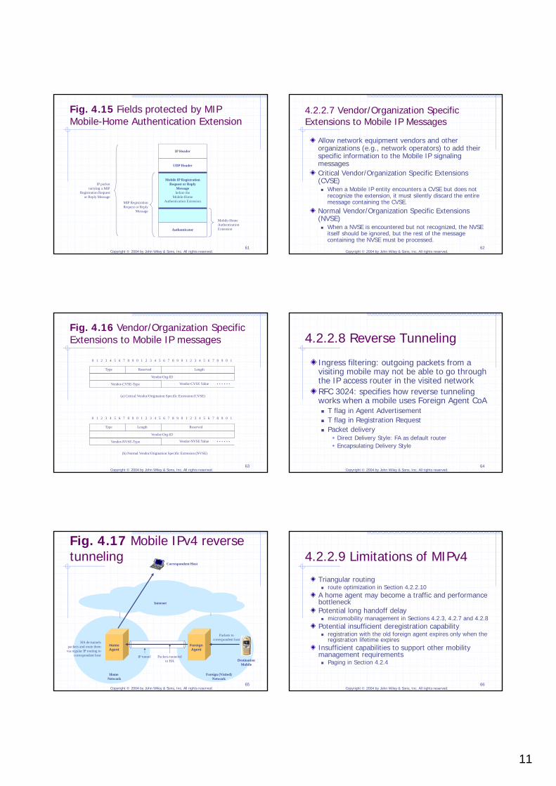
4.2.2.7 Vendor/Organization Specific Extensions to Mobile IP Messages
Allow network equipment vendors and other organizations (e.g., network operators) to add their specific information to the Mobile IP signaling messagesCritical Vendor/Organization Specific Extensions (CVSE) When a Mobile IP entity encounters a CVSE but does not
recognize the extension, it must silently discard the entire message containing the CVSE.
Normal Vendor/Organization Specific Extensions (NVSE) When a NVSE is encountered but not recognized, the NVSE
itself should be ignored, but the rest of the message containing the NVSE must be processed.
Ingress filtering: outgoing packets from a visiting mobile may not be able to go through the IP access router in the visited networkRFC 3024: specifies how reverse tunneling works when a mobile uses Foreign Agent CoA T flag in Agent Advertisement T flag in Registration Request Packet delivery
Direct Delivery Style: FA as default router Encapsulating Delivery Style
Allow a correspondent node (CN) to be aware of a mobile’s current CoA and then tunnel packets to the destination mobile’s CoA directlyBinding Cache: maintained by a CN to map the mobiles’ home addresses to their CoAsBinding Update: HA informs CN the mobile’s current CoAA security association between the CN and the HA needs to be established scalability
Long handoff delay in basic MIPv4: a mobile has to register with its HA every time it changes its CoAMIPv4 Regional Registration: allow a mobile to register its new CoA locally with its visited network domain Each network domain consists of two or more
hierarchical levels of foreign agents Gateway Foreign Agent (GFA)
Paging in Mobile IP (P-MIP) Active Timer: determine a mobile is in active or idle state
active state: standard MIP idle state: may not perform MIP registration no explicit signaling messages
Registered FA the FA through which a mobile performed its last MIP
registration responsible for keeping track of whether the mobile is in active
or idle state by using Active Timer an FA is required on each IP subnet
Paging Area: an idle mobile does not have to perform MIP registration when moving inside the same paging area Paging Area Identifier (PAI): carried by Agent Advertisement A mobile compares the PAIs received from different FAs to
determine whether it has moved into a new Paging Area.
The value of the Active Timer depends on the nature of the traffic. The value of the Active Timer should be longer than the
inter-packet arrival times. Adjusting the Active Timer value dynamically will require the
mobile to send signaling messages to inform its Registered FA of the new Active Timer value.
The value of the Active Timer maintained on the mobile should be the same as (or at least not significantly different from) the value of the Active Timer used by the mobile’s Registered FA for the mobile. An FA needs to know the value of the Active Timer for each
Similar concepts as in MIPv4, but no FA Mobiles use only co-located care-of addresses. Standard IPv6 Neighbor Discovery can be used to
help mobiles to detect movement. (Section 4.2.5.1)Binding: association between a mobile’s home address and its care-of address Binding Update (BU, Section 4.2.5.4) Binding Acknowledgment (BA, Section 4.2.5.4) Authentication of BU and BA messages is achieved
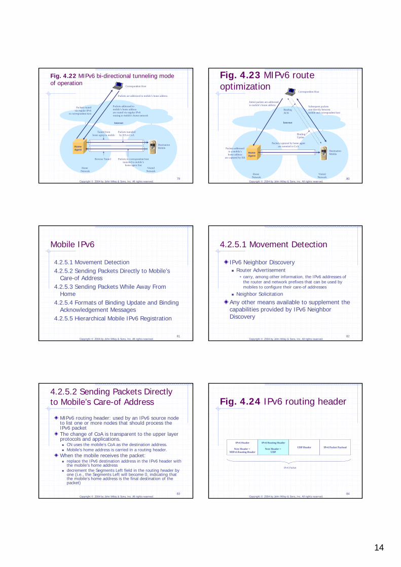
4.2.5.2 Sending Packets Directly to Mobile’s Care-of Address
MIPv6 routing header: used by an IPv6 source node to list one or more nodes that should process the IPv6 packetThe change of CoA is transparent to the upper layer protocols and applications. CN uses the mobile’s CoA as the destination address. Mobile’s home address is carried in a routing header.
When the mobile receives the packet: replace the IPv6 destination address in the IPv6 header with
the mobile’s home address decrement the Segments Left field in the routing header by
one (i.e., the Segments Left will become 0, indicating that the mobile’s home address is the final destination of the packet)
Mobile node may use its current CoA as the source IPv6 address in order to pass the access routers without having to use reverse tunneling use IPv6 Destination Options Header
a Home Address Option will be carried inside an IPv6 Destination Option header
A CH (or HA) will drop the packet if it does not have a binding entry in its
binding cache for the home address carried in the Home Address Option; otherwise
replace the source IPv6 address with the home address carried in the Home Address Option
Binding UpdateSequence NumberA (Acknowledge): request a BA message be returned upon receipt of the BU messageH (Home Registration): request that the receiving node act as the sending node’s HAL (Link-Local Address Compatibility): set when the home address has the same interface identifier as the link-local addressK (Key Management Mobility Capability): indicate whether the protocol used for establishing the IPsec security association can survive movement only valid in a BU message sent to a HA
ReservedLifetime: the number of time units remaining before the binding expiresMobility Options: a variable-length field that contains one or more Mobility Options in a Type-Length-Value format
Statue: indicate the status of how the corresponding BU message is processedK: indicate whether the protocol used by HA for establishing the IPsec security association can survive movementReservedSequence Number: copied from the corresponding BULifetimeMobility Options Binding Authorization Data option Binding Refresh Advice option: used by a home agent to
inform a mobile how often the mobile should send a new BU message to the home agent.
Main reasons for SIP-based mobility management SIP is currently the protocol of choice for signaling and
control of real-time voice and multimedia applications over IP networks.
Significant efforts in the research community and the industry have been devoted to supporting mobility using SIP.
SIP appears to be the only application-layer protocol that can be readily extended to support terminal mobility today.
SIP already supports user mobility.Key difference between SIP-based mobility management and Mobile IP: SIP servers may only participate in setting up the application sessions between the end users Solve the triangular routing problem SIP servers will not likely become bottlenecks
Detection of an IP network change and acquiring new IP addresses may be achieved using any available means to the mobile and do not have to be part of the SIP protocol.Should inform the SIP application of the address change
A SIP Redirect Server in a mobile’s home network tracks the mobile’s current location and provides the location information to a caller so that the caller can contact the mobile at its new location directly to setup a SIP session.The SIP Redirect Server in a user’s home network learns about the user’s current location from the SIP REGISTRATION messages received from the user.
Mobile sends a new SIP INVITE message to invite the correspondent host to re-establish the SIP session to the mobile’s new location.Mobile also updates its location with its home SIP Redirect Server.
A mobile will have to register its new IP address with a SIP server in the mobile’s home network every time the mobile changes its IP address. long handoff delays when the mobile is far away from its
home network may be solved by hierarchical registration
It is difficult for SIP-based mobility management to keep a TCP session alive while a mobile changes its IP address. a mobile terminal and a correspondent host may use a
SIPEYE agent to hide the IP address change from the on-going TCP sessions
Designed to support fast handoff in a wireless network of limited size, for example, a network within the same administrative domainReduce handoff latency by eliminating the need for a mobile to change its IP address while moving inside a Cellular IP networkUse host-specific routing routing and packet forwarding based on the full IP address maintain a host-specific downlink route for forwarding
packets to each individual mobile, rather than maintaining a route for each IP address prefix as with regular IP routing protocols
Similar to Cellular IP, HAWAII (Handoff-Aware Wireless Access Internet Infrastructure) is designed to support fast handoff and paging inside a wireless network under a single administrative domain. reduce handoff latency use host-specific routing
HAWAII and Cellular IP differ in routing and mobility management implementations.
4.3.1 Packet Mobility Management (PMM) Context and States
4.3.2 Location Management for Packet-Switched Services
4.3.3 Routing Area Update 4.3.4 Serving RNS Relocation 4.3.5 Hard Handoffs 4.3.6 Paging Initiated by Packet-Switched Core Network 4.3.7 Service Request Procedure 4.3.8 Handoff and Roaming Between 3GPP and Wireless
As discussed in Chapter 2, all packet-switched user data to and from a mobile is first sent to the mobile’s serving GGSN.The mobile and its serving GGSN use a host-specific route to exchange user data.Therefore, mobility management in 3GPP PS domain is, in essence, to manage the changes of the host-specific route between each mobile and its serving GGSN. A mobile does not have to maintain all the traffic bearers in
the RAN or the CN if it does not expect to send or receive user data soon.
The mobile does not even need to maintain its dedicated signaling connection to the SGSN at all times.
There is no communication between the mobile and the SGSN.The mobile and the SGSN do not have valid location or routing information for the mobile. The mobile does not react to system information related to the SGSN. The SGSN cannot reach the mobile.
The SGSN and the mobile have established a PMM context for the mobile.A dedicated signaling connection is established between the mobile and the SGSN.A mobile’s location inside the RAN is tracked by the RNCs at an accuracy level of radio cells.
The SGSN and the mobile have established the PMM contexts for the mobile. No signaling or traffic connection exists between the mobile and the SGSN.The mobile’s location is tracked by the SGSN at an accuracy level of a Routing Area (Section 4.3.2). The mobile is reachable by the CN via paging.
When the mobile’s PMM state transitions from PMM-CONNECTED to PMM-IDLE subsequently, the mobile’s existing active PDP contexts will continue to remain in ACTIVE state on the GGSN and the SGSN. Reduce the time for a mobile to change from
PMM-IDLE state back to PMM-CONNECTED state Make it easier for the PS CN domain to support
paging Allow the GGSN to always know a mobile’s serving SGSN GGSNs do not have to be aware of the paging operations
RRC-CONNECTED mode: A mobile in RRC-CONNECTED mode has an established RRC connection.RRC-IDLE mode: A mobile in RRC-IDLE mode has not established any RRC connection.
The same RRC connection is used by the mobile to transport all signaling traffic and user traffic for its CS and PS services.
The mobile enters a new Routing Area.The mobile’s periodic routing area update timer expires.The mobile is directed by the network to re-establish its RRC connection.The mobile’s Network Capability changes. A mobile’s Network Capability is a set of
information describing the mobile’s non radio-related capability. For example, information needed for performing ciphering and authentication.
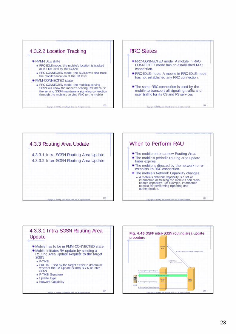
Mobile has to be in PMM-CONNECTED stateMobile initiates RA update by sending a Routing Area Update Request to the target SGSN P-TMSI Old RAI: used by the target SGSN to determine
Upon negative validation of the P-TMSI The source SGSN will send an appropriate error cause to the
target SGSN, which will trigger the target SGSN to initiate the security procedures directly with the mobile to authenticate the mobile.
If this authentication is positive, the target SGSN will send another SGSN Context Request message to the source SGSN to retrieve the mobile’s PMM context and PDP context.
After RAU, the host-specific route is also updated.
Relocate Iu connections from the old serving RNC to the new serving RNCThis section assumes that before the relocation, the mobile’s serving RNC is using the Iur interface to forward signaling and user traffic to another RNC, which in turn delivers the user traffic to the mobile.
Only the source RNC can initiate Serving RNS Relocation. Based on measurement results of the quality of
the radio channels to the mobile and based on its knowledge of the RAN topology
Send a RANAP Relocation Required message to the source SGSN Relocation Type: “UE not Involved” or “UE Involved” Source ID: Identifier of the source RNC Target ID: Identifier of the target RNC Source RNC to target RNC transparent container:
information needed by the target RNC to perform serving RNC relocation including security information, RRC context
Inter-RNC hard handoff without Iur interface Only the source RNC can initiate the inter-RNC hard handoff process. RANAP Relocation Required message to the source
SGSN Relocation Type: UE Involved
Relocation Request Acknowledge: carry an extra information element - Target RNC to Source RNC Transparent Container contain all the radio-related information that the
mobile will need in order to tune its radio to the radio channels of the target RNS
4.3.6 Paging Initiated by Packet-Switched Core Network
A mobile in PMM-IDLE stateThe SGSN initiates paging by sending a RANAP Paging message to every RNC in the Routing Area Identities of the mobile to be paged CN Domain Identifier Area
4.3.8 Handoff and Roaming Between 3GPP and Wireless LANs
Handoff between 3GPP and IP networks using Mobile IPSample signaling flow for handoff between 3GPP and IP networks using MIPv4Mobile terminals with dual home addresses
As discussed in Chapter 2, all user IP packets to and from a mobile are sent first to the mobile’s serving PDSN, which in turn forwards the packets towards their final destinations. A mobile and its serving PDSN maintains a PPP connection and use it as the link layer for exchanging user IP packets. Radio Bearer between the mobile and a BSC A8 connection between BSC and a PCF A10 connection (i.e., R-P connection) between the PCF and
the mobile’s serving PDSN An optional P-P (PDSN-to-PDSN) connection between the
mobile’s serving PDSN and a target PDSN to support fast inter-PDSN handoff
Intra-PDSN HandoffThe mobile’s PPP connection to its serving PDSN does not need to change. The mobile does not need to change its IP address. The mobile does not have to perform registration
with its home agent if Mobile IP is used.Some or all of the bearers that make up the path of the PPP connection may need to be changed. Inter-BTS handoff: change Radio Bearers Inter-BSC handoff: change Radio Bearers, A8/A9
connections Inter-PCF handoff: change Radio Bearers, A8/A9 and
A bidirectional traffic radio channel is established between the mobile and the BSC.The A8/A9 and A10/A11 connections are established for the mobile.The mobile and its serving PDSN maintains a PPP connection.When Mobile IP is used for mobility management, the mobile will have already performed Mobile IP registration with its home agent.
No traffic radio channel exists between the mobile and the BSC. No A8 connection exists for the mobile.The mobile’s A10 connection is maintained. The PPP connection between the mobile and its serving PDSN will be maintained.
There is no traffic radio channel between the mobile and the BSC. No A8/A9 or A10/A11 connection exists for the mobile. No PPP connection exists between the mobile and the PDSN.
State MaintenanceThe Packet Data Service States are maintained in both PCF and mobile terminal.The PDSN will not be aware whether a mobile is in Active or DORMANT state.
4.4.2 Location Management for Packet Data Services
Packet Zone: geographical area served by a single PCF uniquely identified by a Packet Zone ID (PZID)
Each BS periodically broadcasts, over the broadcast radio channels, the PZID of the Packet Zone it serves. A dormant mobile will be able to receive such broadcast system information and use it to determine whether it has moved into a new Packet Zone. 3GPP2 does not define any new protocol, message, or
procedure uniquely for performing Packet Zone update. The procedure for inter-PCF dormant handoff is used to
Handoffs rely heavily on the circuit-switched network entities. Handoffs for both circuit-switched and packet-switched services are controlled largely by the MSC.
4.4.3.1 Inter-BSC Hard Handoff within the Same PCF
Initiated by the source BSC and controlled by the MSC BSCs and MSC use A1 signaling interface to exchange
signaling messagesHandoff Required: carry, among other information, one or more target radio cells for the mobile to be handed off toThe MSC will construct a list of candidate target radio cells based on: received in the Handoff Required message the information it maintains
Handoff Request ACK: carry information regarding the characteristics of the radio channels in the target radio cell
4.4.3.2 Inter-PCF Hard Handoff within the Same PDSN for Active Mobiles
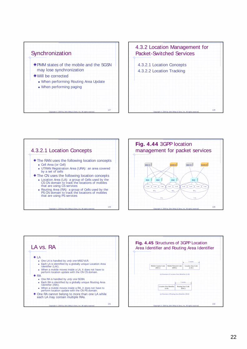
Initiated by the source BSCHandoff Required: carry information to indicate that the requested handoff is for packet-switched services and is an inter-PCF hard handoff PDSN IP Address Protocol Type: identifies the Link-Layer protocol used at the
mobile and its serving PDSN to exchange user IP packetsA11 Registration Request As discussed in Chapter 2, the A11 Registration Request
uses the same format as the MIPv4 Registration Request (Figure 4.12). Care-of Address field: set to the IP address of the target PCF Home Agent field: set to the IP address of the PDSN Home Address field: set to zero to indicate that the requested
A10 connection is for supporting an intra-PDSN handoff
4.4.3.3 Regular Inter-PDSN Hard Handoff for Active Mobiles
No P-P interface is implemented between the mobile’s serving PDSN and the target PDSN.The target PCF will have to select a target PDSN for each mobile that is performing inter-PDSN handoff. How to determine which PDSN should be the target PDSN
for a mobile is an implementation issue.The target PDSN becomes the mobile’s new serving PDSN after the handoff. The mobile needs to establish a new PPP connection to the
target PDSN during the handoff process. The mobile has to use a new care-of address after it is
handed off to the target PDSN. The mobile will need to perform Mobile IP registration.
4.4.3.4 Inter-PCF Dormant Handoff within the Same PDSN
Initiated by a mobileMay be performed when the mobile detects a change of the Packet Zone ID (PZID), Network ID (NID) or System ID (SID) When triggered by a change of PZID, it also serves the purpose of
Packet Zone update.The main task is to establish a new A10 connection between the target PCF and the PDSN.The A11 Registration Reply message to the target PCF carries an indication to inform the target PCF whether the PDSN has user data to send to the mobile at the moment. If the PDSN has no user data to send to the mobile: The target PCF
will reply to the target BSC with an A9-Release-A8 Complete message.
If the PDSN has user data to send to the mobile: The target PCF will reply to the target BSC with an A9-Connect-A8 message.
Assignment Failure: carry a Failure Cause value indicating Packet Call Going Dormant rather than any real failure
Can only be supported when a mobile is in ACTIVE stateThe mobile’s serving PDSN remains unchanged as long as the mobile’s Packet Data Service State remains in ACTIVE state.The mobile does not renegotiate its PPP connection.
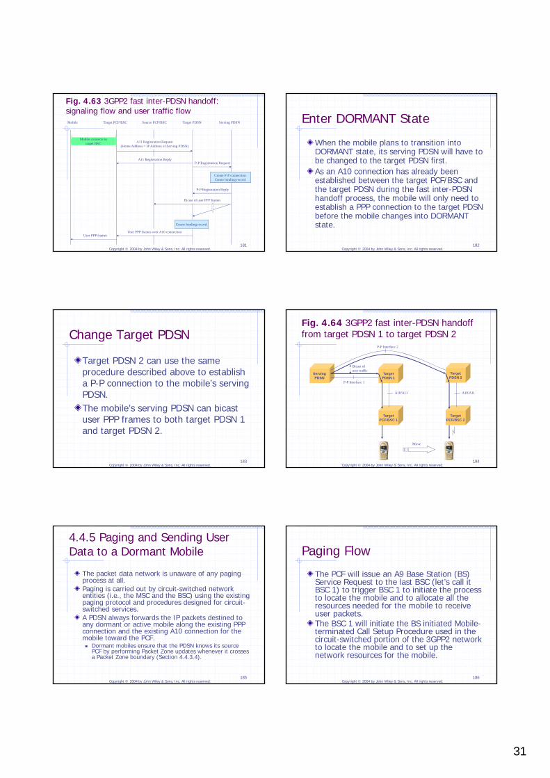
When the mobile plans to transition into DORMANT state, its serving PDSN will have to be changed to the target PDSN first.As an A10 connection has already been established between the target PCF/BSC and the target PDSN during the fast inter-PDSN handoff process, the mobile will only need to establish a PPP connection to the target PDSN before the mobile changes into DORMANT state.
Target PDSN 2 can use the same procedure described above to establish a P-P connection to the mobile’s serving PDSN. The mobile’s serving PDSN can bicast user PPP frames to both target PDSN 1 and target PDSN 2.
4.4.5 Paging and Sending User Data to a Dormant Mobile
The packet data network is unaware of any paging process at all.Paging is carried out by circuit-switched network entities (i.e., the MSC and the BSC) using the existing paging protocol and procedures designed for circuit-switched services.A PDSN always forwards the IP packets destined to any dormant or active mobile along the existing PPP connection and the existing A10 connection for the mobile toward the PCF. Dormant mobiles ensure that the PDSN knows its source
PCF by performing Packet Zone updates whenever it crosses a Packet Zone boundary (Section 4.4.3.4).
The PCF will issue an A9 Base Station (BS) Service Request to the last BSC (let’s call it BSC 1) to trigger BSC 1 to initiate the process to locate the mobile and to allocate all the resources needed for the mobile to receive user packets.The BSC 1 will initiate the BS initiated Mobile-terminated Call Setup Procedure used in the circuit-switched portion of the 3GPP2 network to locate the mobile and to set up the network resources for the mobile.
Use IP-based protocols defined or being developed by the IETF to support mobilityMain functional entities for mobility management Mobile Attendant (MA) Home Mobility Manager (HMM) Home IP Address Manager IP Address Manager Location Server Geographical Location Manager (GLM) Global Name Server (GNS) Service Discovery Server
MWIF recommended IETF protocols for the interface references point between the mobility management functional entities.
4.6 Comparison of Mobility Management in IP, 3GPP, and 3GPP2 Networks
Similarity: They all use the Relayed Delivery strategy as the basic strategy for delivering packets to mobiles. In particular, a mobility anchor point is used for
tracking the mobile’s locations and for relaying packets to mobiles.
Differences The ways packets are transported from one
mobility protocol entity to another. Regular IP, IP-in-IP tunnel, GTP, GRE, etc.
How location management is related to route management. Regular IP routing, host-specific routing, etc.