Network Layer 4-1 Chapter 4 Network Layer Computer Networking: A Top Down Approach Featuring the Internet , 3 rd edition. Jim Kurose, Keith Ross Addison-Wesley, July 2004. A note on the use of these ppt slides: We’re making these slides freely available to all (faculty, students, readers). They’re in PowerPoint form so you can add, modify, and delete slides (including this one) and slide content to suit your needs. They obviously represent a lot of work on our part. In return for use, we only ask the following: q If you use these slides (e.g., in a class) in substantially unaltered form, that you mention their source (after all, we’d like people to use our book!) q If you post any slides in substantially unaltered form on a www site, that you note that they are adapted from (or perhaps identical to) our slides, and note our copyright of this material. Thanks and enjoy! JFK/KWR All material copyright 1996-2005 J.F Kurose and K.W. Ross, All Rights Reserved
Transcript
Network Layer 4-1
Chapter 4Network Layer
Computer Networking: A Top Down Approach Featuring the Internet, 3rd edition. Jim Kurose, Keith RossAddison-Wesley, July 2004.
A note on the use of these ppt slides:We’re making these slides freely available to all (faculty, students, readers). They’re in PowerPoint form so you can add, modify, and delete slides (including this one) and slide content to suit your needs. They obviously represent a lot of work on our part. In return for use, we only ask the following:q If you use these slides (e.g., in a class) in substantially unaltered form, that you mention their source (after all, we’d like people to use our book!)q If you post any slides in substantially unaltered form on a www site, that you note that they are adapted from (or perhaps identical to) our slides, and note our copyright of this material.
Thanks and enjoy! JFK/KWR
All material copyright 1996-2005J.F Kurose and K.W. Ross, All Rights Reserved
services:m network layer service modelsm forwarding versus routingm how a router worksm routing (path selection)m dealing with scalem advanced topics: IPv6, mobility
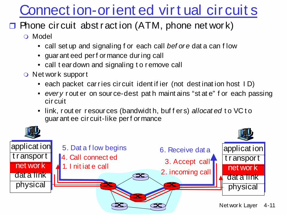
m Model• call setup and signaling for each call before data can flow• guaranteed performance during call• call teardown and signaling to remove call
m Network support• each packet carries circuit identifier (not destination host ID)• every router on source-dest path maintains “state” for each passing
circuit• link, router resources (bandwidth, buffers) allocated to VC to
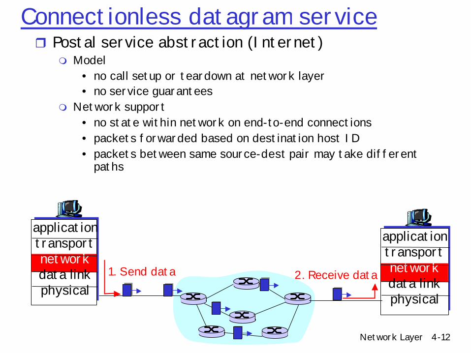
Connectionless datagram servicer Postal service abstraction (Internet)
m Model• no call setup or teardown at network layer• no service guarantees
m Network support• no state within network on end-to-end connections• packets forwarded based on destination host ID• packets between same source-dest pair may take different
paths
applicationtransportnetworkdata linkphysical
applicationtransportnetworkdata linkphysical
1. Send data 2. Receive data
Network Layer 4-13
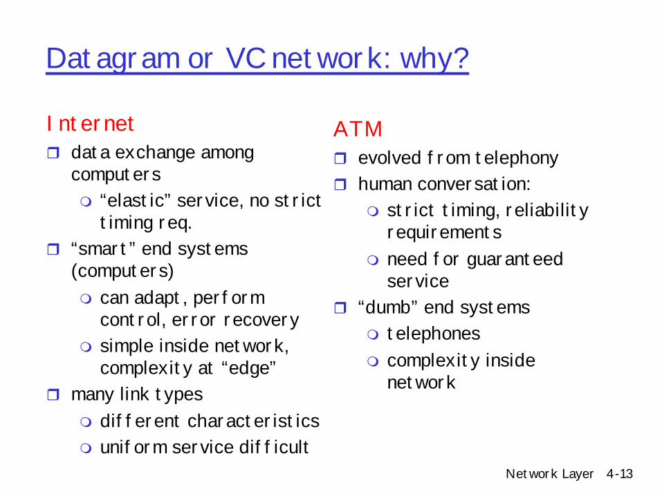
Datagram or VC network: why?
Internetr data exchange among
computersm “elastic” service, no strict
timing req. r “smart” end systems
(computers)m can adapt, perform
control, error recoverym simple inside network,
complexity at “edge”r many link types
m different characteristicsm uniform service difficult
ATMr evolved from telephonyr human conversation:
m strict timing, reliability requirements
m need for guaranteed service
r “dumb” end systemsm telephonesm complexity inside
network
Network Layer 4-14
Best of both worlds?• Adding circuits to the Internet
– Intserv, Diffserv (at the end of course if time permits)– Chapter 6 in book
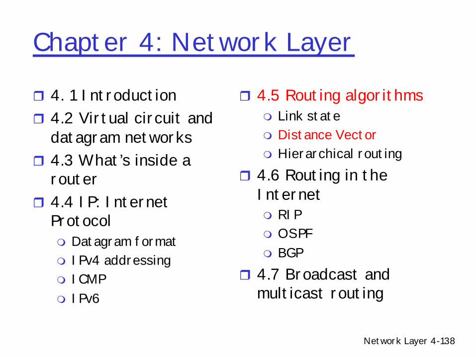
r 4.5 Routing algorithmsm Link statem Distance Vectorm Hierarchical routing
r 4.6 Routing in the Internetm RIPm OSPFm BGP
r 4.7 Broadcast and multicast routing
Network Layer 4-18
How is IP Design Standardized?r IETFm Voluntary organizationmMeeting every 4 monthsmWorking groups and email discussions
r “We reject kings, presidents, and voting; we believe in rough consensus and running code” (Dave Clark 1992)mNeed 2 independent, interoperable implementations
for standardr IRTFm End2End m Reliable Multicast, etc..
Network Layer 4-19
IP datagram format
ver length
32 bits
data (variable length,typically a TCP
or UDP segment)
16-bit identifierInternetchecksum
time tolive
32 bit source IP address
IP protocol versionnumber
header length(bytes)
max numberremaining hops
(decremented at each router)
forfragmentation/reassembly
total datagramlength (bytes)
upper layer protocolto deliver payload to
head.len
type ofservice
“type” of data flgs fragmentoffset
upperlayer
32 bit destination IP address
Options (if any) E.g. timestamp,record routetaken, specifylist of routers to visit.
how much overhead with TCP?
r 20 bytes of TCPr 20 bytes of IPr = 40 bytes + app
layer overhead
Network Layer 4-20
IP headerr Versionm Currently at 4, next version 6
rHeader lengthm Length of header (20 bytes plus options)
rType of Servicem Typically ignoredm Values
• 3 bits of precedence• 1 bit of delay requirements• 1 bit of throughput requirements• 1 bit of reliability requirements
m Replaced by DiffServ and ECNr Lengthm Length of IP fragment (payload)
Network Layer 4-21
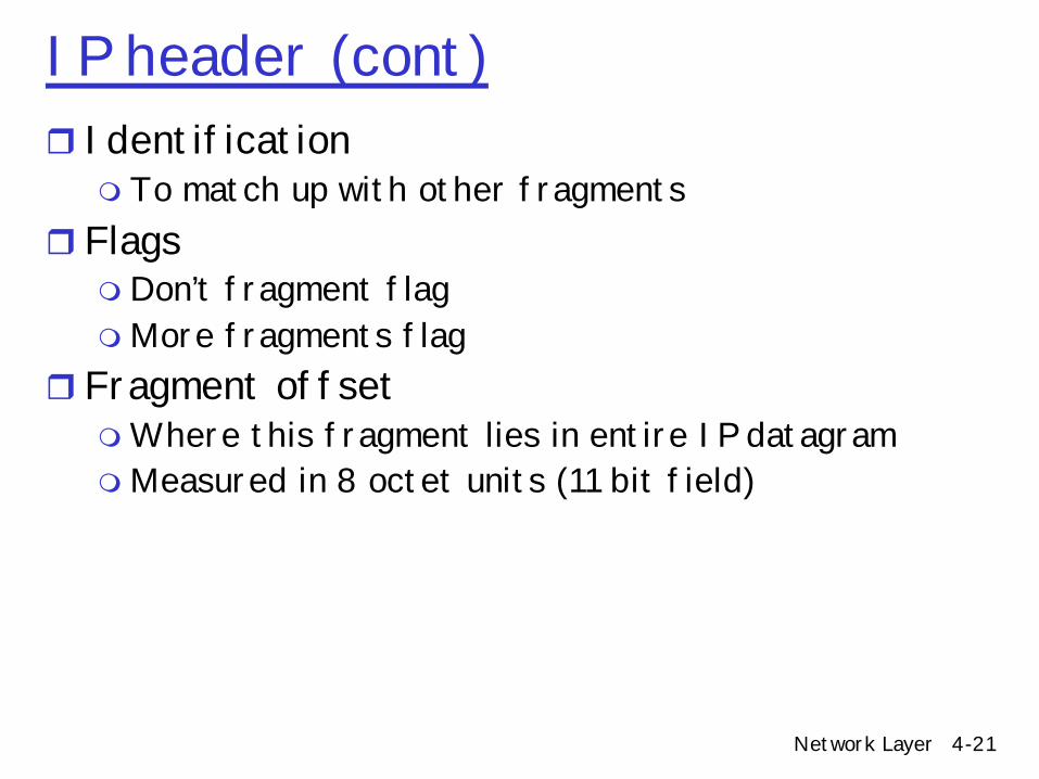
IP header (cont)r Identification m To match up with other fragments
r Flagsm Don’t fragment flagmMore fragments flag
r Fragment offsetmWhere this fragment lies in entire IP datagrammMeasured in 8 octet units (11 bit field)
Network Layer 4-22
IP header (cont)r Time to live
m Ensure packets exit the networkr Protocol
m Demultiplexing to higher layer protocolsr Header checksum
m Ensures some degree of header integritym Relatively weak – 16 bit
r Source IP, Destination IP (32 bit addresses)r Options
m E.g. Source routing, record route, etc.m Performance issues
• Poorly supported
Network Layer 4-23
IP quality of servicer IP originally had “type-of-service” (TOS) field to
eventually support qualitymNot used, ignored by most routers
rThen came int-serv (integrated services) and RSVP signallingm Per-flow quality of service through end-to-end
support• Setup and match flows on connection ID• Per-flow signaling• Per-flow network resource allocation (*FQ, *RR scheduling
algorithms)
Network Layer 4-24
IP quality of servicer RSVP
m http://www.rfc-editor.org/rfc/rfc2205.txtm Provides end-to-end signaling to network elementsm General purpose protocol for signaling informationm Not used now on a per-flow basis to support int-serv, but being
reused for diff-serv.r int-serv
m Defines service model (guaranteed, controlled-load)• http://www.rfc-editor.org/rfc/rfc2210.txt• http://www.rfc-editor.org/rfc/rfc2211.txt• http://www.rfc-editor.org/rfc/rfc2212.txt
m Dozens of scheduling algorithms to support these services• WFQ, W2FQ, STFQ, Virtual Clock, DRR, etc.• If this class was being given 5 years ago….
Network Layer 4-25
IP quality of servicerWhy did RSVP, int-serv fail?m Complexity
m Lack of scalability• Per-flow state• Route pinning
m Economics• Providers with no incentive to deploy• SLA, end-to-end billing issues
mQoS a weak-link property• Requires every device on an end-to-end basis to support flow
Network Layer 4-26
IP quality of servicerNow it’s diff-serv…m Use the “type-of-service” bits as a priority markingm http://www.rfc-editor.org/rfc/rfc2474.txtm http://www.rfc-editor.org/rfc/rfc2475.txtm http://www.rfc-editor.org/rfc/rfc2597.txtm http://www.rfc-editor.org/rfc/rfc2598.txtm Core network relatively statelessm AF
• Assured forwarding (drop precedence)m EF
• Expedited forwarding (strict priority handling)
Network Layer 4-27
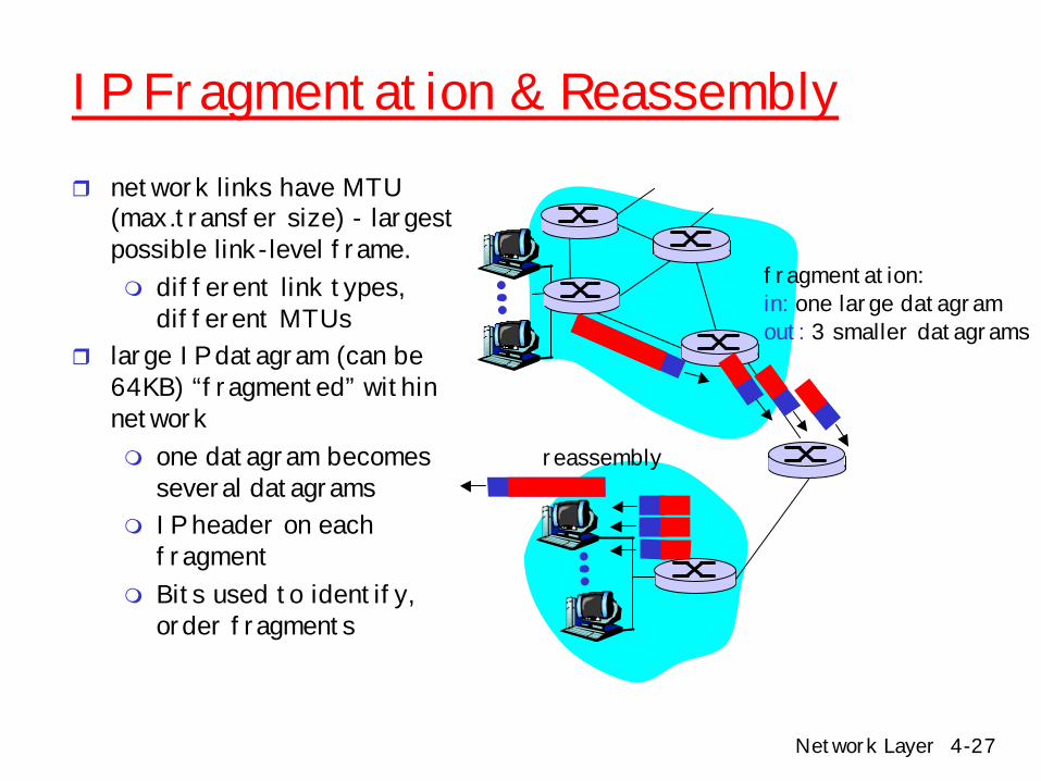
IP Fragmentation & Reassemblyr network links have MTU
(max.transfer size) - largest possible link-level frame.m different link types,
different MTUs r large IP datagram (can be
64KB) “fragmented” within networkm one datagram becomes
several datagramsm IP header on each
fragmentm Bits used to identify,
order fragments
fragmentation: in: one large datagramout: 3 smaller datagrams
reassembly
Network Layer 4-28
IP Fragmentation & Reassemblyr Where to do reassembly?
m End nodes• avoids unnecessary
workm Dangerous to do at
intermediate nodes• Buffer space• Must assume single
path through network• May be re-
fragmented later on in the route again
fragmentation: in: one large datagramout: 3 smaller datagrams
reassembly
Network Layer 4-29
IP Fragmentation and Reassembly
ID=x
offset=0
fragflag=0
length=4000
ID=x
offset=0
fragflag=1
length=1500
ID=x
offset=185
fragflag=1
length=1500
ID=x
offset=370
fragflag=0
length=1040
One large datagram becomesseveral smaller datagrams
Exampler 4000 byte
datagramr MTU = 1500 bytes
1480 bytes in data field
offset =1480/8
Network Layer 4-30
Fragmentation is Harmful
rUses resources poorlym Forwarding costs per packetm Best if we can send large chunks of datamWorst case: packet just bigger than MTU
r Poor end-to-end performancem Loss of a fragment makes other fragments
uselessr Reassembly is hardm Buffering constraints
Network Layer 4-31
Fragmentation
r Referencesm Characteristics of Fragmented IP Traffic on Internet
Links. Colleen Shannon, David Moore, and k claffy --CAIDA, UC San Diego. ACM SIGCOMM Internet Measurement Workshop 2001. http://www.aciri.org/vern/sigcomm-imeas-2001.program.html
– C. A. Kent and J. C. Mogul, "Fragmentation considered harmful," in Proceedings of the ACM Workshop on Frontiers in Computer Communications Technology, pp. 390--401, Aug. 1988.http://www.research.compaq.com/wrl/techreports/abstracts/87.3.html
Network Layer 4-32
Fragmentation
r Path MTU Discoverym Remove fragmentation from the networkm Mandatory in IPv6
• Network layer does no fragmentationm Hosts dynamically discover minimum MTU of path
r 4.5 Routing algorithmsm Link statem Distance Vectorm Hierarchical routing
r 4.6 Routing in the Internetm RIPm OSPFm BGP
r 4.7 Broadcast and multicast routing
Network Layer 4-38
IP Addressingr IP address: fixed-
length, 32-bit identifier for host, router interfacem semantics getting fuzzy,
though (more later)
r interface: connection between host, router and physical linkm router’s typically have
multiple interfacesm host may have multiple
interfacesm IP addresses associated
with interface, not host, router
223.1.1.1
223.1.1.2
223.1.1.3
223.1.1.4 223.1.2.9
223.1.2.2
223.1.2.1
223.1.3.2223.1.3.1
223.1.3.27
223.1.1.1 = 11011111 00000001 00000001 00000001
223 1 11
Network Layer 4-39
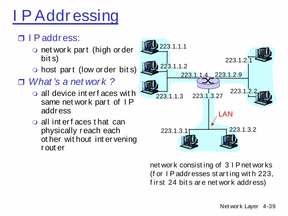
IP Addressingr IP address:
m network part (high order bits)
m host part (low order bits) r What’s a network ?
m all device interfaces with same network part of IP address
m all interfaces that can physically reach each other without intervening router
223.1.1.1
223.1.1.2
223.1.1.3
223.1.1.4 223.1.2.9
223.1.2.2
223.1.2.1
223.1.3.2223.1.3.1
223.1.3.27
network consisting of 3 IP networks(for IP addresses starting with 223, first 24 bits are network address)
LAN
Network Layer 4-40
Subnets 223.1.1.0/24223.1.2.0/24
223.1.3.0/24
How to find the networks (subnets)?
r Detach each interface from router, host
r create “islands of isolated networks
r Each isolated network is called a subnet
Subnet mask: /24
Network Layer 4-41
SubnetsHow many? 223.1.1.1
223.1.1.3
223.1.1.4
223.1.2.2223.1.2.1
223.1.2.6
223.1.3.2223.1.3.1
223.1.3.27
223.1.1.2
223.1.7.0
223.1.7.1223.1.8.0223.1.8.1
223.1.9.1
223.1.9.2
Network Layer 4-42
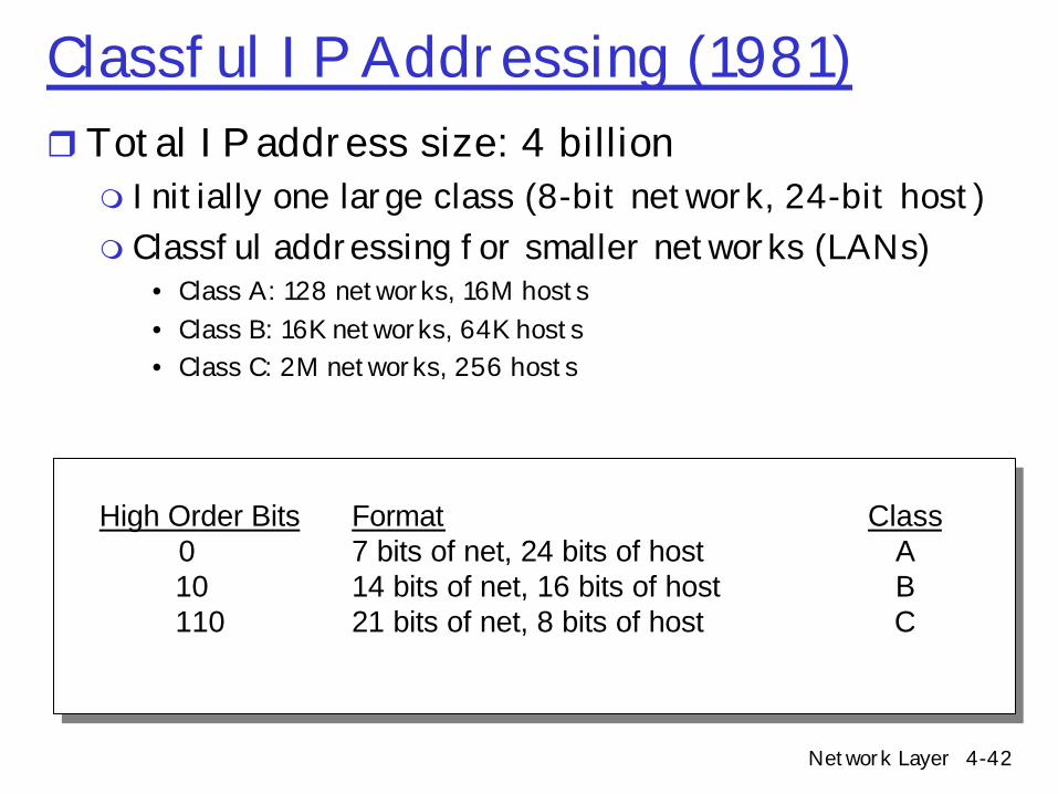
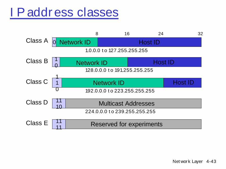
Classful IP Addressing (1981)rTotal IP address size: 4 billionm Initially one large class (8-bit network, 24-bit host)m Classful addressing for smaller networks (LANs)
• Class A: 128 networks, 16M hosts• Class B: 16K networks, 64K hosts• Class C: 2M networks, 256 hosts
High Order Bits0 10 110
Format7 bits of net, 24 bits of host14 bits of net, 16 bits of host21 bits of net, 8 bits of host
ClassABC
Network Layer 4-43
IP address classes
Network ID Host ID8 16
Class A32
0
Class B 10
Class C110
Multicast AddressesClass D 1110
Reserved for experimentsClass E 1111
24
Network ID
Network ID
Host ID
Host ID
1.0.0.0 to 127.255.255.255
128.0.0.0 to 191.255.255.255
192.0.0.0 to 223.255.255.255
224.0.0.0 to 239.255.255.255
Network Layer 4-44
Special IP Addressesr Private addresses
– http://www.rfc-editor.org/rfc/rfc1918.txt– Class A: 10.0.0.0 - 10.255.255.255 (10/8 prefix)– Class B: 172.16.0.0 - 172.31.255.255 (172.16/12 prefix)– Class C: 192.168.0.0 - 192.168.255.255 (192.168/16 prefix)
r 127.0.0.1: local host (a.k.a. the loopback address)r 255.255.255.255
m IP broadcast to local hardware that must not be forwarded m http://www.rfc-editor.org/rfc/rfc919.txtm Same as network broadcast if no subnetting
• IP of network broadcast=NetworkID+(all 1’s for HostID)
r 0.0.0.0m IP address of unassigned host (BOOTP, ARP, DHCP)m Default route advertisement
Network Layer 4-45
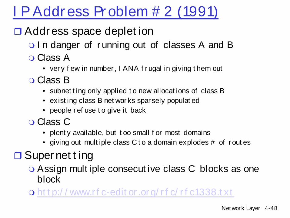
IP Addressing Problem #1 (1984)r Inefficient use of address space
m Class A (rarely given out, not many of them given out by IANA)m Class B = 64k hosts
• Very few LANs have close to 64K hosts• Electrical/LAN limitations, performance or administrative reasons • e.g., class B net allocated enough addresses for 64K hosts, even if only 2K
hosts in that networkm Need simple/address-efficient way to get multiple “networks”
• Reduce the total number of addresses that are assigned, but not used
r Subnet addressingm http://www.rfc-editor.org/rfc/rfc917.txtm Split up single large network address ranges into multiple smaller ones
(subnet)
Network Layer 4-46
Subnettingr Variable length subnet masks m Subnet a class B address space into several chunks
Network Host
Network HostSubnet
1111.. 00000000..1111 Mask
Network Layer 4-47
Subnetting ExamplerAssume an organization was assigned address
150.100rAssume < 100 hosts per subnet
m How many host bits do we need? Sevenm What is the network mask?
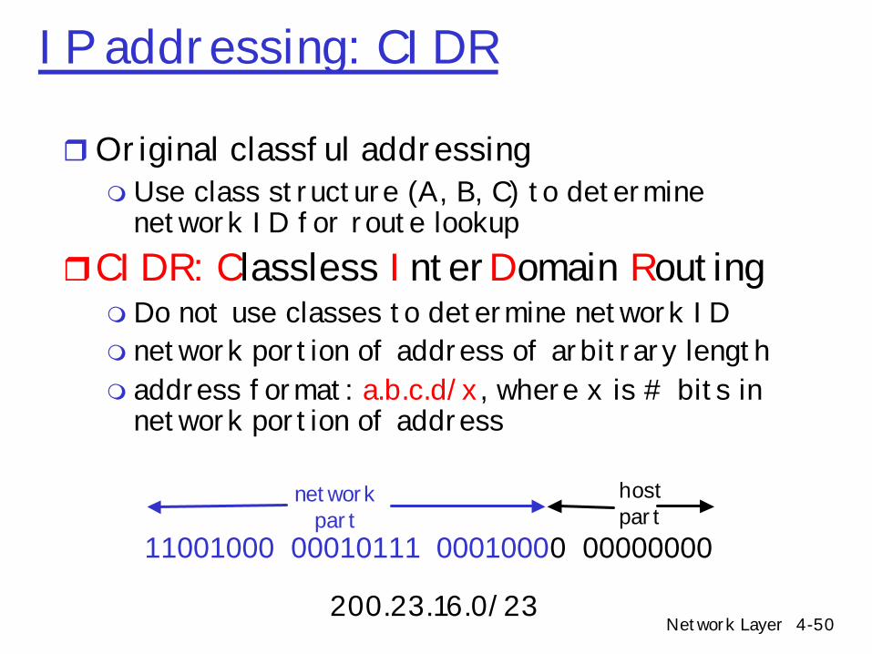
rOriginal classful addressingm Use class structure (A, B, C) to determine
network ID for route lookuprCIDR: Classless InterDomain Routingm Do not use classes to determine network IDm network portion of address of arbitrary lengthm address format: a.b.c.d/x, where x is # bits in
network portion of address
11001000 00010111 00010000 00000000
networkpart
hostpart
200.23.16.0/23
Network Layer 4-51
CIDR
rAssign any range of addresses to networkm Use common part of address as network numberm e.g., addresses 192.4.16.* to 192.4.31.* have the
first 20 bits in common. Thus, we use this as the network number
m netmask is /20, /xx is valid for almost any xxm 192.4.16.0/20
r Enables more efficient usage of address space (and router tables)
rMore on how this impacts routing later….
Network Layer 4-52
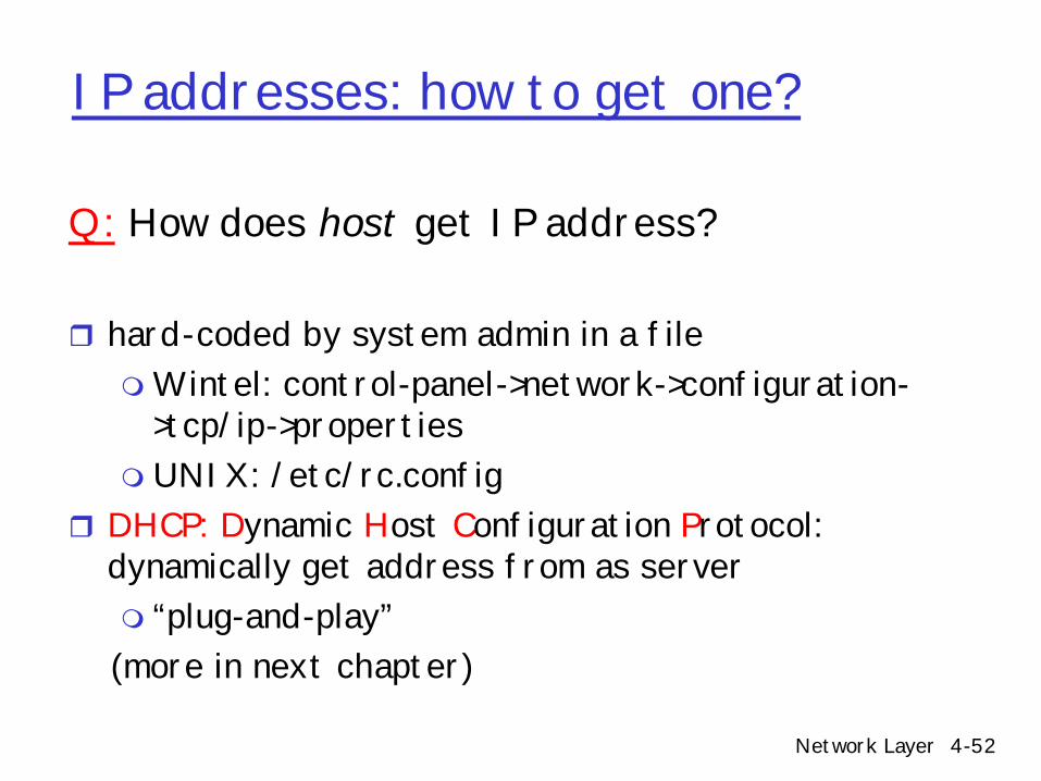
IP addresses: how to get one?
Q: How does host get IP address?
r hard-coded by system admin in a filemWintel: control-panel->network->configuration-
>tcp/ip->propertiesm UNIX: /etc/rc.config
r DHCP: Dynamic Host Configuration Protocol: dynamically get address from as serverm “plug-and-play” (more in next chapter)
Network Layer 4-53
IP addresses: how to get one?Q: How does network get subnet part of IP addr?A: organization gets allocated portion of its provider
ISP’s address spacem ISPs get it from ICANN: Internet Corporation for
Assigned Names and Numbers• Allocates addresses, manages DNS, resolves disputes
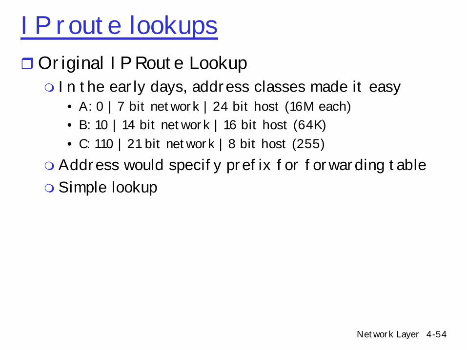
IP route lookupsrOriginal IP Route Lookup m In the early days, address classes made it easy
• A: 0 | 7 bit network | 24 bit host (16M each)• B: 10 | 14 bit network | 16 bit host (64K)• C: 110 | 21 bit network | 8 bit host (255)
m Address would specify prefix for forwarding tablem Simple lookup
Network Layer 4-55
Original IP Route Lookup – Examplerwww.pdx.edu address 131.252.120.50m Class B address – class + network is 131.252m Lookup 131.252 in forwarding tablem Prefix – part of address that really matters for
routingr Forwarding table containsm List of prefix entriesm A few fixed prefix lengths (8/16/24)
r Large tablesm 2 Million class C networksm Sites with multiple class C networks have multiple
route entries at every router
Network Layer 4-56
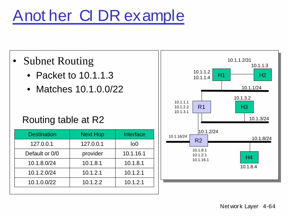
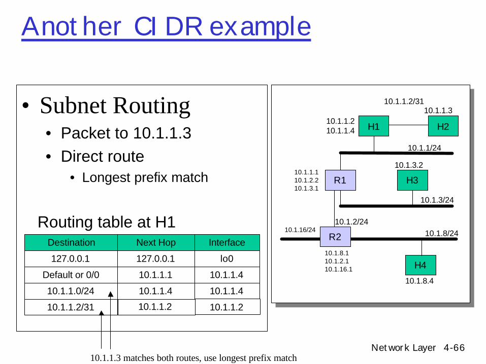
Getting a datagram from source to dest.
Classful routing example
IP datagram:
223.1.1.1
223.1.1.2
223.1.1.3
223.1.1.4 223.1.2.9
223.1.2.2
223.1.2.1
223.1.3.2223.1.3.1
223.1.3.27
A
BE
miscfields
sourceIP addr
destIP addr data
• datagram remains unchanged, as it travels source to destination
• addr fields of interest here
Dest. Net. next router Nhops
223.1.1 1223.1.2 223.1.1.4 2223.1.3 223.1.1.4 2
routing table in A
Network Layer 4-57
Getting a datagram from source to dest.
Starting at A, given IP datagram addressed to B:
r look up net. address of Br find B is on same net. as Ar link layer will send datagram
directly to B inside link-layer framem B and A are directly
connected
223.1.1.1
223.1.1.2
223.1.1.3
223.1.1.4 223.1.2.9
223.1.2.2
223.1.2.1
223.1.3.2223.1.3.1
223.1.3.27
A
BE
Dest. Net. next router Nhops
223.1.1 1223.1.2 223.1.1.4 2223.1.3 223.1.1.4 2
miscfields 223.1.1.1 223.1.1.3 data
Network Layer 4-58
Getting a datagram from source to dest.
Starting at A, dest. E:m look up network address of Em E on different network
• A, E not directly attachedm routing table: next hop router
to E is 223.1.1.4 m link layer sends datagram to
router 223.1.1.4 inside link-layer frame
m datagram arrives at 223.1.1.4 m continued…..
223.1.1.1
223.1.1.2
223.1.1.3
223.1.1.4 223.1.2.9
223.1.2.2
223.1.2.1
223.1.3.2223.1.3.1
223.1.3.27
A
BE
Dest. Net. next router Nhops
223.1.1 1223.1.2 223.1.1.4 2223.1.3 223.1.1.4 2
miscfields 223.1.1.1 223.1.2.2 data
Network Layer 4-59
Getting a datagram from source to dest.
223.1.1.1
223.1.1.2
223.1.1.3
223.1.1.4 223.1.2.9
223.1.2.2
223.1.2.1
223.1.3.2223.1.3.1
223.1.3.27
A
BE
miscfields 223.1.1.1 223.1.2.2 data network router Nhops interface
223.1.1 - 1 223.1.1.4223.1.2 - 1 223.1.2.9
223.1.3 - 1 223.1.3.27
Dest. next
Arriving at 223.1.4, destined for 223.1.2.2m look up network address of Em E on same network as router’s
interface 223.1.2.9• router, E directly attached
m link layer sends datagram to 223.1.2.2 inside link-layer frame via interface 223.1.2.9
m datagram arrives at 223.1.2.2!!!(hooray!)
Network Layer 4-60
IP route lookup and CIDRr Recall Classless routing (CIDR)
m Advantages• Saves space in route tables• Makes more efficient use of address space
– ISP allocated 8 class C chunks, 201.10.0.0 to 201.10.7.255– Allocation uses 3 bits of class C space– Remaining 21 bits are network number, written as 201.10.0.0/21– Replace 8 class C entries with 1 combined entry
• Routing protocols carry prefix length with destination network addressm But....Makes route lookup more complex
• No longer separate class A/B/C route tables each with O(1) lookup• One table containing many prefix lengths• Must match against all routes simultaneously via longest prefix match
Network Layer 4-61
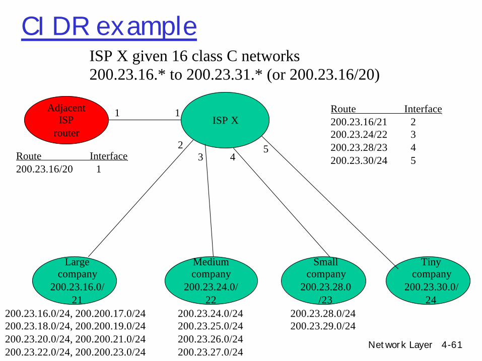
CIDR exampleISP X given 16 class C networks 200.23.16.* to 200.23.31.* (or 200.23.16/20)
rStride choicem Tuning stride to route tablem Bit shuffling
Network Layer 4-78
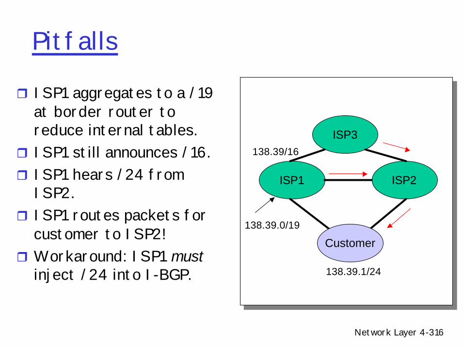
IP addressing and NATr Network Address Translation (NAT)
m Alternate solution to address space depletion problem• Kludge (but useful)
m Sits between your network and the Internetm Translates local, private, network layer addresses to global IP
addressesm Has a pool of global IP addresses (less than number of hosts on
your network)r What if we only have few (or just one) IP address?
m Use NAPT (Network Address Port Translator)m Both addresses and ports are translated
• Translates Paddr + flow info to Gaddr + new flow info• Uses TCP/UDP port numbers
m Potentially thousands of simultaneous connections with one global IP address
Network Layer 4-79
NAT Illustration
Global Internet
PrivateNetwork
Pool of global IP addresses
•Operation: Source (S) wants to talk to Destination (D):• Create Sg-Sp mapping• Replace Sp with Sg for outgoing packets• Replace Sg with Sp for incoming packets
PG
Dg Sp DataNAT
Destination Source
Dg Sg Data
Network Layer 4-80
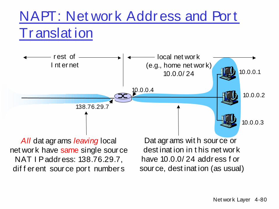
NAPT: Network Address and Port Translation
10.0.0.1
10.0.0.2
10.0.0.3
10.0.0.4
138.76.29.7
local network(e.g., home network)
10.0.0/24
rest ofInternet
Datagrams with source or destination in this networkhave 10.0.0/24 address for source, destination (as usual)
All datagrams leaving localnetwork have same single source
NAT IP address: 138.76.29.7,different source port numbers
Network Layer 4-81
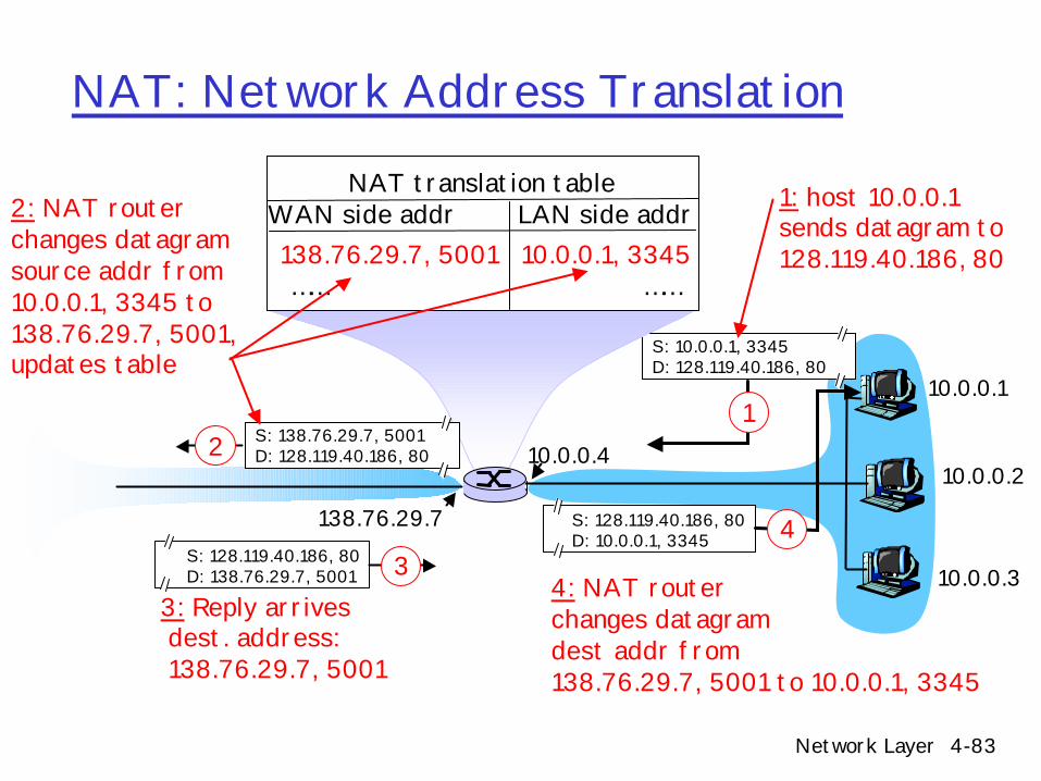
NAT: Network Address Translation
r Advantagesm range of addresses not needed from ISP: just a
small set of IP addresses for all devicesm can change addresses of devices in local network
without notifying outside worldm can change ISP without changing addresses of
devices in local networkm devices inside local net not explicitly addressable,
m outgoing datagrams: replace (source IP address, port #) of every outgoing datagram to (NAT IP address, new port #). . . remote clients/servers will respond using (NAT
IP address, new port #) as destination addr.
m remember (in NAT translation table) every (source IP address, port #) to (NAT IP address, new port #) translation pair
m incoming datagrams: replace (NAT IP address, new port #) in dest fields of every incoming datagram with corresponding (source IP address, port #) stored in NAT table
Network Layer 4-83
NAT: Network Address Translation
10.0.0.1
10.0.0.2
10.0.0.3
S: 10.0.0.1, 3345D: 128.119.40.186, 80
110.0.0.4
138.76.29.7
1: host 10.0.0.1 sends datagram to 128.119.40.186, 80
NAT translation tableWAN side addr LAN side addr138.76.29.7, 5001 10.0.0.1, 3345…… ……
r 4.5 Routing algorithmsm Link statem Distance Vectorm Hierarchical routing
r 4.6 Routing in the Internetm RIPm OSPFm BGP
r 4.7 Broadcast and multicast routing
Network Layer 4-87
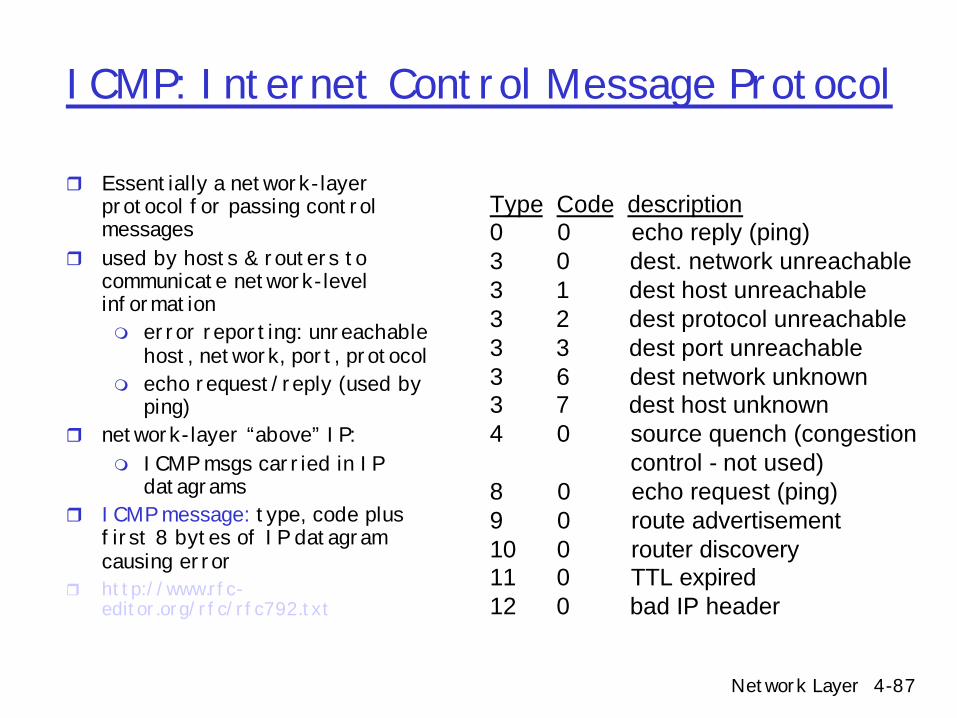
ICMP: Internet Control Message Protocol
r Essentially a network-layer protocol for passing control messages
r used by hosts & routers to communicate network-level informationm error reporting: unreachable
host, network, port, protocolm echo request/reply (used by
ping)r network-layer “above” IP:
m ICMP msgs carried in IP datagrams
r ICMP message: type, code plus first 8 bytes of IP datagram causing error
r http://www.rfc-editor.org/rfc/rfc792.txt
Type Code description0 0 echo reply (ping)3 0 dest. network unreachable3 1 dest host unreachable3 2 dest protocol unreachable3 3 dest port unreachable3 6 dest network unknown3 7 dest host unknown4 0 source quench (congestion
control - not used)8 0 echo request (ping)9 0 route advertisement10 0 router discovery11 0 TTL expired12 0 bad IP header
Network Layer 4-88
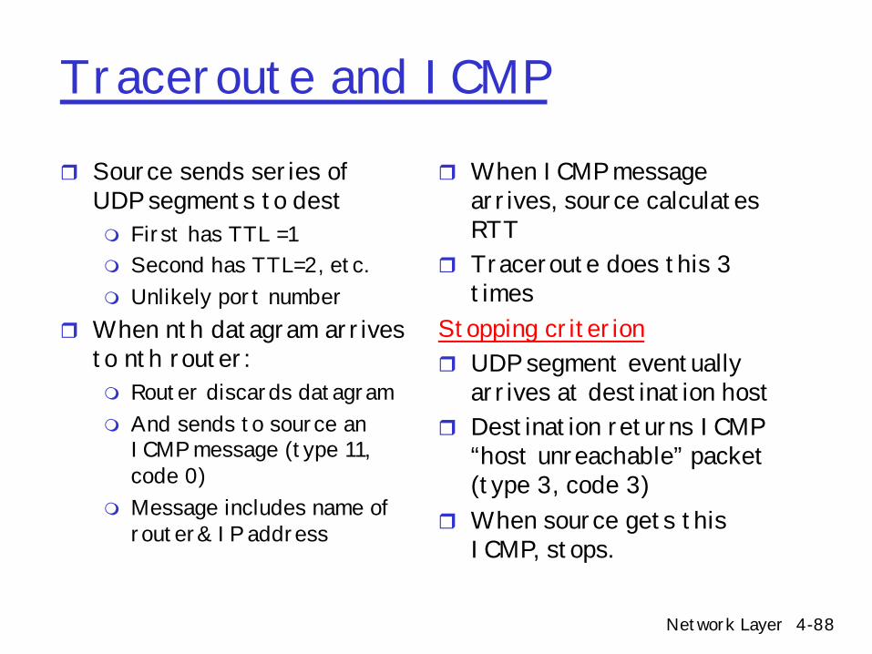
Traceroute and ICMP
r Source sends series of UDP segments to destm First has TTL =1m Second has TTL=2, etc.m Unlikely port number
r When nth datagram arrives to nth router:m Router discards datagramm And sends to source an
ICMP message (type 11, code 0)
m Message includes name of router& IP address
r When ICMP message arrives, source calculates RTT
r Traceroute does this 3 times
Stopping criterionr UDP segment eventually
arrives at destination hostr Destination returns ICMP
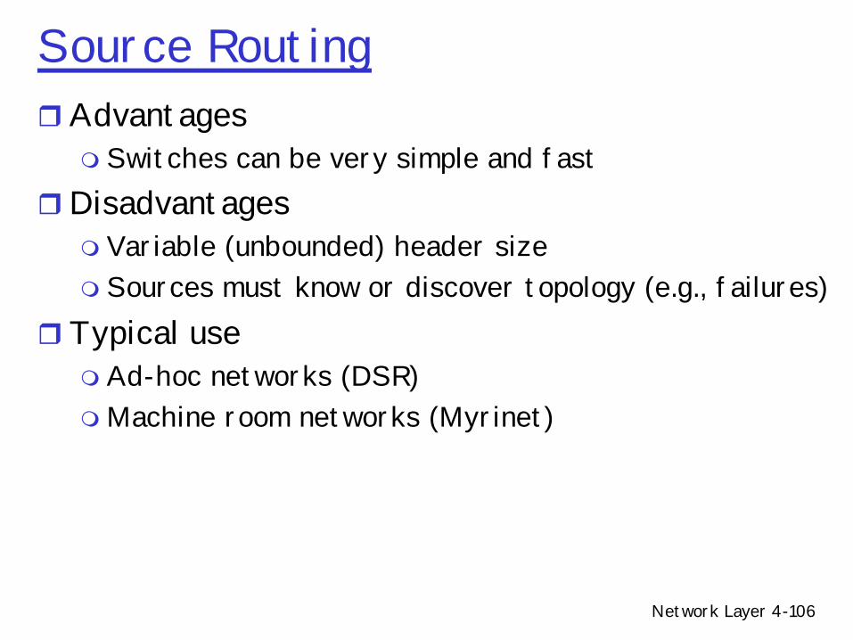
• Easier for hardware implementationsmMore flexible (different path for each flow)m Can reserve bandwidth at connection setup
rDisadvantagesm Still need to route connection setup requestmMore complex failure recovery – must recreate
connection staterTypical usesm ATM – combined with fix sized cellsmMPLS – tag switching for IP networks
Network Layer 4-110
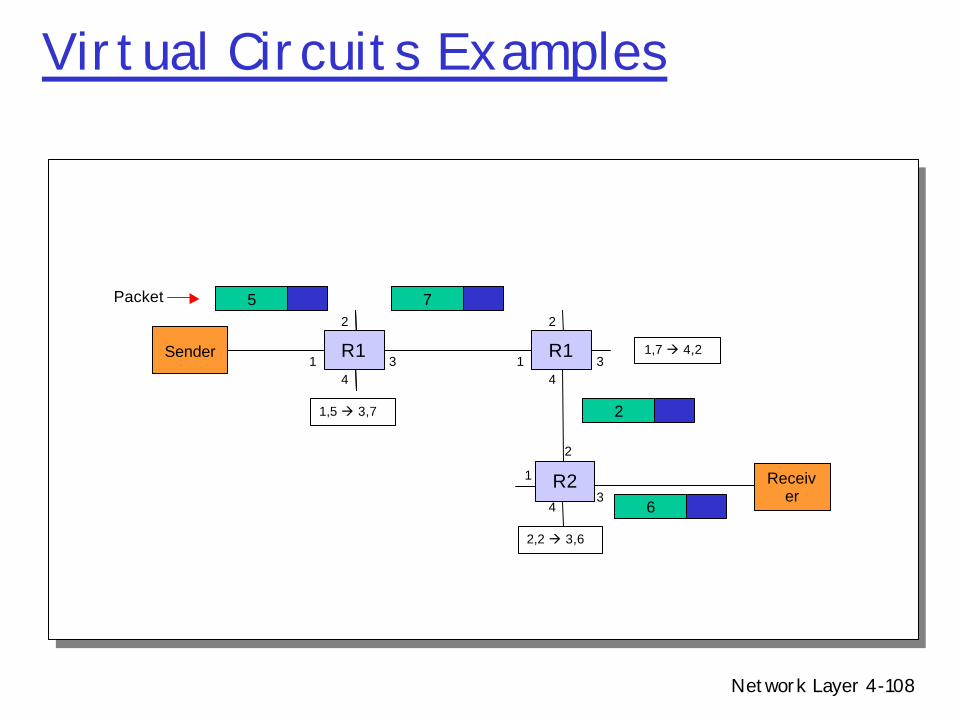
IP Datagrams on Virtual Circuitsr Challenge – when to setup connectionsm At bootup time – permanent virtual circuits (PVC)
• Large number of circuitsm For every packet transmission
• Connection setup is expensivem For every connection
• What is a connection?• How to route connectionless traffic?
m Based on traffic• VC for long-lived flows• Normal IP forwarding for all other flows
Network Layer 4-111
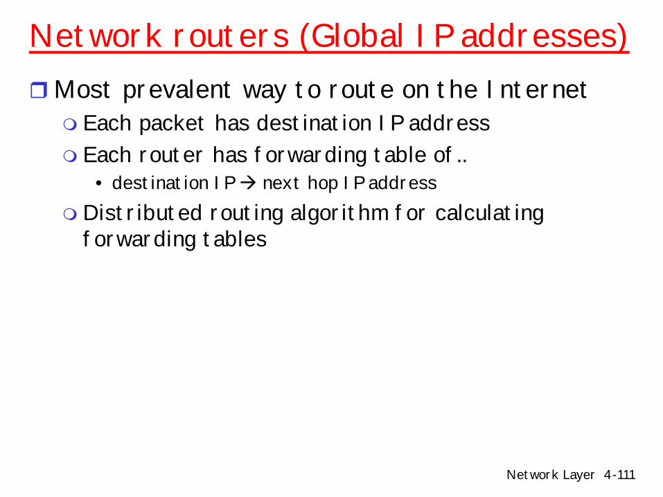
Network routers (Global IP addresses)rMost prevalent way to route on the Internetm Each packet has destination IP addressm Each router has forwarding table of..
• destination IP à next hop IP addressm Distributed routing algorithm for calculating
forwarding tables
Network Layer 4-112
Global Address Example
Receiver
Packet R
Sender
2
34
1
2
34
1
2
34
1
R2
R3
R1
R
RR à 3
R à 4
R à 3
R
Network Layer 4-113
Issues in Router Table SizerOne entry for every host on the Internetm 100M entries
rOne entry for every LANm Every host on LAN shares prefixm Still too many
rOne entry for every organizationm Every host in organization shares prefixm Requires careful address allocationmWhat constitutes an “organization”?
Network Layer 4-114
Global AddressesrAdvantagesm Simple error recovery
rDisadvantagesm Every router knows about every destination
• Potentially large tablesm All packets to destination take same route
Network Layer 4-115
Comparison
Source Routing Global Addresses
Header Size Worst OK – Large address
Router Table Size None Number of hosts (prefixes)
Forward Overhead Best Prefix matching
Virtual Circuits
OK (larger thanglobal if IP payload)
Number of circuits
Good (table index)
Setup Overhead None None
Error Recovery Tell all hosts Tell all routers
Connection Setup
Tell all routers, Tear down circuit
and re-route
Network Layer 4-116
u
yx
wv
z2
21
3
1
1
2
53
5
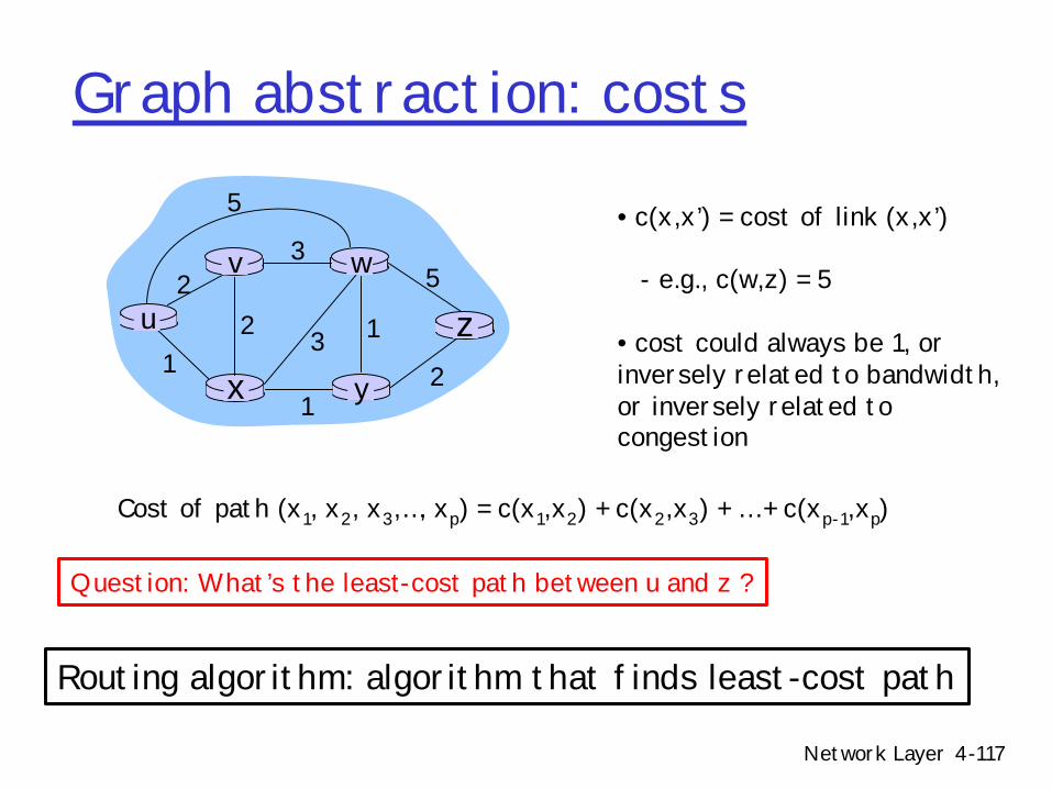
Graph: G = (N,E)
N = set of routers = { u, v, w, x, y, z }
E = set of links ={ (u,v), (u,x), (v,x), (v,w), (x,w), (x,y), (w,y), (w,z), (y,z) }
Graph abstraction
Remark: Graph abstraction is useful in other network contexts
Example: P2P, where N is set of peers and E is set of TCP connections
Network Layer 4-117
Graph abstraction: costs
u
yx
wv
z2
21
3
1
1
2
53
5 • c(x,x’) = cost of link (x,x’)
- e.g., c(w,z) = 5
• cost could always be 1, or inversely related to bandwidth,or inversely related to congestion
r 4.5 Routing algorithmsm Link statem Distance Vectorm Hierarchical routing
r 4.6 Routing in the Internetm RIPm OSPFm BGP
r 4.7 Broadcast and multicast routing
Network Layer 4-121
A Link-State Routing Algorithm
Dijkstra’s algorithmr net topology, link costs known to all nodesmaccomplished via “link state broadcast” mall nodes have same info
r computes least cost paths from one node (‘source”) to all other nodesmgives forwarding table for that nodem iterative: after k iterations, know least cost
path to k dest.’s
Network Layer 4-122
Dijkstra’s algorithmrStart conditionm Each node assumed to know state of links to its
neighborsrStep 1: Link state broadcastm Each node broadcasts its local link states to all other
nodesm Reliable flooding mechanism
rStep 2: Shortest-path tree calculationm Each node locally computes shortest paths to all
other nodes from global statem Dijkstra’s shortest path tree (SPT) algorithm
Network Layer 4-123
Link state broadcast
r Link State Packets (LSPs) to broadcast state to all nodes
r Periodically, each node creates a link state packet containing:mNode IDm List of neighbors and link costm Sequence numberm Time to live (TTL)mNode outputs LSP on all its links
Network Layer 4-124
Link state broadcast
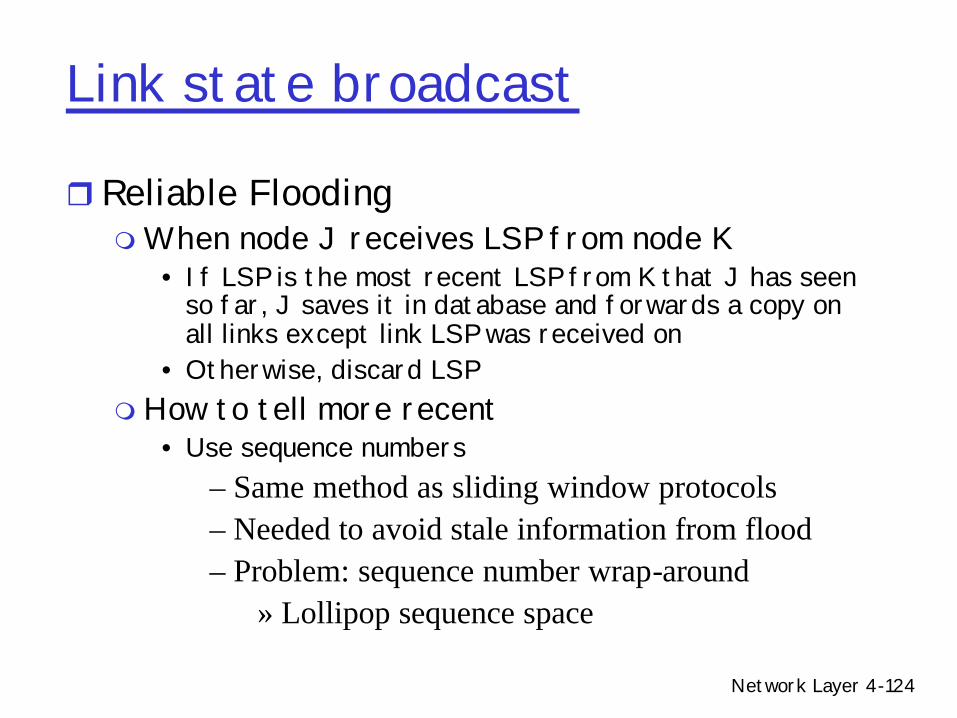
r Reliable Flooding mWhen node J receives LSP from node K
• If LSP is the most recent LSP from K that J has seen so far, J saves it in database and forwards a copy on all links except link LSP was received on
• Otherwise, discard LSPmHow to tell more recent
• Use sequence numbers– Same method as sliding window protocols– Needed to avoid stale information from flood– Problem: sequence number wrap-around
» Lollipop sequence space
Network Layer 4-125
Wrapped sequence numbers
rWrapped sequence numbersm 0-N where N is largem If difference between numbers is large, assume
a wrapm A is older than B if….
• A < B and |A-B| < N/2 or…• A > B and |A-B| > N/2
rWhat about new nodes or rebooted nodes that are out of sync with sequence number space?m Lollipop sequence (Perlman 1983)
Network Layer 4-126
Lollipop sequence numbers
r Divide sequence number spacer Special negative sequence for recovering from
rebootm New and rebooted nodes use negative sequence numbersm Upon receipt of negative number, other nodes inform
these nodes of current “up-to-date” sequence numberr A older than B if
m A < 0 and A < Bm A > 0, A < B and (B – A) < N/4m A > 0, A > B and (A – B) > N/4
0-N/2
N/2 - 1
Network Layer 4-127
Shortest-path tree calculation
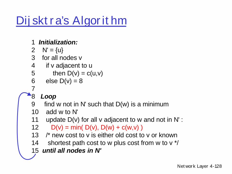
Notation:rc(x,y): link cost from node x to y; = 8 if
not direct neighborsrD(v): current value of cost of path from
source to dest. vrp(v): predecessor node along path from
source to vrN': set of nodes whose least cost path
definitively known
Network Layer 4-128
Dijsktra’s Algorithm1 Initialization:2 N' = {u} 3 for all nodes v 4 if v adjacent to u 5 then D(v) = c(u,v) 6 else D(v) = 87 8 Loop9 find w not in N' such that D(w) is a minimum 10 add w to N'11 update D(v) for all v adjacent to w and not in N' : 12 D(v) = min( D(v), D(w) + c(w,v) ) 13 /* new cost to v is either old cost to v or known 14 shortest path cost to w plus cost from w to v */ 15 until all nodes in N'
Network Layer 4-129
Shortest-path tree calculation(Dijkstra’s algorithm example)
A F
B
D E
C2
2
2
3
1
1
1
3
5
step SPT D(b), P(b) D(c), P(c) D(d), P(d) D(e), P(e) D(f), P(f)0 A 2, A 5, A 1, A ~ ~
5
B C D E F
D(v) = min( D(v), D(w) + c(w,v) )
Network Layer 4-130
Dijkstra’s algorithm example
A F
B
D E
C2
2
2
3
1
1
1
3
5
step SPT D(b), P(b) D(c), P(c) D(d), P(d) D(e), P(e) D(f), P(f)0 A 2, A 5, A 1, A ~ ~1 AD 2, A 4, D 2, D ~
5
B C D E F
D(v) = min( D(v), D(w) + c(w,v) )
Network Layer 4-131
Dijkstra’s algorithm example
A F
B
D E
C2
2
2
3
1
1
1
3
5
step SPT D(b), P(b) D(c), P(c) D(d), P(d) D(e), P(e) D(f), P(f)0 A 2, A 5, A 1, A ~ ~1 AD 2, A 4, D 2, D ~2 ADE 2, A 3, E 4, E
5
B C D E F
D(v) = min( D(v), D(w) + c(w,v) )
Network Layer 4-132
Dijkstra’s algorithm example
A F
B
D E
C2
2
2
3
1
1
1
3
5
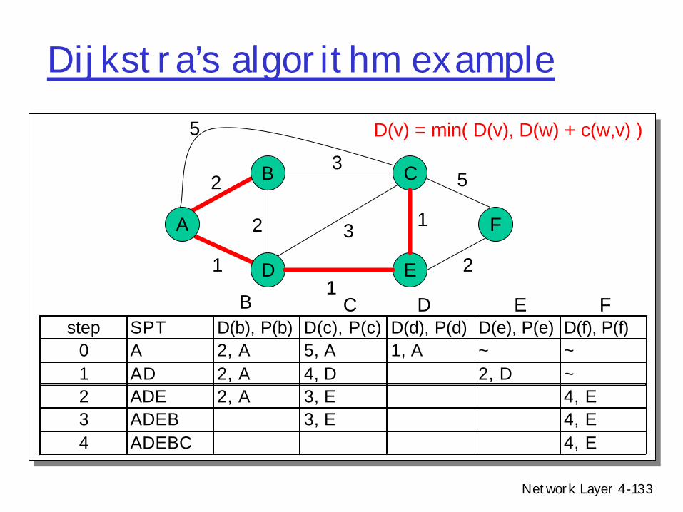
step SPT D(b), P(b) D(c), P(c) D(d), P(d) D(e), P(e) D(f), P(f)0 A 2, A 5, A 1, A ~ ~1 AD 2, A 4, D 2, D ~2 ADE 2, A 3, E 4, E3 ADEB 3, E 4, E
5
B C D E F
D(v) = min( D(v), D(w) + c(w,v) )
Network Layer 4-133
Dijkstra’s algorithm example
A F
B
D E
C2
2
2
3
1
1
1
3
5
step SPT D(b), P(b) D(c), P(c) D(d), P(d) D(e), P(e) D(f), P(f)0 A 2, A 5, A 1, A ~ ~1 AD 2, A 4, D 2, D ~2 ADE 2, A 3, E 4, E3 ADEB 3, E 4, E4 ADEBC 4, E
5
B C D E F
D(v) = min( D(v), D(w) + c(w,v) )
Network Layer 4-134
Dijkstra’s algorithm example
A F
B
D E
C2
2
2
3
1
1
1
3
5
step SPT D(b), P(b) D(c), P(c) D(d), P(d) D(e), P(e) D(f), P(f)0 A 2, A 5, A 1, A ~ ~1 AD 2, A 4, D 2, D ~2 ADE 2, A 3, E 4, E3 ADEB 3, E 4, E4 ADEBC 4, E5 ADEBCF
5
B C D E F
D(v) = min( D(v), D(w) + c(w,v) )
Network Layer 4-135
Dijkstra’s algorithm example
A
ED
CB
F
Resulting shortest-path tree from A:
BDECF
(A,B)(A,D)
(A,D)(A,D)(A,D)
destination link
Resulting forwarding table in A:
Network Layer 4-136
Link state algorithm characteristicsr Computation overhead
m n nodesm each iteration: need to check all
nodes, w, not in N• n*(n+1)/2 comparisons: O(n**2)• more efficient implementations
possible: O(n log(n)) r Space requirementsr Bandwidth requirementsr Stability
m Inconsistencies can cause transient loops
m Consistent LSDBs required for loop-free paths
A
B
C
D
1
3
5 2
1
Packet from CàAmay loop around BDCif B knows about failureand C & D do not
X
Network Layer 4-137
Link-state algorithm issuesOscillations possible:r e.g., link cost = amount of carried trafficr Example: path to A flaps as traffic routed clockwise
and counter-clockwiser Common problem in load-based link metrics
m A. Khanna and J. Zinky, "The Revised ARPANET Routing Metric," in ACM SIGCOMM, 1989, pp. 45--46.
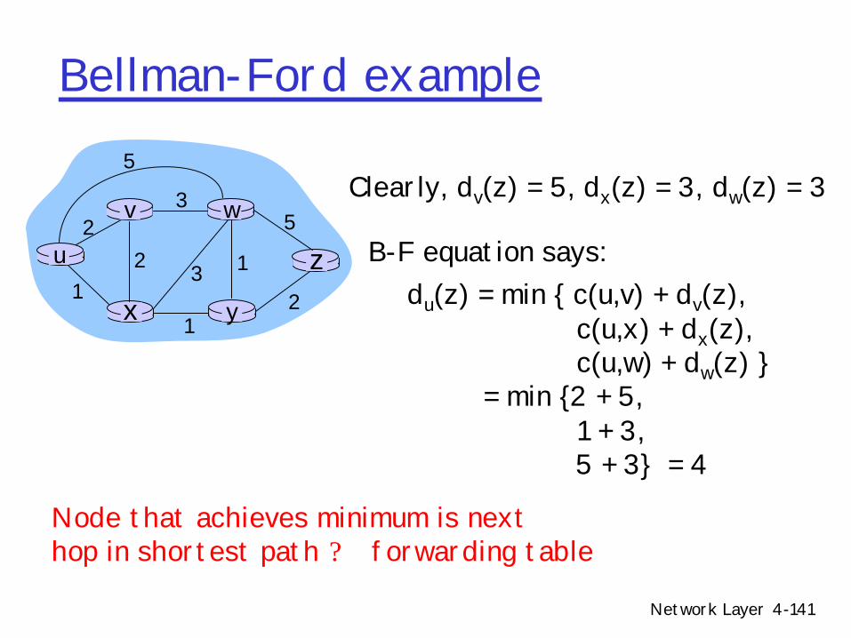
Node that achieves minimum is nexthop in shortest path ? forwarding table
B-F equation says:
Network Layer 4-142
Bellman algorithmr Update distance information iterativelyr Example (Bellman 1957)
m Start with link table (as with Dijkstra), calculate distance table iteratively
m Distance table data structure• table of known distances and next hops kept per node• row for each possible destination• column for each directly-attached neighbor to node• example: in node X, for dest. Y via neighbor Z:
Network Layer 4-143
Dj(k,*)
Bellman algorithmr Centralized version
i j
k
j’ k’
c(i,j)
c(i,j’)
Dj’(k,*)
Di(k,*)
For node i
while there is a change in D
for all k not neighbor of i
for each j neighbor of i
Di(k,j) = c(i,j) + Dj(k,*)if Di(k,j) < Di(k,*) {
Di(k,*) = Di(k,j)
Hi(k) = j
D (Y,Z)X
distance from X toY, via Z as next hop
c(X,Z) + min {D (Y,w)}Zw
=
=
D (Y,*)X
Minimum known distance from X to Y=
H (Y)X=
Next hop node from X to Y
Network Layer 4-144
Distance table example
A
E D
CB7
81
2
1
2D ()
A
B
C
D
A
1
7
6
4
B
14
8
9
11
D
5
5
4
2
Ecost to destination via
dest
inat
ion
D (C,D)E
c(E,D) + min {D (C,w)}Dw=
= 2+2 = 4
D (A,D)E
c(E,D) + min {D (A,w)}Dw=
= 2+3 = 5
D (A,B)E
c(E,B) + min {D (A,w)}Bw=
= 8+6 = 14
loop!
loop! H (Y) = X
Network Layer 4-145
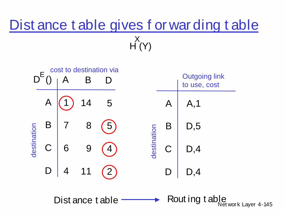
Distance table gives forwarding table
D ()
A
B
C
D
A
1
7
6
4
B
14
8
9
11
D
5
5
4
2
Ecost to destination via
dest
inat
ion
A
B
C
D
A,1
D,5
D,4
D,4
Outgoing link to use, cost
dest
inat
ion
Distance table Routing table
H (Y)X
Network Layer 4-146
Distributed Bellman-Ford
r Make Bellman algorithm distributed (Ford-Fulkerson 1962)m Each node i has distance vector estimates to other nodesm Iterate
• Each node sends around and recalculates D[i,*]• When a node x receives new DV estimate from neighbor, it updates its
own DV using B-F equation:
• If estimates change, broadcast entire table to neighbors– continues until no nodes exchange info.– self-terminating: no “signal” to stop
m D[i,*] eventually converges to shortest distance
Dx(y) ? minv{c(x,v) + Dv(y)} for each node y ? N
Network Layer 4-147
Distributed Bellman-Ford overview
Asynchronous:r “triggered updates”
m no need to exchange info/iterate in lock step!
Iterative:r When local link costs change r When neighbor sends a
message that its least cost path has changed for a node
Distributed:r nodes communicate only with
directly-attached neighborsr each node notifies neighbors
only when its least cost path to any destination changesm neighbors then notify their
neighbors if necessary
wait for (change in local link cost of msg from neighbor)
recompute distance table
if least cost path to any desthas changed, notifyneighbors
Each node:
Network Layer 4-148
Distributed Bellman-Ford algorithm
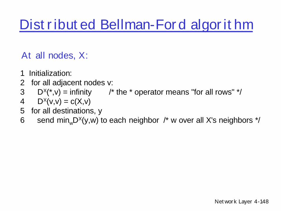
1 Initialization: 2 for all adjacent nodes v: 3 DX(*,v) = infinity /* the * operator means "for all rows" */ 4 DX(v,v) = c(X,v) 5 for all destinations, y 6 send minwDX(y,w) to each neighbor /* w over all X's neighbors */
At all nodes, X:
Network Layer 4-149
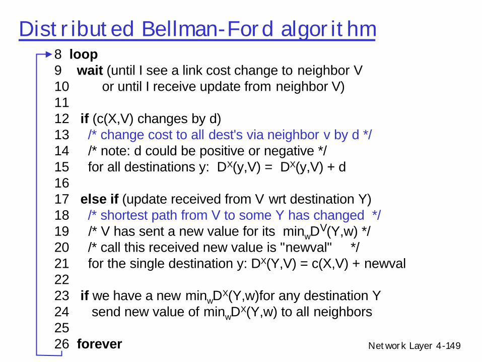
Distributed Bellman-Ford algorithm8 loop9 wait (until I see a link cost change to neighbor V 10 or until I receive update from neighbor V) 11 12 if (c(X,V) changes by d) 13 /* change cost to all dest's via neighbor v by d */14 /* note: d could be positive or negative */ 15 for all destinations y: DX(y,V) = DX(y,V) + d 16 17 else if (update received from V wrt destination Y) 18 /* shortest path from V to some Y has changed */19 /* V has sent a new value for its minwDV(Y,w) */ 20 /* call this received new value is "newval" */ 21 for the single destination y: DX(Y,V) = c(X,V) + newval 22 23 if we have a new minwDX(Y,w)for any destination Y 24 send new value of minwDX(Y,w) to all neighbors 25 26 forever
Network Layer 4-150
DBF example
A
B
E
C
D
Info atNode
A
B
C
D
A B C
0 7 ~
7 0 1
~ 1 0
~ ~ 2
7
1
1
2
28
Distance to Node
D
~
~
2
0
E 1 8 ~ 2
1
8
~
2
0
E
Initial Distance Vectors
Network Layer 4-151
DBF example
Info atNode
A
B
C
D
A B C
0 7 ~
7 0 1
~ 1 0
~ ~ 2
Distance to Node
D
~
~
2
0
E 1 8 4 2
1
8
~
2
0
E
A
B
E
C
D
7
1
1
2
28
E Receives D’s RoutesUpdates cost to C
Network Layer 4-152
DBF example
Info atNode
A
B
C
D
A B C
0 7 8
7 0 1
~ 1 0
~ ~ 2
Distance to Node
D
~
~
2
0
E 1 8 4 2
1
8
~
2
0
E
A
B
E
C
D
7
1
1
2
28
A receives B’s updateUpdates cost to C, but cost to E unchanged
Network Layer 4-153
DBF example
Info atNode
A
B
C
D
A B C
0 7 5
7 0 1
~ 1 0
~ ~ 2
Distance to Node
D
3
~
2
0
E 1 8 4 2
1
8
~
2
0
E
A
B
E
C
D
7
1
1
2
28
A receives E’s routesUpdates cost to C (new min) and D
Network Layer 4-154
DBF example
Info atNode
A
B
C
D
A B C
0 6 5
6 0 1
5 1 0
3 3 2
Distance to Node
D
3
3
2
0
E 1 5 4 2
1
5
4
2
0
E
A
B
E
C
D
7
1
1
2
28
And so on, until final distances....
Network Layer 4-155
DBF example
dest
A
B
C
D
A B D
1 14 5
7 8 5
6 9 4
4 11 2
Next hop
E’s routing table
A
B
E
C
D
7
1
1
2
28
E’s routing table
Network Layer 4-156
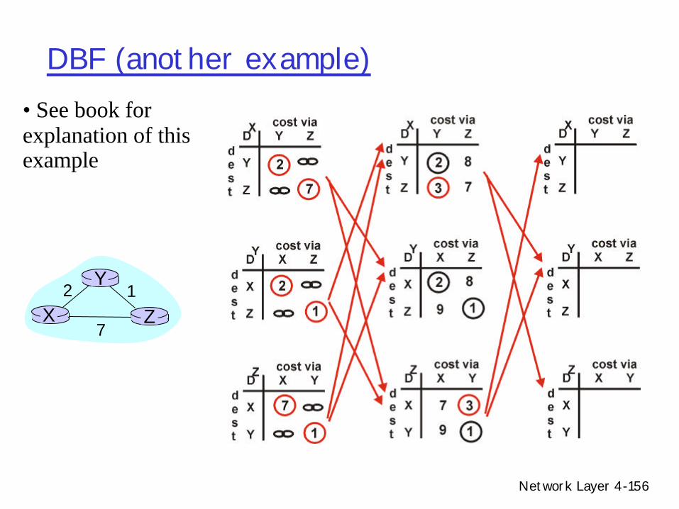
DBF (another example)
X Z12
7
Y
• See book for explanation of this example
Network Layer 4-157
DBF (another example)
X Z12
7
Y
D (Y,Z)X
c(X,Z) + min {D (Y,w)}w
=
= 7+1 = 8
Z
D (Z,Y)X
c(X,Y) + min {D (Z,w)}w=
= 2+1 = 3
Y
Network Layer 4-158
DBF (good news example)Link cost changes:• node detects local link cost change • updates distance table (line 15)• if cost change in least cost path, notify
neighbors (lines 23,24)• fast convergence (see book for details)
X Z14
50
Y1
algorithmterminates“good
news travelsfast”
Network Layer 4-159
DBF (good news example)
“goodnews travelsfast”
x z14
50
y1
At time t0, y detects the link-cost change, updates its DV, and informs its neighbors.
At time t1, z receives the update from y and updates its table. It computes a new least cost to x and sends its neighbors its DV.
At time t2, y receives z’s update and updates its distance table. y’s least costs do not change and hence y does not send any message to z.
Network Layer 4-160
DBF (count-to-infinity example)
Link cost changes:• good news travels fast • bad news travels slow - “count to infinity”
problem!• alternate route implicitly used link that
changed
X Z14
50
Y60
algorithmcontinues
on!
Network Layer 4-161
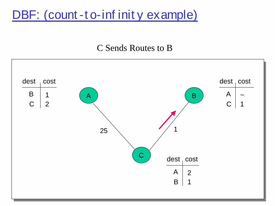
DBF: (count-to-infinity example)
A
25
1
1
B
C
BC 2
1
dest cost
AC 1
1
dest cost
AB 1
2
dest cost
X
Network Layer 4-162
DBF: (count-to-infinity example)
A
25 1
B
C
BC 2
1
dest cost
AC 1
~
dest cost
AB 1
2
dest cost
C Sends Routes to B
Network Layer 4-163
DBF: (count-to-infinity example)
A
25 1
B
C
BC 2
1
dest cost
AC 1
3
dest cost
AB 1
2
dest cost
B Updates Distance to A
Network Layer 4-164
DBF: (count-to-infinity example)
A
25 1
B
C
BC 2
1
dest cost
AC 1
3
dest cost
AB 1
4
dest cost
B Sends Routes to C
Network Layer 4-165
DBF: (count-to-infinity example)
A
25 1
B
C
BC 2
1
dest cost
AC 1
5
dest cost
AB 1
4
dest cost
C Sends Routes to B
Network Layer 4-166
Analyzing Distributed Bellman-Fordr Continuously send local distance tables of best
known routes to all neighbors until your table convergesm Computation diffuses until all nodes convergem Will computation converge quickly and deterministically?
• Not all the time, pathologic cases possible (count-to-infinity)
• Several algorithms for minimizing such cases
Network Layer 4-167
How are loops caused?rObservation 1:m B’s metric increases
rObservation 2:m C picks B as next hop to Am But, the implicit path from C to A includes itself!
Network Layer 4-168
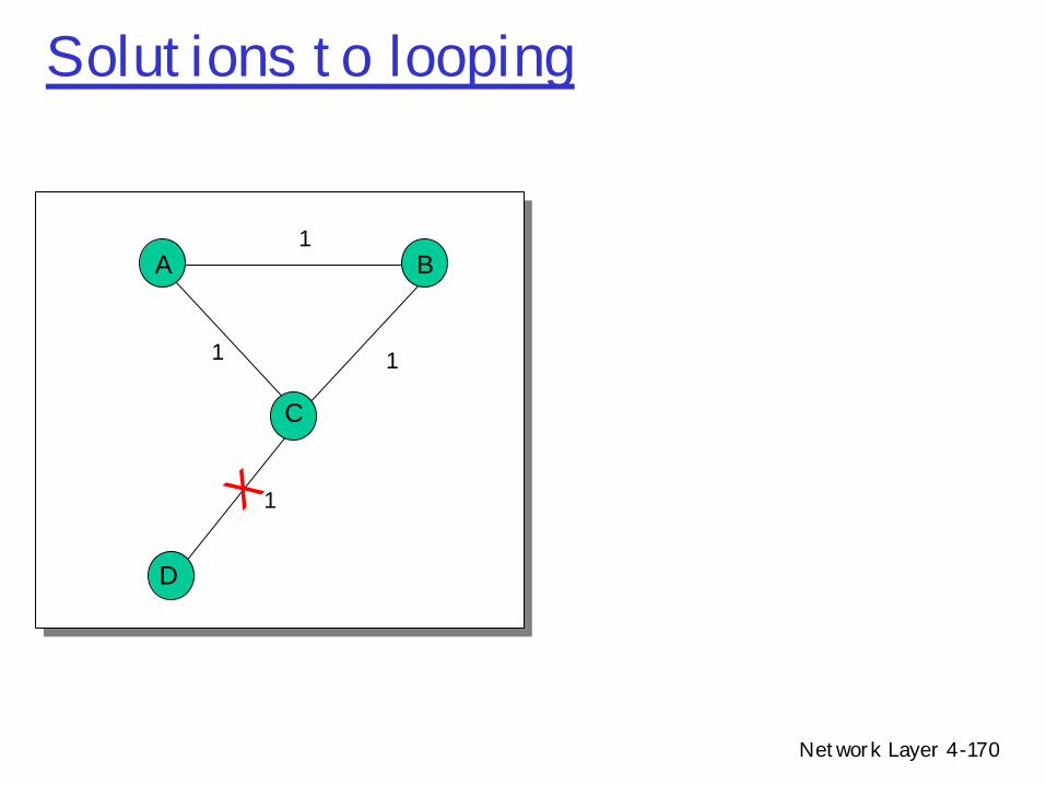
Solutions to loopingrSplit horizonm Do not advertise route to X to an adjacent neighbor if
your route to X goes through that neighborm If C routes through B to get to A, C does not
advertise (C=>A) route to B.r Poisoned reversem Advertise an infinite distance route to X to an
adjacent neighbor if your route to X goes through that neighbor
m If C routes through B to get to A, C advertises to B that its distance to A is infinity
rWorks for two node loopsm Does not work for loops with more nodes
Network Layer 4-169
Split-horizon with poisoned reverseIf Z routes through Y to get to X :• Z tells Y its (Z’s) distance to X is infinite (so
Y won’t route to X via Z)• will this completely solve count to infinity
problem? X Z
14
50
Y60
algorithmterminates
new route to X not involving Y
can now select and advertise route to X via Z
route to X through Y goes thru Zpoison it!
Network Layer 4-170
Solutions to looping
1
11
1
A
X
B
C
D
Network Layer 4-171
Solutions to loopingr Route poisoning
m Advertise infinite cost on a route to everyone (not just next hop) when lowest cost route increases
m Gets rid of stale information throughout networkm Used in conjunction with Path Holdown
r Path Holddownm Freeze route for a fixed time
• Do not switch to an alternate while route poisoning is happening• In our example, A and B delay changing and advertising new routes• A and B both set route to D to infinity after single step
m Configuring holddown delay• Delay too large: Slow convergence• Delay too small: Count-to-infinity more probable
Network Layer 4-172
Solutions to loopingr Path vector m Select loop-free pathsm Each route advertisement carries entire pathm If a router sees itself in path, it rejects the routem BGP does it this waym Space proportional to diameter of network
Network Layer 4-173
Solutions to loopingrDo solutions completely eliminate loops?mNo! Transient loops are still possiblemWhy? Because implicit path information may be stalem See this in BGP convergence
rOnly way to fix thism Ensure that you have up-to-date information by
explicitly querying
Network Layer 4-174
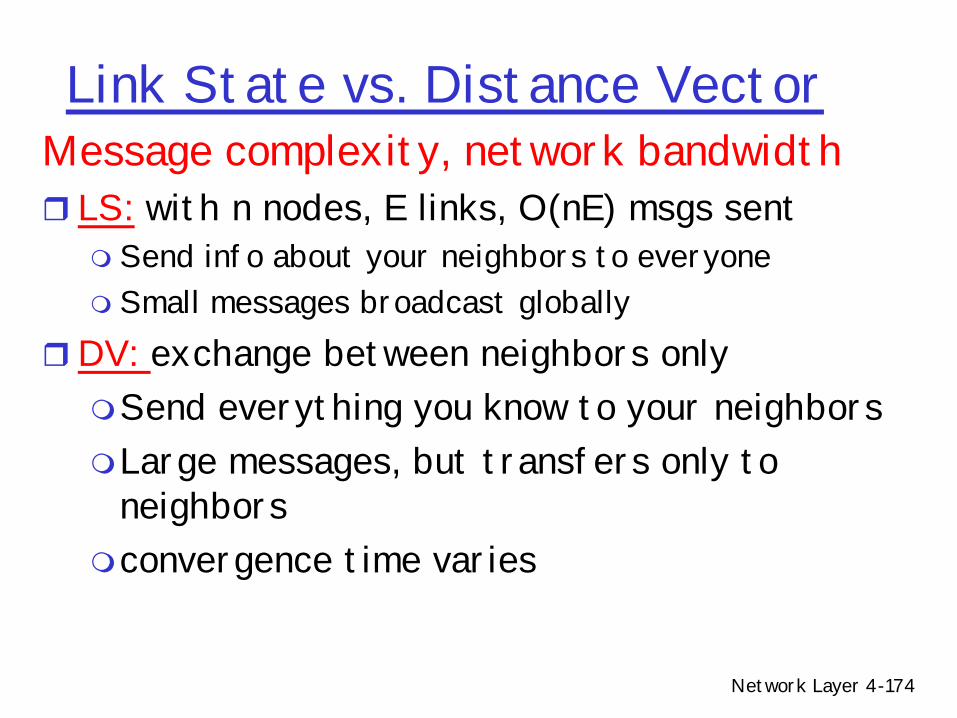
Message complexity, network bandwidthr LS: with n nodes, E links, O(nE) msgs sent m Send info about your neighbors to everyonem Small messages broadcast globally
rDV: exchange between neighbors onlymSend everything you know to your neighborsmLarge messages, but transfers only to
neighborsmconvergence time varies
Link State vs. Distance Vector
Network Layer 4-175
Link State vs. Distance VectorSpeed of Convergencer LS: O(n2) algorithm requires O(nE) msgsmFaster – can forward LSPs before processingmSingle SPT calculation
rDV: convergence time variesmFast with triggered updatesmcount-to-infinity problemmmay be routing loops
Network Layer 4-176
Link State vs. Distance VectorSpace requirements:r LS mmaintains entire topology
rDV mmaintains only neighbor statem path vector maintains routes proportional to network
diameter
Network Layer 4-177
Link State vs. Distance VectorRobustness:m LS can broadcast incorrect/corrupted LSP
• Can be made robust since sources are aware of alternate paths within topology
m DV can advertise incorrect paths to all destinations• Incorrect calculation can spread to entire network
Network Layer 4-178
DUALrDistributed Update Algorithm m Garcia-Luna-Aceves 1989m Goal: Avoid transient loops in DV and LS algorithms
• Similar in flavor to route poisoning and path holddownm 2 ideas
• A path shorter than current path cannot contain a loop• Based on diffusing computation (Dijkstra-Scholten 1980)
– Wait until computation completes before changing routes in response to a new update
– Similar to path-holddown
m 3 kinds of messages• Update, query, reply
m 2 states for routers• Active (queries outstanding), passive
Network Layer 4-179
DUALOn update if (lower cost) adoptelse if (higher cost) {
if (from next hop) {if (any path exists < old length from next hop)
switch pathelse
freeze routesend query to all neighbors except next hopgo into activewait for reply from all neighborsupdate routereturn to passive
r 4.5 Routing algorithmsm Link statem Distance Vectorm Hierarchical routing
r 4.6 Routing in the Internetm RIPm OSPFm BGP
r 4.7 Broadcast and multicast routing
Network Layer 4-181
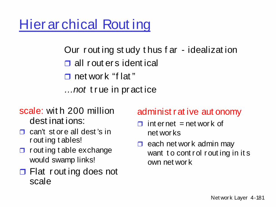
Hierarchical Routing
scale: with 200 million destinations:
r can’t store all dest’s in routing tables!
r routing table exchange would swamp links!
r Flat routing does not scale
administrative autonomyr internet = network of
networksr each network admin may
want to control routing in its own network
Our routing study thus far - idealization r all routers identicalr network “flat”… not true in practice
Network Layer 4-182
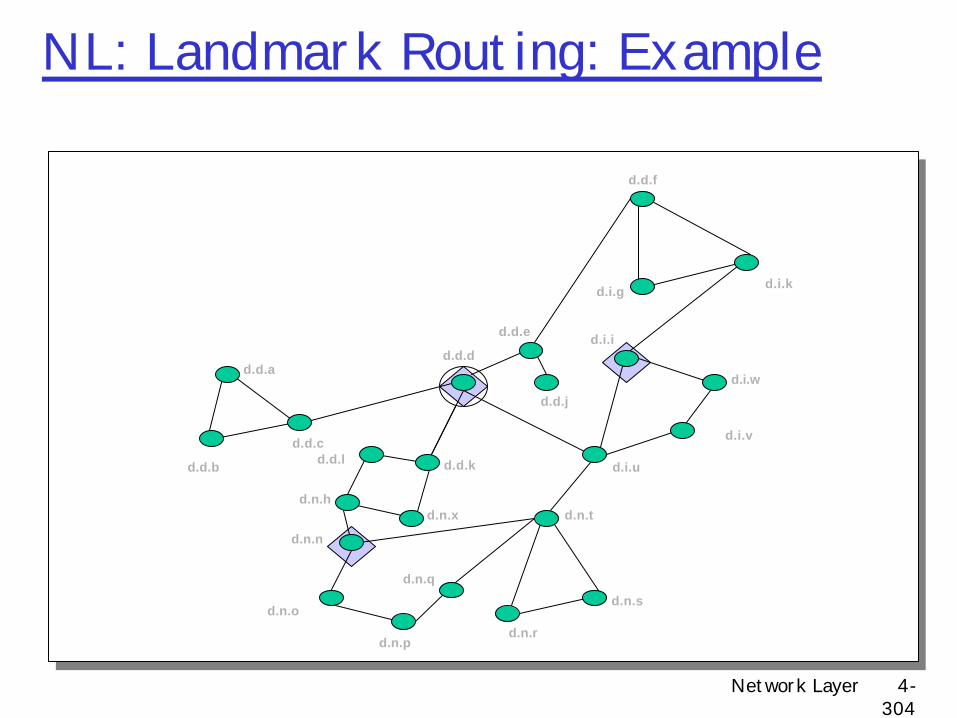
Routing Hierarchies
r Key observationmNeed less information with increasing distance to
destinationrTwo radically different approaches for routingm The area hierarchym The landmark hierarchy
• Covered in advanced topics at end of course...
Network Layer 4-183
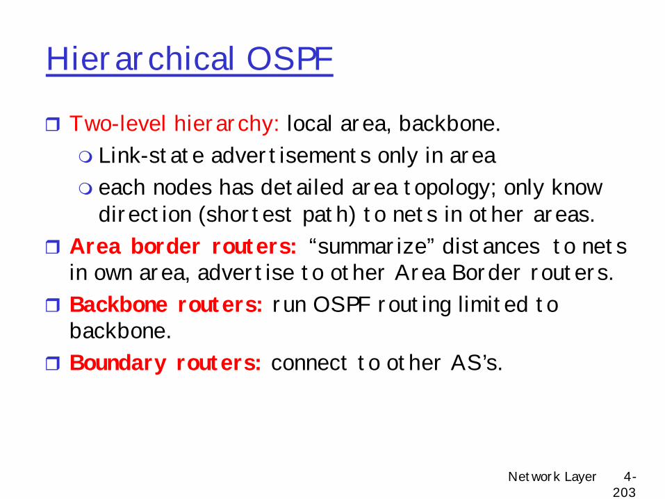
Areasr Divide network into areas
m Areas can have nested sub-areasm No path between two sub-areas of an area can exit that aream Within area, each node has routes to every other node m Outside area
• Each node has routes for other top-level areas only• Inter-area packets are routed to nearest appropriate border router• Can result in sub-optimal paths
r Hierarchically address nodes in a networkm Sequentially number top-level areasm Sub-areas of area are labeled relative to that aream Nodes are numbered relative to the smallest containing area
Network Layer 4-184
Hierarchical Routing on the Internet
r aggregate routers into regions, “autonomous systems” (AS)m administrative
autonomyr routers in same AS run
same routing protocolm “intra-AS” routing
protocol (IGP)m routers in different AS
can run different intra-AS routing protocol
Gateway routerm Direct link to router in
another ASm special routers in ASm run intra-AS routing
protocol with all other routers in AS
m also responsible for routing to destinations outside AS
m run inter-AS routing protocol or exterior gateway protocol (EGP) with other gateway routers in other AS’s
Network Layer 4-185
Example #1
1 2
3
1.11.2
2.1 2.2
3.1 3.2
2.2.1
44.1 4.2
5
5.1 5.2
EGP
IGP
EGPEGP
IGP
IGP
IGPIGP
EGPEGP
Network Layer 4-186
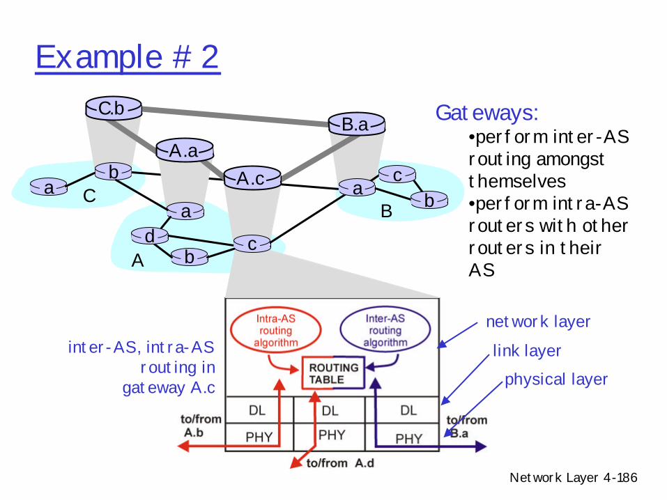
Example #2Gateways:
•perform inter-AS routing amongst themselves•perform intra-AS routers with other routers in their AS
inter-AS, intra-AS routing in
gateway A.c
network layer
link layerphysical layer
a
b
b
aaC
A
Bd
A.aA.c
C.bB.a
cb
c
Network Layer 4-187
Path Sub-optimality
1 2
3
1.11.2
2.1 2.2
3.1 3.2
2.2.1
3 hop red pathvs.2 hop green path
startend
3.2.1
1.2.1
Network Layer 4-188
AS CategoriesrStub: an AS that has only a single connection to
one other AS - carries only local traffic.rMulti-homed: an AS that has connections to
more than one AS, but does not carry transit traffic
rTransit: an AS that has connections to more than one AS, and carries both transit and local traffic (under certain policy restrictions)
r 4.5 Routing algorithmsm Link statem Distance Vectorm Hierarchical routing
r 4.6 Routing in the Internetm RIPm OSPFm BGP
r 4.7 Broadcast and multicast routing
Network Layer 4-193
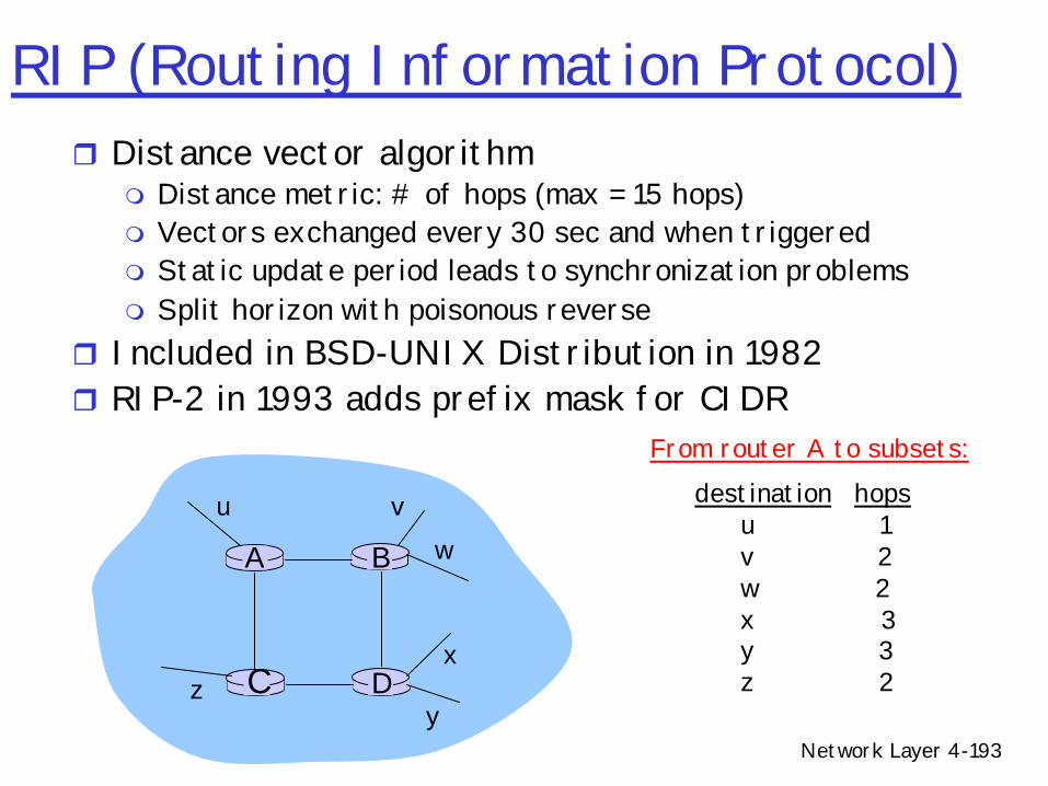
RIP (Routing Information Protocol)r Distance vector algorithm
m Distance metric: # of hops (max = 15 hops)m Vectors exchanged every 30 sec and when triggeredm Static update period leads to synchronization problemsm Split horizon with poisonous reverse
r Included in BSD-UNIX Distribution in 1982r RIP-2 in 1993 adds prefix mask for CIDR
DC
BA
u vw
x
yz
destination hopsu 1v 2w 2x 3y 3z 2
From router A to subsets:
Network Layer 4-194
RIP advertisements
rDistance vectors: exchanged among neighbors every 30 sec via Response Message (also called advertisement)
r Each advertisement: list of up to 25 destination nets within AS
Network Layer 4-195
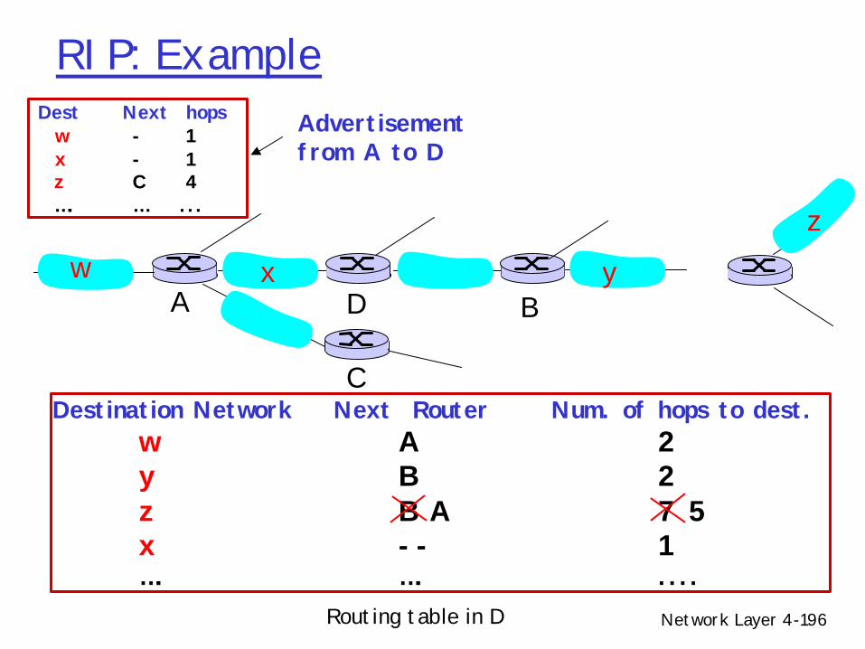
RIP: Example
Destination Network Next Router Num. of hops to dest.w A 2y B 2z B 7x -- 1…. …. ....
w x y
z
A
C
D B
Routing table in D
Network Layer 4-196
RIP: Example
Destination Network Next Router Num. of hops to dest.w A 2y B 2z B A 7 5x -- 1…. …. ....
Routing table in D
w x y
z
A
C
D B
Dest Next hopsw - 1x - 1z C 4…. … ...
Advertisementfrom A to D
Network Layer 4-197
RIP: Link Failure and RecoveryIf no advertisement heard after 180 sec -->
neighbor/link declared deadm routes via neighbor invalidatedm new advertisements sent to neighborsm neighbors in turn send out new advertisements (if
tables changed)m link failure info quickly propagates to entire netm poison reverse used to prevent ping-pong loops
(infinite distance = 16 hops)
Network Layer 4-198
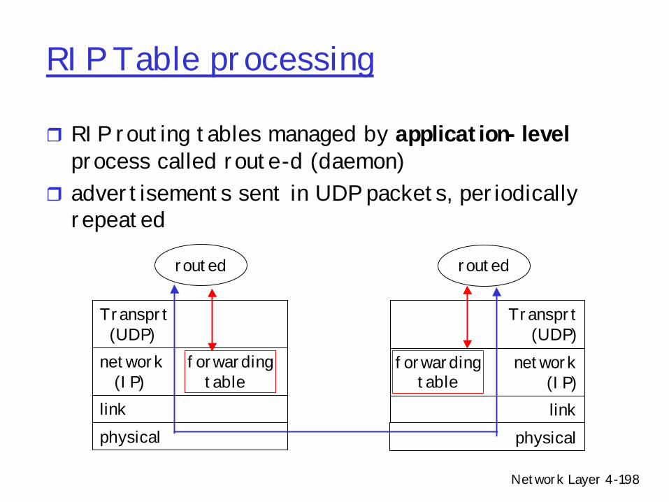
RIP Table processing
r RIP routing tables managed by application-levelprocess called route-d (daemon)
r advertisements sent in UDP packets, periodically repeated
physicallink
network forwarding(IP) table
Transprt(UDP)
routed
physicallink
network(IP)
Transprt(UDP)
routed
forwardingtable
Network Layer 4-199
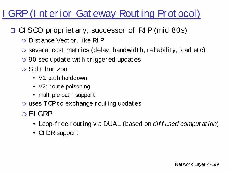
IGRP (Interior Gateway Routing Protocol)r CISCO proprietary; successor of RIP (mid 80s)
m Distance Vector, like RIPm several cost metrics (delay, bandwidth, reliability, load etc)m 90 sec update with triggered updatesm Split horizon
• V1: path holddown• V2: route poisoning• multiple path support
m uses TCP to exchange routing updatesm EIGRP
• Loop-free routing via DUAL (based on diffused computation)• CIDR support
HistoryrMid-80s: EGP (Exterior Gateway Protocol)m Used in original ARPAnet m Reachability protocol (no shortest path)
• Single bit for reachability information m Topology restricted to a tree (no cycles allowed)
• ARPA-managed packet switches at top of treem Unacceptable once Internet grew to multiple
independent backbonesr Result: BGP development
Network Layer 4-209
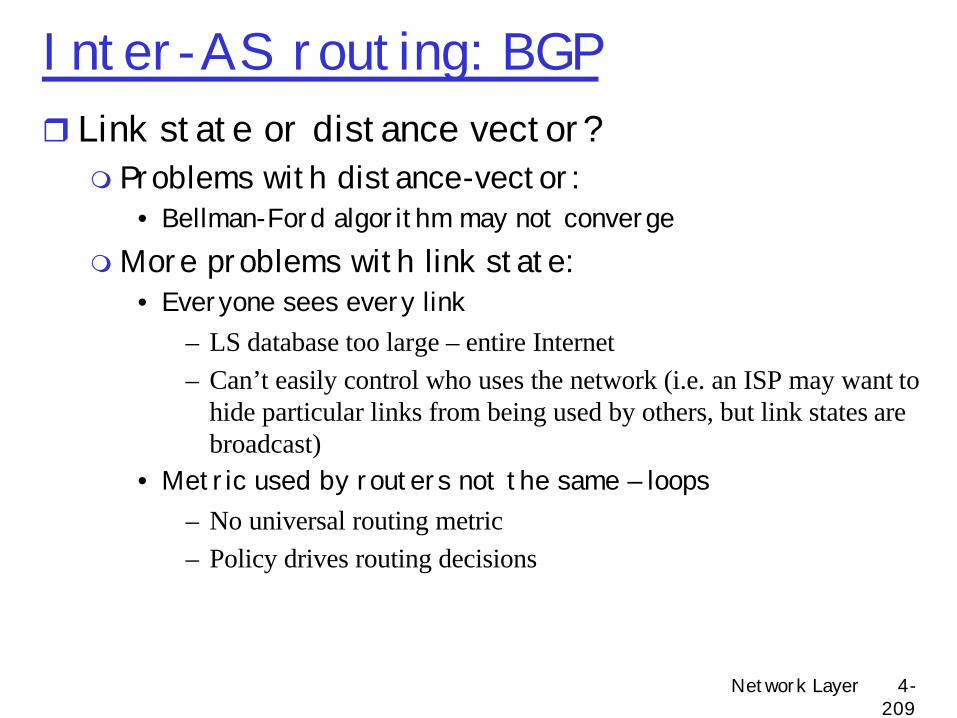
Inter-AS routing: BGPr Link state or distance vector?m Problems with distance-vector:
• Bellman-Ford algorithm may not convergemMore problems with link state:
• Everyone sees every link– LS database too large – entire Internet– Can’t easily control who uses the network (i.e. an ISP may want to
hide particular links from being used by others, but link states are broadcast)
• Metric used by routers not the same – loops– No universal routing metric– Policy drives routing decisions
Network Layer 4-210
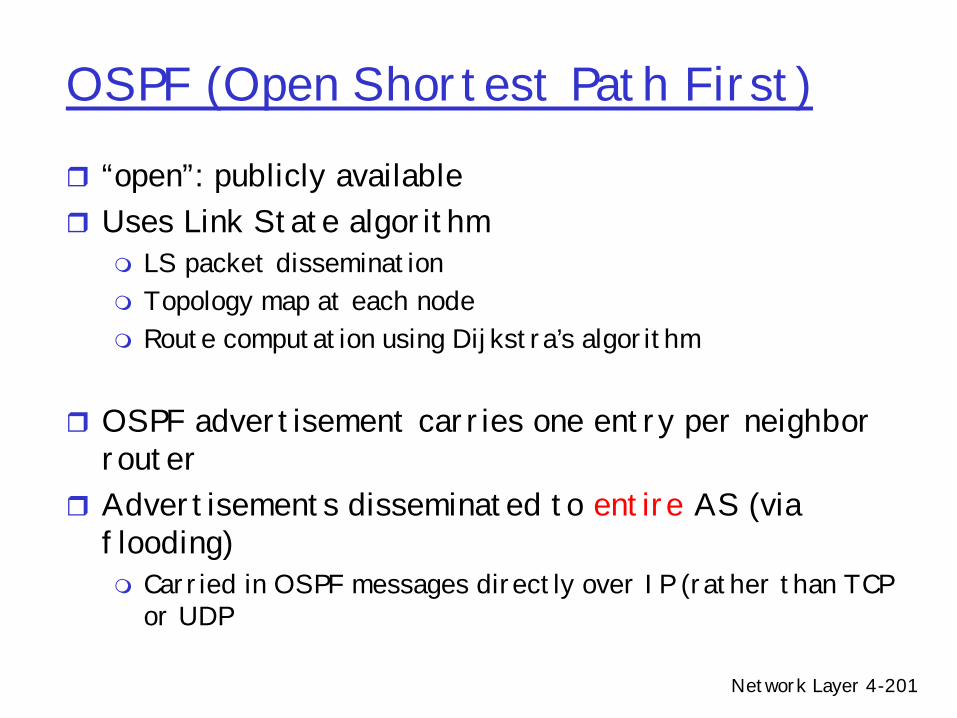
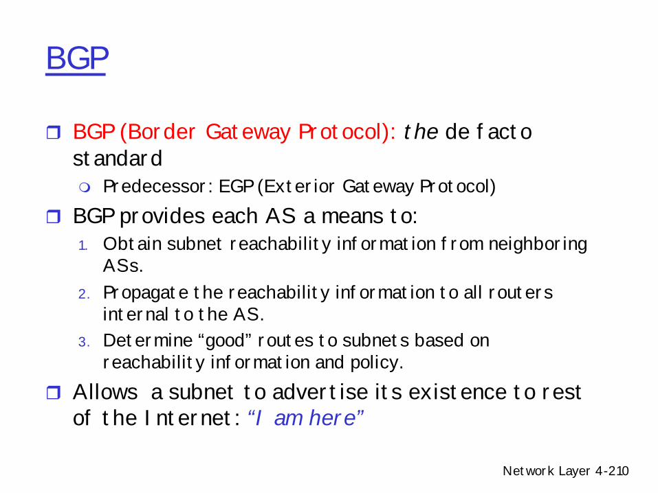
BGP
r BGP (Border Gateway Protocol): the de facto standardm Predecessor: EGP (Exterior Gateway Protocol)
r BGP provides each AS a means to:1. Obtain subnet reachability information from neighboring
ASs.2. Propagate the reachability information to all routers
internal to the AS.3. Determine “good” routes to subnets based on
reachability information and policy.r Allows a subnet to advertise its existence to rest
of the Internet: “I am here”
Network Layer 4-211
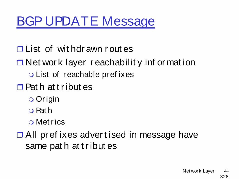
BGP messages
r BGP messages exchanged using TCP.m Advantages:
• Simplifies BGP• No need for periodic refresh - routes are valid until withdrawn,
or the connection is lost• Note recent news on BGP TCP spoofing attack• Incremental updates
m Disadvantages• Congestion control on a routing protocol?• Poor interaction during high load (Code Red)
m BGP messages:• OPEN: opens TCP connection to peer and authenticates sender• UPDATE: advertises new path (or withdraws old)• KEEPALIVE keeps connection alive in absence of UPDATES; also
ACKs OPEN request• NOTIFICATION: reports errors in previous msg; also used to
close connection
Network Layer 4-212
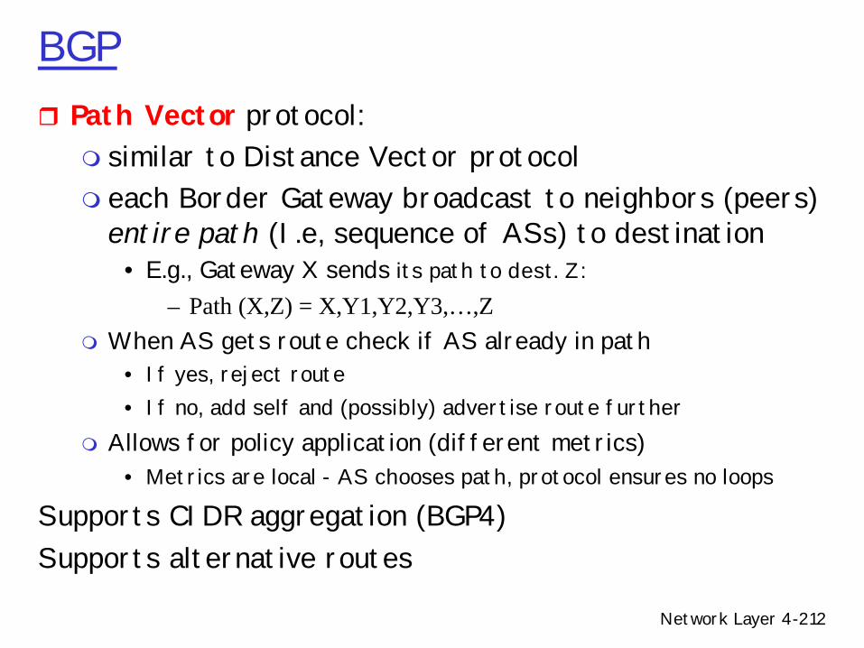
BGPr Path Vector protocol:m similar to Distance Vector protocolm each Border Gateway broadcast to neighbors (peers)
entire path (I.e, sequence of ASs) to destination• E.g., Gateway X sends its path to dest. Z:
– Path (X,Z) = X,Y1,Y2,Y3,…,Zm When AS gets route check if AS already in path
• If yes, reject route• If no, add self and (possibly) advertise route further
m Allows for policy application (different metrics) • Metrics are local - AS chooses path, protocol ensures no loops
Supports CIDR aggregation (BGP4)Supports alternative routes
Network Layer 4-213
BGP basicsr Pairs of routers (BGP peers) exchange routing info over semi-
permanent TCP conctns: BGP sessionsr Note that BGP sessions do not correspond to physical links.r When AS2 advertises a prefix to AS1, AS2 is promising it will
forward any datagrams destined to that prefix towards the prefix.m AS2 can aggregate prefixes in its advertisement
3b
1d
3a
1c2aAS3
AS1
AS21a
2c
2b
1b
3c
eBGP session
iBGP session
Network Layer 4-214
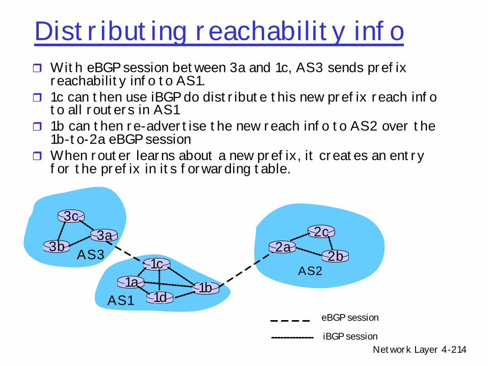
Distributing reachability infor With eBGP session between 3a and 1c, AS3 sends prefix
reachability info to AS1.r 1c can then use iBGP do distribute this new prefix reach info
to all routers in AS1r 1b can then re-advertise the new reach info to AS2 over the
1b-to-2a eBGP sessionr When router learns about a new prefix, it creates an entry
for the prefix in its forwarding table.
3b
1d
3a
1c2aAS3
AS1
AS21a
2c
2b
1b
3c
eBGP session
iBGP session
Network Layer 4-215
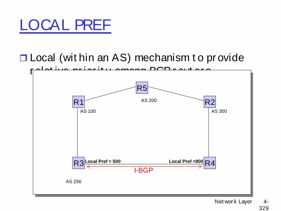
Policy with BGPr BGP provides capability for enforcing various
policiesr Policies are not part of BGP: they are provided
to BGP as configuration informationr BGP enforces policies by choosing paths from
multiple alternatives and controlling advertisement to other AS’s
• Preference for AS• Presence or absence of certain AS
m Path originm Link dynamicsm Early-exit
• Hot-potato routing for transit packets
Network Layer 4-217
Examples of BGP PoliciesrA multi-homed AS refuses to act as transitm Limit path advertisement
rA multi-homed AS can become transit for some AS’smOnly advertise paths to some AS’s
rAn AS can favor or disfavor certain AS’s for traffic transit from itself
Network Layer 4-218
BGP routing policy
Figure 4.5-BGPnew: a simple BGP scenario
A
B
C
W X
Y
legend:
customer network:
provider network
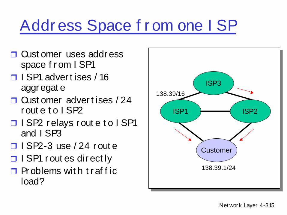
r A,B,C are provider networksr X,W,Y are customers (of provider networks)r X is dual-homed: attached to two networksm X does not want to route from B via X to Cm .. so X will not advertise to B a route to C
Network Layer 4-219
BGP routing policy (2)
Figure 4.5-BGPnew: a simple BGP scenario
A
B
C
W X
Y
legend:
customer network:
provider network
r A advertises to B the path AW r B advertises to X the path BAW r Should B advertise to C the path BAW?
m No way! B gets no “revenue” for routing CBAW since neither W nor C are B’s customers
m B wants to force C to route to w via Am B wants to route only to/from its customers!
Network Layer 4-220
Extra slides
Network Layer 4-221
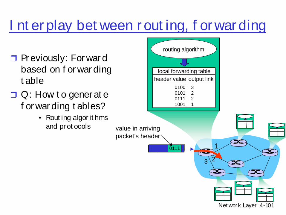
1
23
0111
value in arrivingpacket’s header
routing algorithm
local forwarding tableheader value output link
0100010101111001
3221
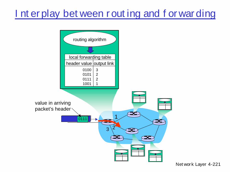
Interplay between routing and forwarding
Network Layer 4-222
Dijkstra’s algorithm: example
Step012345
N'u
uxuxy
uxyvuxyvw
uxyvwz
D(v),p(v)2,u2,u2,u
D(w),p(w)5,u4,x3,y3,y
D(x),p(x)1,u
D(y),p(y)8
2,x
D(z),p(z)8 8
4,y4,y4,y
u
yx
wv
z2
21
3
1
1
2
53
5
Network Layer 4-223
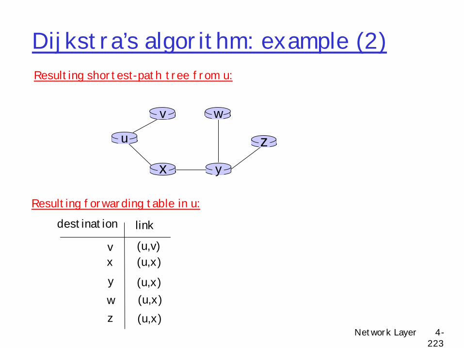
Dijkstra’s algorithm: example (2)
u
yx
wv
z
Resulting shortest-path tree from u:
vxywz
(u,v)(u,x)
(u,x)(u,x)(u,x)
destination link
Resulting forwarding table in u:
Network Layer 4-224
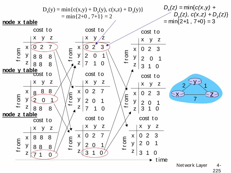
Distance Vector Algorithm
rDx(y) = estimate of least cost from x to yrDistance vector: Dx = [Dx(y): y ? N ]rNode x knows cost to each neighbor v:
c(x,v)rNode x maintains Dx = [Dx(y): y ? N ]rNode x also maintains its neighbors’
distance vectorsm For each neighbor v, x maintains
Prefix Match Link Interface11001000 00010111 00010 0 11001000 00010111 00011000 111001000 00010111 00011 2
otherwise 3
DA: 11001000 00010111 00011000 10101010
Examples
DA: 11001000 00010111 00010110 10100001 Which interface?
Which interface?
Network Layer 4-230
RIP Table example (continued)
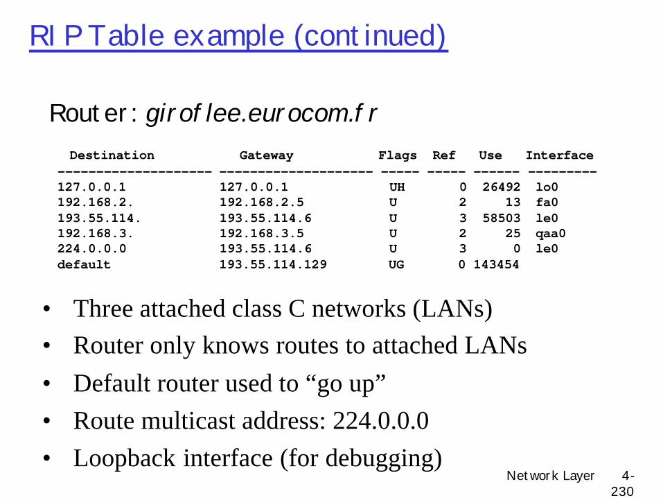
Router: giroflee.eurocom.fr
• Three attached class C networks (LANs)• Router only knows routes to attached LANs• Default router used to “go up”• Route multicast address: 224.0.0.0• Loopback interface (for debugging)
Destination Gateway Flags Ref Use Interface -------------------- -------------------- ----- ----- ------ ---------127.0.0.1 127.0.0.1 UH 0 26492 lo0 192.168.2. 192.168.2.5 U 2 13 fa0 193.55.114. 193.55.114.6 U 3 58503 le0 192.168.3. 192.168.3.5 U 2 25 qaa0 224.0.0.0 193.55.114.6 U 3 0 le0 default 193.55.114.129 UG 0 143454
Network Layer 4-231
Hierarchical routing
rUnused slides
Network Layer 4-232
BGP route selection
r Router may learn about more than 1 route to some prefix. Router must select route.
r Elimination rules:1. Local preference value attribute: policy
r 4.5 Routing algorithmsm Link statem Distance Vectorm Hierarchical routing
r 4.6 Routing in the Internetm RIPm OSPFm BGP
r 4.7 Broadcast and multicast routing
Network Layer 4-239
Router Architecture OverviewTwo key router functions:r RoutingmDetermine route taken by packets from source to
destinationmRun protocol (RIP, OSPF, BGP)
• Generate forwarding table from routing algorithms• Algorithms based on either (LS,DV)
r Forwardingm Process of moving packets from input port to output portmLookup forwarding table given information in packetmSwitch/forward datagrams from incoming to outgoing link
based on route
Network Layer 4-240
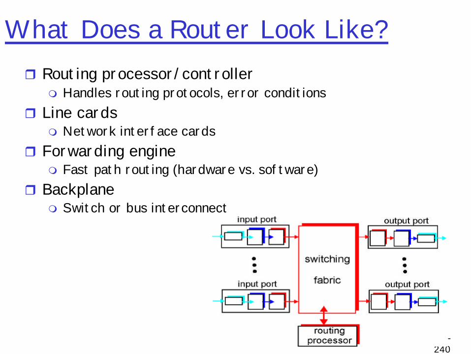
What Does a Router Look Like?r Routing processor/controller
m Handles routing protocols, error conditions r Line cards
m Network interface cardsr Forwarding engine
m Fast path routing (hardware vs. software)r Backplane
m Switch or bus interconnect
Network Layer 4-241
Typical mode of operationr Packet arrives arrives at inbound line cardr Header transferred to forwarding enginer Forwarding engine determines output interface given a
table initialized by routing processorr Forwarding engine signals result to line cardr Packet copied to outbound line card
Network Layer 4-242
Routing Processorr Runs routing protocol r Uploads forwarding table to forwarding engines
m Forwarding engines with two forwarding tables to allow easy switchover (double buffering)
r Typically performs “slow-path” processingm ICMP error messagesm IP option processingm IP fragmentation m IP multicast packets
Network Layer 4-243
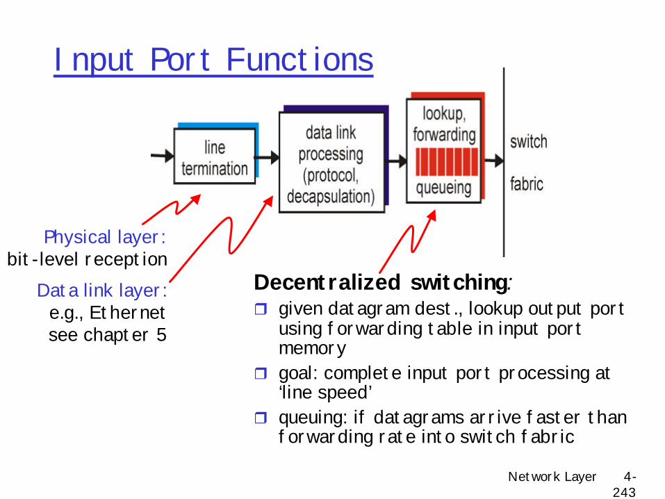
Input Port Functions
Decentralized switching:r given datagram dest., lookup output port
using forwarding table in input port memory
r goal: complete input port processing at ‘line speed’
r queuing: if datagrams arrive faster than forwarding rate into switch fabric
Physical layer:bit-level reception
Data link layer:e.g., Ethernetsee chapter 5
Network Layer 4-244
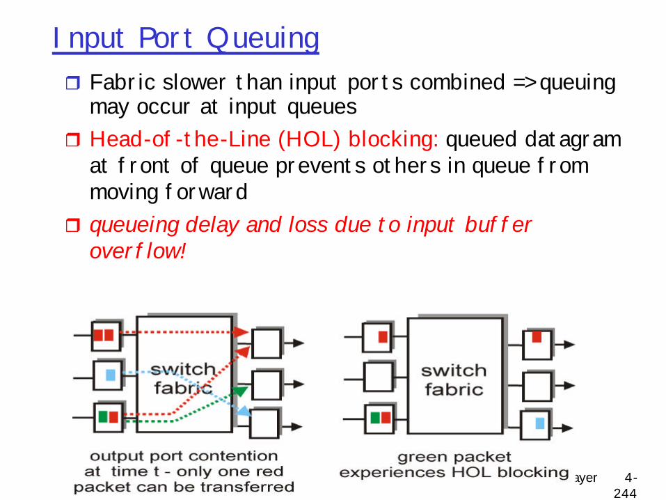
Input Port Queuingr Fabric slower than input ports combined => queuing
may occur at input queues r Head-of-the-Line (HOL) blocking: queued datagram
at front of queue prevents others in queue from moving forward
r queueing delay and loss due to input buffer overflow!
Network Layer 4-245
Input Port Queuingr Possible solutionm Virtual output buffering
• Maintain per output buffer at input• Solves head of line blocking problem• Each of MxN input buffer places bid for output
Network Layer 4-246
Forwarding Enginer Two major components
m Lookup logic/software• Data structures and algorithms to lookup route table• See previous section on IP route lookup
m Caches• Small, fast memory storing recent lookups
m Alternatives• Hardware-support• Hints
Network Layer 4-247
Cachesr Leverage temporal localityr Many packets to same destination
m Long flows help, short flows do not
r Similar to idea behind IP switching (ATM/MPLS) where long-lived flows map into single label
r Examplem Partridge, et. al. “A 50-Gb/s IP Router”, IEEE Trans. On Networking, Vol
6, No 3, June 1998. m 8KB L1 Icache
• Holds full forwarding codem 96KB L2 cache
• Forwarding table cachem 16MB L3 cache
• Full forwarding table x 2 - double buffered for updates
Network Layer 4-248
Alternativesr Lookup via content addressable memory (CAM)
m Hardware based route lookupm Input = tag, output = value associated with tagm Requires exact match with tag
• Multiple cycles (1 per prefix length searched) with single CAM• Multiple CAMs (1 per prefix) searched in parallel
m Ternary CAM• 0,1,don’t care values in tag match• Priority (i.e. longest prefix) by order of entries in CAM
r “Spatial caching” via protocol accelerationm Add clue (5 bits) to IP headerm Indicate where IP lookup ended on previous node (Bremler-Barr
SIGCOMM 99)
Network Layer 4-249
Types of network switching fabrics
Memory
BusMultistage interconnection
Crossbar interconnection
Network Layer 4-250
Types of network switching fabricsr Issuesm Switch contention
• Packets arrive faster than switching fabric can switch• Speed of switching fabric versus line card speed
determines input queuing vs. output queuing
Network Layer 4-251
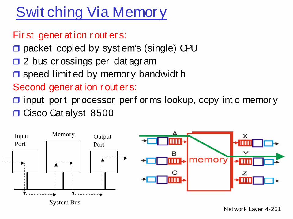
Switching Via MemoryFirst generation routers:r packet copied by system’s (single) CPUr 2 bus crossings per datagramr speed limited by memory bandwidth Second generation routers:r input port processor performs lookup, copy into memoryr Cisco Catalyst 8500
InputPort
OutputPort
Memory
System Bus
Network Layer 4-252
Switching Via Busr Datagram from input port memory directly to output port memory
via a shared busr Issues
m Bus contention: switching speed limited by bus bandwidthr Examples
m 1 Gbps bus, Cisco 1900: sufficient speed for access and enterprise routers (not regional or backbone)
Network Layer 4-253
Switching Via An Interconnection Networkr Overcome bus bandwidth limitationsr Crossbar networks
m Fully connected (n2 elements)m All one-to-one, invertible permutations supported
r Issuesm Crossbar with N2 elements hard to scale
Network Layer 4-254
Switching Via An Interconnection Network
r Multi-stage interconnection networks (Banyan)m Initially developed to connect processors in multiprocessorm Typically O(n log n) elementsm Datagram fragmented fixed length cells, switched through the
fabricr Issues
m Blocking (not all one-to-one, invertible permutations supported)
r Examplem Cisco 12000: Gbps through an interconnection network
A
B
C
D
W
X
Y
Z
Network Layer 4-255
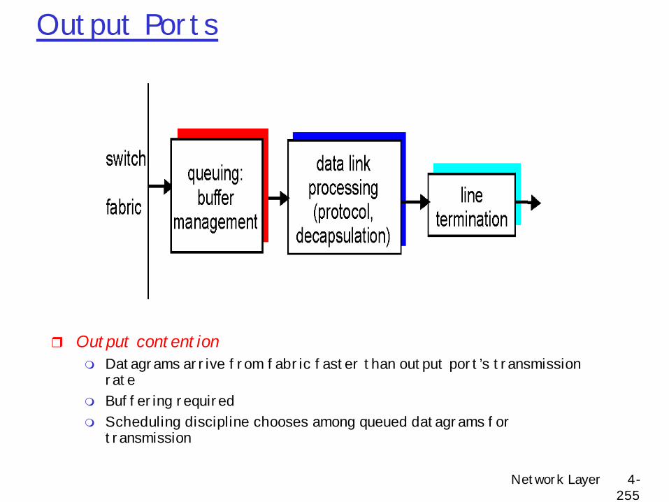
Output Ports
r Output contentionm Datagrams arrive from fabric faster than output port’s transmission
ratem Buffering requiredm Scheduling discipline chooses among queued datagrams for
transmission
Network Layer 4-256
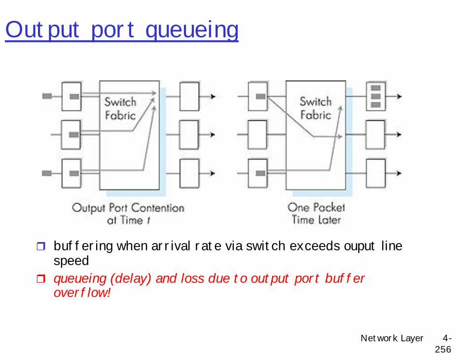
Output port queueing
r buffering when arrival rate via switch exceeds ouput line speed
r queueing (delay) and loss due to output port buffer overflow!
r 4.5 Routing algorithmsm Link statem Distance Vectorm Hierarchical routing
r 4.6 Routing in the Internetm RIPm OSPFm BGP
r 4.7 Broadcast and multicast routing
Network Layer 4-258
R1
R2
R3 R4
sourceduplication
R1
R2
R3 R4
in-networkduplication
duplicatecreation/transmissionduplicate
duplicate
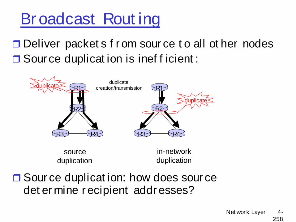
Broadcast RoutingrDeliver packets from source to all other nodesrSource duplication is inefficient:
rSource duplication: how does source determine recipient addresses?
Network Layer 4-259
In-network duplication
r Flooding: when node receives brdcst pckt, sends copy to all neighborsm Problems: cycles & broadcast storm
r Controlled flooding: node only brdcsts pktif it hasn’t brdcst same packet beforemNode keeps track of pckt ids already brdcstedmOr reverse path forwarding (RPF): only forward
pckt if it arrived on shortest path between node and source
rSpanning treemNo redundant packets received by any node
Network Layer 4-260
A
B
G
DE
c
F
A
B
G
DE
c
F
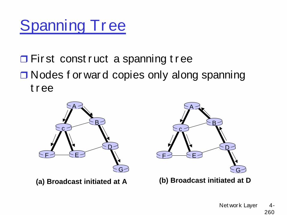
(a) Broadcast initiated at A (b) Broadcast initiated at D
Spanning Tree
r First construct a spanning treerNodes forward copies only along spanning
tree
Network Layer 4-261
A
B
G
DE
c
F1
2
3
4
5
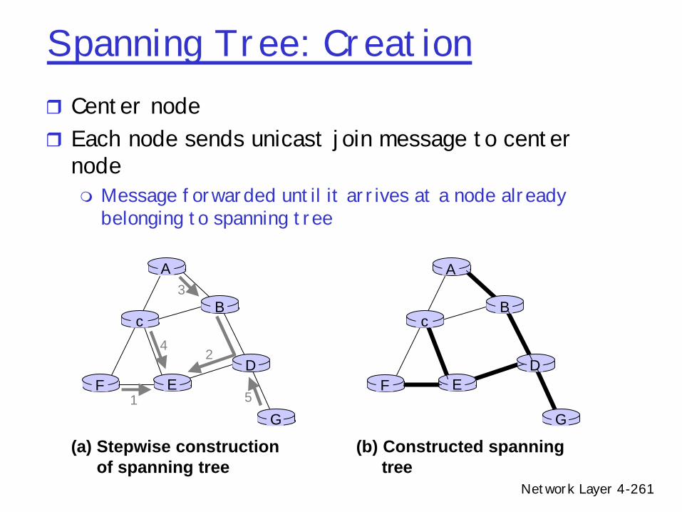
(a) Stepwise construction of spanning tree
A
B
G
DE
c
F
(b) Constructed spanning tree
Spanning Tree: Creationr Center noder Each node sends unicast join message to center
nodem Message forwarded until it arrives at a node already
belonging to spanning tree
Multicast Routing: Problem StatementrGoal: find a tree (or trees) connecting
routers having local mcast group members m tree: not all paths between routers usedm source-based: different tree from each sender to rcvrsm shared-tree: same tree used by all group members
Shared tree Source-based trees
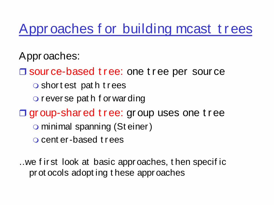
Approaches for building mcast trees
Approaches:r source-based tree: one tree per sourcem shortest path treesm reverse path forwarding
r group-shared tree: group uses one treemminimal spanning (Steiner) m center-based trees
…we first look at basic approaches, then specific protocols adopting these approaches
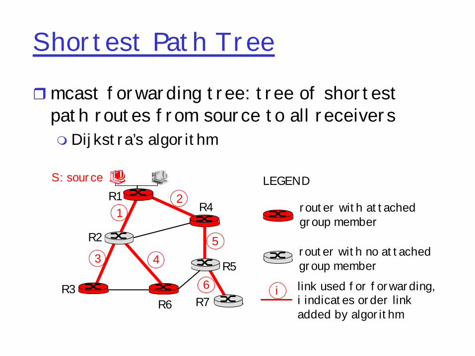
Shortest Path Tree
rmcast forwarding tree: tree of shortest path routes from source to all receiversm Dijkstra’s algorithm
R1
R2
R3
R4
R5
R6 R7
21
6
3 45
i
router with attachedgroup member
router with no attachedgroup memberlink used for forwarding,i indicates order linkadded by algorithm
LEGENDS: source
Reverse Path Forwarding
if (mcast datagram received on incoming link on shortest path back to center)then flood datagram onto all outgoing linkselse ignore datagram
q rely on router’s knowledge of unicast shortest path from it to sender
q each router has simple forwarding behavior:
Reverse Path Forwarding: example
• result is a source-specific reverse SPT– may be a bad choice with asymmetric links
R1
R2
R3
R4
R5
R6 R7
router with attachedgroup member
router with no attachedgroup memberdatagram will be forwarded
LEGENDS: source
datagram will not be forwarded
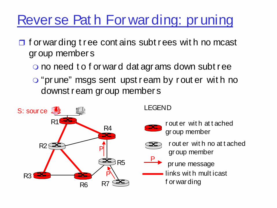
Reverse Path Forwarding: pruningr forwarding tree contains subtrees with no mcast
group membersm no need to forward datagrams down subtreem “prune” msgs sent upstream by router with no
downstream group members
R1
R2
R3
R4
R5
R6 R7
router with attachedgroup memberrouter with no attachedgroup memberprune message
LEGENDS: source
links with multicastforwarding
P
P
P
Shared-Tree: Steiner Tree
rSteiner Tree: minimum cost tree connecting all routers with attached group members
r problem is NP-completer excellent heuristics existsr not used in practice:m computational complexitym information about entire network neededmmonolithic: rerun whenever a router needs to
join/leave
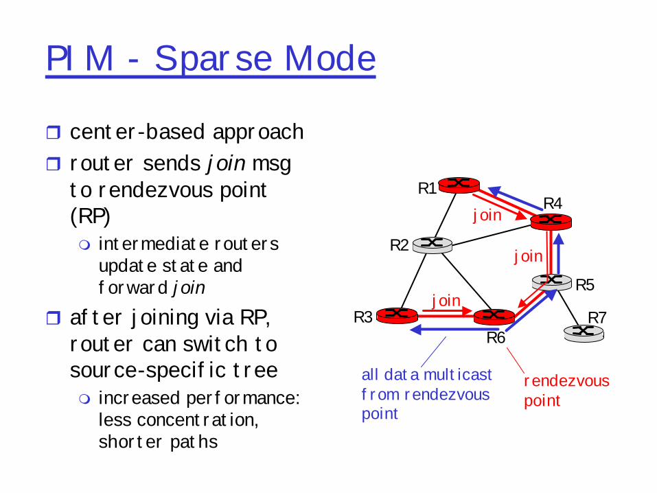
Center-based trees
r single delivery tree shared by allr one router identified as “center” of treer to join:m edge router sends unicast join-msg addressed
to center routerm join-msg “processed” by intermediate routers
and forwarded towards centerm join-msg either hits existing tree branch for
this center, or arrives at centerm path taken by join-msg becomes new branch of
tree for this router
Center-based trees: an example
Suppose R6 chosen as center:
R1
R2
R3
R4
R5
R6 R7
router with attachedgroup memberrouter with no attachedgroup memberpath order in which join messages generated
NL: Routing Update SynchronizationrDynamic robustness issue to consider...
m Intuitive assumption that independent streams will not synchronize is not always valid
m Abrupt transition from unsynchronized to synchronized system states
Network Layer 4-281
NL: How Synchronization OccursT
AMessage from B
Weak Coupling when A’s behavior is triggered off of B’smessage arrival!
A
T
Weak couplingcan result in
eventual synchronization
Network Layer 4-282
NL: Examples/Sources of Synchronizationr TCP congestion window behaviorr Periodic transmission by audio/video applicationsr Synchronized client restartr Routing
m Periodic routing protocol messages from different routersm Lots of this in initial routing protocols....
Network Layer 4-283
NL: Routing Source of Synchronizationr Router resets timer after processing its own and incoming
updatesr Creates weak coupling among routersr Solutions
m Set timer based on clock event that is not a function of processing other routers’ updates, or
m Add randomization, or reset timer before processing update• With increasing randomization, abrupt transition from
predominantly synchronized to predominantly unsynchronized• Most protocols now incorporate some form of randomization
Network Layer 4-284
NL: Routing Instabilityr References
m C. Labovitz, R. Malan, F. Jahanian, ``Internet Routing Stability'', SIGCOMM 1997.
r Record of BGP messages at major exchangesr Discovered orders of magnitude larger than expected
updatesm Bulk were duplicate withdrawals
• Stateless implementation of BGP – did not keep track of information passed to peers
• Impact of few implementationsm Strong frequency (30/60 sec) components
• Interaction with other local routing/links etc.
Network Layer 4-285
NL: Route Flap StormrOverloaded routers fail to send Keep_Alive
message and marked as downr BGP peers find alternate pathsrOverloaded router re-establishes peering
sessionrMust send large updates r Increased load causes more routers to fail!
Network Layer 4-286
NL: Route Flap Dampeningr Routers now give higher priority to
BGP/Keep_Alive to avoid problemrAssociate a penalty with each route on changem Increase when route flapsm Exponentially decay penalty with time
rWhen penalty reaches threshold, suppress route
Network Layer 4-287
NL: Overlay Routingr Basic idea:
m Treat multiple hops through IP network as one hop in an overlay network
m Run routing protocol on overlay nodes
rWhy?m For performance – can run more clever protocol on overlaym For efficiency – can make core routers very simplem For functionality – can provide new features such as multicast,
active processing, IPv6
Network Layer 4-288
NL: Overlay for Performancer References
m Savage et. al. “The End-to-End Effects of Internet Path Selection”, SIGCOMM 99
m Anderson et. al. “Resilient Overlay Networks”, SOSP 2001r Why would IP routing not give good performance?
m Policy routing – limits selection/advertisement of routesm Early exit/hot-potato routing – local not global incentivesm Lack of performance based metrics – AS hop count is the wide
area metricr How bad is it really?
m Look at performance gain an overlay provides
Network Layer 4-289
NL: Quantifying Performance LossrMeasure round trip time (RTT) and loss rate
between pairs of hostsm ICMP rate limiting
rAlternate path characteristicsm 30-55% of hosts had lower latencym 10% of alternate routes have 50% lower latencym 75-85% have lower loss rates
Network Layer 4-290
NL: Bandwidth Estimationr RTT & loss for multi-hop pathm RTT by additionm Loss either worst or combine of hops – why?
• Large number of flowsà combination of probabilities• Small number of flowsà worst hop
r Bandwidth calculationm TCP bandwidth is based primarily on loss and RTT
r 70-80% paths have better bandwidthr 10-20% of paths have 3x improvement
Network Layer 4-291
NL: Overlay for EfficiencyrMulti-path routingmMore efficient use of links or QOSmNeed to be able to direct packets based on more
than just destination address à can be computationally expensive
mWhat granularity? Per source? Per connection? Per packet?
• Per packet à re-ordering• Per source, per flow à coarse grain vs. fine grain
m Take advantage of relative duration of flows• Most bytes on long flows
Network Layer 4-292
NL: Overlay for FeaturesrHow do we add new features to the network?m Does every router need to support new feature?m Choices
• Reprogram all routers à active networks• Support new feature within an overlay
m Basic technique: tunnel packets rTunnelsm IP-in-IP encapsulationm Poor interaction with firewalls, multi-path routers,
etc.
Network Layer 4-293
NL: Examplesr IP V6 & IP Multicastm Tunnels between routers supporting feature
rMobile IPmHome agent tunnels packets to mobile host’s
NL: Overlay ChallengesrHow do you build efficient overlaym Probably don’t want all N2 links – which links to
create?mWithout direct knowledge of underlying topology
how to know what’s nearby and what is efficient?
Network Layer 4-295
NL: Future of OverlayrApplication specific overlaysmWhy should overlay nodes only do routing?
r Cachingm Intercept requests and create responses
rTranscodingm Changing content of packets to match available
bandwidthr Peer-to-peer applications
Network Layer 4-296
NL: Routing alternatives: Landmark routingr Details about things nearby and less information about
things far awayr Not defined by arbitrary boundaries
m Thus, not well suited to the real world that does have administrative boundaries
r Example: My apartment• MtHood.Portland.USBancorpTower.PearlDistrict.KearneyPlaza• From Beaverton
– Go towards Mt. Hood– See USBancorpTower before running into Mt.Hood – See PearlDistrict before running into USBancorpTower– Reach PearlDistrict and route to Kearney Plaza 2 blocks away
• From The Dalles– Go towards Mt. Hood, reach it– Go towards Portland, see USBancorpTower– Go towards and reach USBancorpTower– Go towards and reach PearlDistrict, route to Kearney Plaza 2 blocks away
Network Layer 4-297
NL: A Landmark
1
2
3
4
56
7
89
10
11
Router 1 is a landmarkof radius 2
Network Layer 4-298
NL: Landmark Overviewr Landmark routers have “height” which determines how
far away they can be seen (visibility)m Routers within radius n can see a landmark router LMn
• See = routers have LMn’s address and know next hop to reach it.
m Router x as an entry for router y if x is within radius of ym Routing table: Landmark (LM2(d)), Level(2), Next hop
r Intuitionm Everyone knows how to get to the highest landmark (level N)m Highest landmark knows how to get you to any landmark at level N-1
(i.e. the N-1 level landmark that matches your destination)m That level N-1 landmark, knows how to get you to your level N-2, etc.m Along the way, you may find a router that lets you short-circuit path
to higher landmarks and take you to destination
Network Layer 4-299
NL: LM Hierarchy Definitionr Each LM i associated with level (i) and radius (ri)r Every node is an LM0 landmarkr Recursion: some LMi are also LMi+1m Every LMi sees at least one LMi+1
rTerminating state when all level j LMs are seen by entire network
Network Layer 4-300
NL: LM Self-configuration
r Bottom-up hierarchy construction algorithmm Every router is L0 landmarkm All Li landmarks run election to self-promote one or more Li+1
landmarksr LM level maps to radius (part of configuration), e.g.:
rSymmetric routingmWhile preference symmetric paths, many are
asymmetricr Packet re-orderingmMay trigger TCP’s fast retransmit algorithm
rOther concerns:m Addressing, DNS, aggregation
Network Layer 4-308
Multi-homing to a Single Provider
ISP
Customer
R1
R2
r Easy solution:m Use IMUX or Multi-link
PPPr Hard solution:
m Use BGPm Makes assumptions
about traffic (same amount of prefixes can be reached from both links)
Network Layer 4-309
Multi-homing to a Single Provider
ISP
Customer
R1
R2
r If multiple prefixes, may use MEDm Good if traffic load to
prefixes is equalr If single prefix, load
may be unequalm Break-down prefix and
advertise different prefixes over different links
R3
138.39/16 204.70/16
Network Layer 4-310
Multi-homing to a Single Provider
ISP
Customer
R1 R2
r For traffic to customer, same as before:m Use MEDm Good if traffic load to
prefixes is equalr For traffic to ISP:
m R3 alternates linksm Multiple default routes
R3
138.39/16 204.70/16
Network Layer 4-311
Multi-homing to a Single Provider
ISP
Customer
R1 R2
r Most reliable approachm No equipment sharing
r Use MED
R3
138.39/16 204.70/16
R4
Network Layer 4-312
Outline
r External BGP (E-BGP)
r Internal BGP (I-BGP)
rMulti-Homing
rStability Issues
Network Layer 4-313
Multi-homing
rWith multi-homing, a single network has more than one connection to the Internet.
r Improves reliability and performance:m Can accommodate link failurem Bandwidth is sum of links to Internet
r Challengesm Getting policy right (MED, etc..)m Addressing
Network Layer 4-314
Multi-homing to Multiple Providers
r Major issues:m Addressingm Aggregation
r Customer address space:m Delegated by ISP1m Delegated by ISP2m Delegated by ISP1 and
ISP2m Obtained independently
ISP1 ISP2
ISP3
Customer
Network Layer 4-315
Address Space from one ISPr Customer uses address
space from ISP1r ISP1 advertises /16
aggregater Customer advertises /24
route to ISP2r ISP2 relays route to ISP1
and ISP3r ISP2-3 use /24 router ISP1 routes directlyr Problems with traffic
load?
138.39/16
138.39.1/24
ISP1 ISP2
ISP3
Customer
Network Layer 4-316
Pitfalls
r ISP1 aggregates to a /19 at border router to reduce internal tables.
r ISP1 still announces /16.r ISP1 hears /24 from
ISP2.r ISP1 routes packets for
customer to ISP2!r Workaround: ISP1 must
inject /24 into I-BGP.
138.39.0/19
138.39/16
ISP1 ISP2
ISP3
Customer
138.39.1/24
Network Layer 4-317
Address Space from Both ISPs
r ISP1 and ISP2 continue to announce aggregates
r Load sharing depends on traffic to two prefixes
r Lack of reliability: if ISP1 link goes down, part of customer becomes inaccessible.
r Customer may announce prefixes to both ISPs, but still problems with longest match as in case 1.
138.39.1/24 204.70.1/24
ISP1 ISP2
ISP3
Customer
Network Layer 4-318
Address Space Obtained Independentlyr Offers the most
control, but at the cost of aggregation.
r Still need to control paths
ISP1 ISP2
ISP3
Customer
Network Layer 4-319
Measurement of Real Ethernet
r Evaluate performance in some typical scenariosm Scenario 1
• Topology: 4 clusters of 6 hosts – similar to office configuration
• Fixed pkt size• Throughput decreases with number of hosts &
increases with pkt size – as expected• Fairness improves with number of hosts – capture
effects less likely• Only linear increase in delay with number of hosts -
unexpected
Network Layer 4-320
Measurement of Real Ethernet
rScenario 2Topology: 23 hosts on short netLoad: fixed pkt sizeImprovement in bit rate over scenario 1Scenario 3Topology: 4 clustersLoad: bimodal pkt size7/1 ratio of small to large pkts is sufficient to greatly improve total bit rate
Network Layer 4-321
How to Improve Performance
r No long cablesr Fewer hosts per cabler Use large packetsr Don't mix real-time w/ bulk-data if possibler Can’t provide good efficiency/throughput and
good latencyr Ethernet Packet Traces
m Ethernet traffic is “self-similar” (fractal)m Bursty at every time scale (msecs to months)m Implication?
• On average, low load• Occasional peaks
Network Layer 4-322
***MISC_IP_ROUTING***
Network Layer 4-323
Problems
r Routing table sizemNeed an entry for all paths to all networks
r Required memory= O((N + M*A) * K)mN: number of networksmM: mean AS distance (in terms of hops)m A: number of AS’sm K: number of BGP peers
Network Layer 4-324
Routing Table Size
Mean AS Distance Number of AS’s
2,100 5 59
4,000 10 100
10,000 15 300
BGP Peers/Net
3
6
10
100,000 20 3,000 20
Networks Memory
27,000
108,000
490,000
1,040,000
r Problem reduced with CIDR
Network Layer 4-325
Routing Information Bases (RIB)r Routes are stored in RIBsrAdj-RIBs-In: routing info that has been
learned from other routers (unprocessed routing info)
r Loc-RIB: local routing information selected from Adj-RIBs-In (routes selected locally)
rAdj-RIBs-Out: info to be advertised to peers (routes to be advertised)
Network Layer 4-326
BGP Common Header
Length (2 bytes) Type (1 byte)
0 1 2 3
Marker (security and message delineation)16 bytes
Types: OPEN, UPDATE, NOTIFICATION, KEEPALIVE
Network Layer 4-327
BGP Messages
r Openm Announces AS IDm Determines hold timer – interval between keep_alive or
update messages, zero interval implies no keep_aliver Keep_alive
• Sent periodically (but before hold timer expires) to peers to ensure connectivity.
• Sent in place of an UPDATE messager Notification
• Used for error notification• TCP connection is closed immediately after notification
Network Layer 4-328
BGP UPDATE Message
r List of withdrawn routesrNetwork layer reachability informationm List of reachable prefixes
r Path attributesmOriginm PathmMetrics
rAll prefixes advertised in message have same path attributes
Network Layer 4-329
LOCAL PREF
r Local (within an AS) mechanism to provide relative priority among BGP routers
R1 R2
R3 R4I-BGP
AS 256
AS 300
Local Pref = 500 Local Pref =800
AS 100
R5AS 200
Network Layer 4-330
AS_PATH
r List of traversed AS’s
AS 500
AS 300
AS 200 AS 100
180.10.0.0/16 300 200 100170.10.0.0/16 300 200
170.10.0.0/16 180.10.0.0/16
Network Layer 4-331
CIDR and BGP
AS X197.8.2.0/24
AS Y197.8.3.0/24
AS T (provider)197.8.0.0/23
AS Z
What should T announce to Z?
Network Layer 4-332
Options
rAdvertise all paths:m Path 1: through T can reach 197.8.0.0/23m Path 2: through T can reach 197.8.2.0/24m Path 3: through T can reach 197.8.3.0/24
r But this does not reduce routing tables! We would like to advertise:m Path 1: through T can reach 197.8.0.0/22
Network Layer 4-333
Sets and Sequences
r Problem: what do we list in the route?• List T: omitting information not acceptable, may lead
to loops• List T, X, Y: misleading, appears as 3-hop path
rSolution: restructure AS Path attribute as:• Path: (Sequence (T), Set (X, Y))• If Z wants to advertise path:
– Path: (Sequence (Z, T), Set (X, Y))• In practice used only if paths in set have same
attributes
Network Layer 4-334
Multi-Exit Discriminator (MED)
rHint to external neighbors about the preferred path into an AS mNon-transitive attribute (we will see later why)m Different AS choose different scales
rUsed when two AS’s connect to each other in more than one place
Network Layer 4-335
MED
rHint to R1 to use R3 over R4 linkr Cannot compare AS40’s values to AS30’s
R1 R2
R3 R4
AS 30
AS 40
180.10.0.0MED = 120
180.10.0.0MED = 200
AS 10
180.10.0.0MED = 50
Network Layer 4-336
MED• MED is typically used in provider/subscriber scenarios• It can lead to unfairness if used between ISP because it
may force one ISP to carry more traffic:
SF
NY
• ISP1 ignores MED from ISP2• ISP2 obeys MED from ISP1• ISP2 ends up carrying traffic most of the way
ISP1
ISP2
Network Layer 4-337
Other Attributes
rORIGINm Source of route (IGP, EGP, other)
rNEXT_HOPm Address of next hop router to usem Used to direct traffic to non-BGP router
r Check out http://www.cisco.com for full explanation
Network Layer 4-338
Decision Process
r Processing order of attributes:m Select route with highest LOCAL-PREFm Select route with shortest AS-PATHm Apply MED (if routes learned from same
neighbor)
Network Layer 4-339
Outline
r External BGP (E-BGP)
r Internal BGP (I-BGP)
rMulti-Homing
rStability Issues
Network Layer 4-340
Internal vs. External BGP
R3 R4R1
R2
E-BGP
•BGP can be used by R3 and R4 to learn routes•How do R1 and R2 learn routes?•Option 1: Inject routes in IGP
•Only works for small routing tables•Option 2: Use I-BGP
AS1 AS2
Network Layer 4-341
Internal BGP (I-BGP)
rSame messages as E-BGPrDifferent rules about re-advertising
prefixes:m Prefix learned from E-BGP can be advertised to
I-BGP neighbor and vice-versa, but m Prefix learned from one I-BGP neighbor cannot
be advertised to another I-BGP neighborm Reason: no AS PATH within the same AS and
thus danger of looping.
Network Layer 4-342
Internal BGP (I-BGP)
R3 R4R1
R2
E-BGP
I-BGP
• R3 can tell R1 and R2 prefixes from R4• R3 can tell R4 prefixes from R1 and R2• R3 cannot tell R2 prefixes from R1
R2 can only find these prefixes through a direct connection to R1Result: I-BGP routers must be fully connected (via TCP)!
• contrast with E-BGP sessions that map to physical links
AS1 AS2
Network Layer 4-343
Link Failures
rTwo types of link failures:m Failure on an E-BGP linkm Failure on an I-BGP Link
rThese failures are treated completely different in BGP
rWhy?
Network Layer 4-344
Failure on an E-BGP Link
AS1 R1 AS2R2Physical link
E-BGP session
138.39.1.1/30 138.39.1.2/30
• If the link R1-R2 goes down• The TCP connection breaks• BGP routes are removed
• This is the desired behavior
Network Layer 4-345
Failure on an I-BGP Link
R1
R2
R3
Physical link
I-BGP connection
138.39.1.1/30
138.39.1.2/30
•If link R1-R2 goes down, R1 and R2 should still be able to exchange traffic
•The indirect path through R3 must be used•Thus, E-BGP and I-BGP must use different conventions with respect to TCP endpoints
Network Layer 4-346
Distance Vector in Practice
r RIP and RIP2m Uses split-horizon/poison reverse
r BGPm Propagates entire pathm Path also used for effecting policies