71 CHAPTER 4 PID CONTROLLER TUNING USING PERFORMANCE INDEX MINIMIZATION 4.1 INTRODUCTION In the past four decades, numerous researchers dealt with the tuning of PID controllers. Increasing emphasis on the measurement of control system performance is found in the recent literature on automatic control. Modern control theory assumes that it is possible for the system designer to specify quantitatively the desired system performance. Then a performance index is calculated or measured and used to evaluate the system performance. A quantitative measure of a system performance is also essential for the operation of modern adaptive control systems, for automatic parameter optimisation of a control system and for the design of optimum systems (Dorf & Bishop 2002). The performance of the system is optimised by adjusting its parameters such that the performance index reaches an extreme value, commonly a minimum value. Various performance indices employed in control applications are Integral Absolute Error (IAE), Integral Time Absolute Error (ITAE), Integral Time Square Error (ITSE) and Mean Square Error (MSE). The performance indices which are defined based on the manipulation on the error signal e(t) are represented as follows:
Transcript
71
CHAPTER 4
PID CONTROLLER TUNING USING PERFORMANCE
INDEX MINIMIZATION
4.1 INTRODUCTION
In the past four decades, numerous researchers dealt with the
tuning of PID controllers.
Increasing emphasis on the measurement of control system
performance is found in the recent literature on automatic control. Modern
control theory assumes that it is possible for the system designer to specify
quantitatively the desired system performance. Then a performance index is
calculated or measured and used to evaluate the system performance. A
quantitative measure of a system performance is also essential for the
operation of modern adaptive control systems, for automatic parameter
optimisation of a control system and for the design of optimum systems (Dorf
& Bishop 2002). The performance of the system is optimised by adjusting its
parameters such that the performance index reaches an extreme value,
commonly a minimum value.
Various performance indices employed in control applications are
Integral Absolute Error (IAE), Integral Time Absolute Error (ITAE), Integral
Time Square Error (ITSE) and Mean Square Error (MSE). The performance
indices which are defined based on the manipulation on the error signal e(t)
are represented as follows:
72
dt|)t(e|IA
E
(4
.1)
dt|)t(e|tIT
AE
(4.2
)
dte
ISE
2
(4.3
)
dtte
ITSE
2
(4.4
)
Tdte
MSE
2
(4.5
)
ITA
E w
as u
sed
by C
ha &
Han
(199
9) fo
r PID
con
trolle
r tun
ing
by
para
met
er e
stim
atio
n. B
alam
urug
an e
t al (
2009
) sug
gest
ed th
at IS
E, IT
SE a
nd
ITA
E ar
e us
eful
for o
ptim
al P
ID g
ain
tuni
ng o
f hea
vy d
uty
gas t
urbi
ne p
lant
.
MSE
is e
mpl
oyed
as
the
optim
izat
ion
func
tion
for
PID
con
trolle
r
tuni
ng (
Dum
an e
t al 2
011;
Tho
mas
& P
oong
odi 2
009)
to o
btai
n th
e po
sitio
n
and
spee
d co
ntro
l of
DC
mot
or.
Nag
araj
& V
ijaya
kum
ar (
2011
), (2
012)
utili
zed
ISE
to tu
ne P
ID c
ontro
ller
and
achi
eve
the
desi
red
spee
d co
ntro
l of
DC
mot
or. M
alho
tra e
t al (
2010
), N
atsh
eh &
Bur
agga
(20
10)
prop
osed
IA
E
and
ITA
E as
per
form
ance
crit
eria
for
the
desi
gn o
f em
bedd
ed h
ybrid
fuz
zy-
GA
con
trols
trate
gy fo
r spe
ed c
ontro
l of D
C se
rvo
mot
or.
In B
LDC
mot
or c
ontro
l (C
heng
et
al 2
001;
Liu
& F
orsy
th 2
005;
Nas
ri et
al 2
007;
Nar
mad
ha &
Thy
agar
ajan
201
0; R
eddy
& K
alav
athi
201
1)
and
DC
m
otor
co
ntro
l (A
ltaye
f &
Q
un-x
iong
20
09;
Ana
ndar
aju
&
Putta
swam
y 20
12; G
irira
jkum
ar e
t al 2
010;
Nag
araj
et a
l 200
8; N
agar
aj e
t al
2010
; Nag
araj
& M
urug
anan
th 2
010)
app
licat
ions
, IA
E, IT
AE,
ISE,
ITSE
and
MSE
ar
e em
ploy
ed
as
perf
orm
ance
in
dice
s to
ac
hiev
e th
e op
timum
perf
orm
ance
usi
ng v
ario
us so
ft co
mpu
ting
and
hybr
id c
ontro
l tec
hniq
ues.
It ha
s be
en f
ound
tha
t PI
D c
ontro
ller
is t
uned
by
conv
entio
nal
tuni
ng a
lgor
ithm
s ba
sed
on t
he tr
ansf
er f
unct
ion
mod
el a
nd t
he c
lose
d lo
op
73
PID
con
trolle
d B
LDC
driv
e-ba
sed
posi
tion
cont
rol
syst
em s
uffe
rs f
rom
over
shoo
t pro
blem
s. Th
is o
vers
hoot
is n
ot to
lera
ble
in p
reci
se p
ositi
on c
ontro
l
appl
icat
ions
. BLD
C d
rive
syst
em e
xhib
its n
on-li
near
cha
ract
eris
tics.
Hen
ce, i
t
is re
quire
d to
stu
dy th
e be
havi
our o
f the
BLD
C d
rive
syst
em u
sing
a re
al-ti
me
mod
el. T
here
fore
, an
atte
mpt
is m
ade
in th
is th
esis
to tu
ne P
ID c
ontro
ller b
y
perf
orm
ance
inde
x m
inim
izat
ion.
In th
is c
hapt
er, c
lose
d lo
op B
LDC
driv
e fe
d po
sitio
n co
ntro
l sys
tem
is d
iscu
ssed
usi
ng a
rea
l-tim
e B
LDC
driv
e m
odel
fed
by
a si
x-st
ep in
verte
r.
PID
con
trolle
r is
tune
d us
ing
vario
us p
erfo
rman
ce in
dice
s an
d th
e si
mul
atio
n
resu
lts a
re p
rese
nted
for
ten
diff
eren
t lo
adin
g co
nditi
ons.
PID
con
trolle
r
para
met
ers a
re tu
ned
in o
rder
to m
inim
ise
the
perf
orm
ance
inde
x.
4.2
PID
C
ON
TR
OL
LE
R
TU
NIN
G
USI
NG
PE
RFO
RM
AN
CE
IND
EX
MIN
IMIS
AT
ION
FO
R B
LD
C D
RIV
E S
YST
EM
Clo
sed
loop
pos
ition
con
trol m
odel
usi
ng B
LDC
mot
or th
at is
fed
by a
six
-ste
p in
verte
r is
sho
wn
in F
igur
e 4.
1a.
The
PID
con
trolle
r ou
tput
activ
ates
the
con
trolle
d D
C v
olta
ge s
ourc
e. T
he c
ondu
ctin
g pe
riod
of t
he
resp
ectiv
e sw
itch
in t
hree
-pha
se i
nver
ter
is i
nflu
ence
d by
the
mag
nitu
de o
f
cont
rolle
d D
C v
olta
ge s
ourc
e. A
sch
emat
ic d
iagr
am o
f th
e th
ree-
phas
e
inve
rter w
ith th
e sw
itche
s is
sho
wn
in F
igur
e 4.
1b. S
atur
atio
n bl
ock
is u
sed
to
fix t
he u
pper
lim
it of
the
PID
con
trolle
d si
gnal
as
24V
sin
ce t
he i
nput
to
mot
or is
24V
DC
. The
sw
itchi
ng s
eque
nce
of g
ates
in th
e si
x st
ep in
verte
r is
acco
mpl
ishe
d ba
sed
on th
e st
ates
of H
all s
enso
r sig
nals
as
give
n in
Tab
les
4.1
Figure 4.1a Model of Closed loop position control system
75
Figure 4.1b Schematic diagram of a three-phase inverter
Table 4.1 Switching sequence for clockwise rotation
States of Hall sensors
States of switches in the three-phase inverter
H1 H2 H3 S1 S2 S3 S4 S5 S6
1 0 1 1 0 0 1 1 1
1 0 0 1 1 0 0 1 1
1 1 0 1 1 1 0 0 1
0 1 0 1 1 1 1 0 0
0 1 1 0 1 1 1 1 0
0 0 1 0 0 1 1 1 1
76
Table 4.2 Switching sequence for anticlockwise rotation
States of Hall sensors
States of switches in the three-phase inverter
H1 H2 H3 S1 S2 S3 S4 S5 S6
1 0 1 1 1 1 1 0 0
1 0 0 0 1 1 1 1 0
1 1 0 0 0 1 1 1 1
0 1 0 1 0 0 1 1 1
0 1 1 1 1 0 0 1 1
0 0 1 1 1 1 0 0 1
Table 4.3 Switching sequence for the same actual and desired positions
States of Hall sensors
States of switches in the three-phase inverter
H1 H2 H3 S1 S2 S3 S4 S5 S6
X X X 1 1 1 1 1 1
The blocks for computation of each of the performance indices
were constructed and PID controller parameters Kp, Kd and Ki were tuned at
different loads. PID controller was tuned using ISE as shown in Figure 4.2 at
load torque of 0.125 Nm (full load). It was found that ISE was minimum
when Kp, Ki and Kd were 7.8, 0.1 and 0.001, respectively.
77
Figure 4.2 Proposed model of ISE-based PID controlled system
78
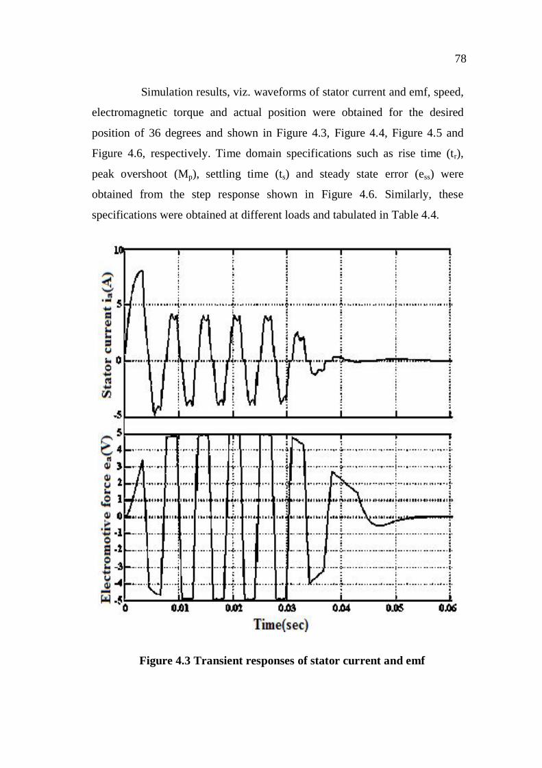
Simulation results, viz. waveforms of stator current and emf, speed,
electromagnetic torque and actual position were obtained for the desired
position of 36 degrees and shown in Figure 4.3, Figure 4.4, Figure 4.5 and
Figure 4.6, respectively. Time domain specifications such as rise time (tr),
peak overshoot (Mp), settling time (ts) and steady state error (ess) were
obtained from the step response shown in Figure 4.6. Similarly, these
specifications were obtained at different loads and tabulated in Table 4.4.
Figure 4.3 Transient responses of stator current and emf
79
Figure 4.4 Transient response of speed
Figure 4.5 Transient response of electromagnetic torque
80
Figure 4.6 Transient response of actual position
Table 4.4 Time domain specifications of ISE- based
PID controlled system
% of full load
KP Ki Kd tr
(sec) ts
(sec) MP
(%) ess
0 2.2 0.15 0.00001 0.0224 0.0348 0 0
10 2.43 0.12 0.00001 0.0234 0.0358 0 0
20 2.73 0.012 0.00003 0.0188 0.0361 0 0
30 3.05 0.0015 0.00005 0.0192 0.0362 0 0
40 3.38 0.0006 0.00008 0.0212 0.0371 0 0
50 3.75 0.00001 0.0001 0.0237 0.0378 0 0
60 4.63 0.00015 0.0075 0.0257 0.0397 0 0
70 5.53 0.0018 0.0043 0.0279 0.0412 0 0
80 6.17 0.045 0.0028 0.0292 0.0425 0 0
90 6.94 0.021 0.0014 0.0302 0.0433 0 0
100 7.8 0.1 0.001 0.0308 0.0443 0 0
81
Similarly, time domain specifications were obtained at different
loads from the transient response of output position and tabulated in
Table 4.5, Table 4.6, Table 4.7 and Table 4.8 for IAE, ITAE, ITSE and MSE,
respectively.
Table 4.5 Time domain specifications of IAE-based PID controlled
system
% of full
load
KP Ki Kd tr
(sec)
ts
(sec)
MP
(%)
ess
0 2.18 0.00028 0.000008 0.0218 0.0357 0 0
10 2.4 0.0002 0.000007 0.0185 0.0362 0 0
20 2.73 0.00016 0.000001 0.0192 0.0366 0 0
30 2.95 0.00014 0.00005 0.0198 0.0372 0 0
40 3.37 0.00013 0.0004 0.022 0.0376 0 0
50 3.67 0.0001 0.0001 0.025 0.0386 0 0
60 4.25 0.00005 0.00005 0.027 0.0407 0 0
70 4.76 0.00003 0.00003 0.029 0.0422 0 0
80 5.38 0.000007 0.000007 0.0305 0.0435 0 0
90 5.87 0.000003 0.000003 0.0311 0.0453 0 0
100 6.54 0.000001 0.00000001 0.0318 0.0461 0 0
82
Table 4.6 Time domain specifications of ITAE-based PID controlled