Preparatory Survey for Metropolitan Arterial Road Improvement Project Final Report 4-1 CHAPTER 4. ROAD AND STRUCTURE DESIGN 4.1 Road and Intersection Design 4.1.1 Design Criteria (1) Applicable Design Standards “Standard Specifications for geometric design of urban roads” published by the Directorate General of Highways of the Ministry of Public Works (MPW) in March 1992 is used as the main design standards for the road design. (2) Road Classification Roads in urban areas shall be classified into two types according to the kind of access control as follows. All roads in this project are defined as Type II. Type I : full access control Type II: partial access control or no access control Type II roads are classified into 4 classes according to their functional classification and design traffic volume. The design classes of Type II are shown in Table 4.1.1. Table 4.1.1 Design Classes of Type II Function Design traffic volume (PCU/day) Class Arterial I 10,000 or more I Primary Collector Less than 10,000 II 20,000 or more I Arterial Less than 20,000 II 6,000 or more II Collector Less than 6,000 III 500 or more III Secondary Local Less than 500 IV Source: Standard specifications for geometric design of urban roads, DGH Class I :The highest standard streets of 4 or more lanes to serve inter-city or intra-city, high speed, through traffic with partial access control Class II :High standard streets of 2 or more lanes to serve inter-city or intra-city, high speed, through traffic with/without partial access control Class III :Intermediate standard streets of 2 or more lanes to serve inter-district, moderate speed, through or access traffic without access control Class IV :Low standard streets of 1 travel way to serve access to the road side land lots (3) Design Speed The design speed of Type II shall be the value according to the class as follows. Class I : 60 km/h Class II : 60 or 50 km/h Class III : 40 or 30 km/h Class IV : 30 or 20 km/h
Transcript
Preparatory Survey for Metropolitan Arterial Road Improvement Project Final Report
4-1
CHAPTER 4. ROAD AND STRUCTURE DESIGN
4.1 Road and Intersection Design
4.1.1 Design Criteria
(1) Applicable Design Standards
“Standard Specifications for geometric design of urban roads” published by the Directorate General of Highways of the Ministry of Public Works (MPW) in March 1992 is used as the main design standards for the road design.
(2) Road Classification
Roads in urban areas shall be classified into two types according to the kind of access control as follows. All roads in this project are defined as Type II.
Type I : full access control
Type II: partial access control or no access control
Type II roads are classified into 4 classes according to their functional classification and design traffic volume. The design classes of Type II are shown in Table 4.1.1.
Table 4.1.1 Design Classes of Type II Function Design traffic volume (PCU/day) Class
Arterial I 10,000 or more I
Primary Collector
Less than 10,000 II 20,000 or more I Arterial
Less than 20,000 II 6,000 or more II Collector
Less than 6,000 III 500 or more III
Secondary
Local Less than 500 IV
Source: Standard specifications for geometric design of urban roads, DGH
Class I :The highest standard streets of 4 or more lanes to serve inter-city or intra-city, high speed, through traffic with partial access control
Class II :High standard streets of 2 or more lanes to serve inter-city or intra-city, high speed, through traffic with/without partial access control
Class III :Intermediate standard streets of 2 or more lanes to serve inter-district, moderate speed, through or access traffic without access control
Class IV :Low standard streets of 1 travel way to serve access to the road side land lots
(3) Design Speed
The design speed of Type II shall be the value according to the class as follows.
Class I : 60 km/h
Class II : 60 or 50 km/h
Class III : 40 or 30 km/h
Class IV : 30 or 20 km/h
Preparatory Survey for Metropolitan Arterial Road Improvement Project Final Report
4-2
(4) Geometric Design Criteria
Table 4.1.2 shows the geometric design criteria for each design speed.
Table 4.1.2 Geometric Design Criteria (Main road) Item Unit Design Standard
Design speed km/h 60 50 40 30 Road class I, II II III III, IV 1. Cross Section Lane Width m 3.5 3.25 3.25 (3.0) 3.25 (3.0)Median Width m 2.0 (1.0) 1.5 (1.0) 1.5 (1.0) 1.5 (1.0) Marginal Strip of Medians Width m 0.5 0.25 0.25 0.25 Left Shoulder Width m 2.0 (1.5) 2.0 (1.5) 2.0 (1.5) 0.5 Right Shoulder Width m 0.5 0.5 0.5 0.5 Planted Strip m 1.5 1.5 1.5 1.5 Frontage road m 4.0 4.0 4.0 4.0 Sidewalk m 3.0 (1.5) 3.0 (1.5) 1.5 (1.0) 1.5 (1.0) Cross Fall % 2 2 2. Horizontal Alignment Minimum Curve Radius m 400 (150) 150 (100) 100 (60) 65 (30) Minimum Radius at Normal Cross fall
m 2,000 (220)
1,300 (150)
800 (100)
500 (55)
Minimum Curve Length m 700/θ (100)
600/θ (80)
500/θ (70)
350/θ (50)
Minimum Transition Curve Length m 50 40 35 25 Minimum Radius Without Transition Curve
m 600 400 250 150
Minimum Stopping Sight Distance m 75 55 40 30 3. Vertical Alignment Maximum Grade % 5 6 7 8 Critical Vertical Curve Length m 300 (8%) 300 (9%) 200 (10%) - Minimum Crest Radius m 2,000
(1,400) 1,200 (800)
700 (450)
400 (250)
Minimum Sag Radius m 1,500 (1,000)
1,000 (700)
700 (450)
400 (250)
Minimum Curve Length m 50 40 35 25 Source: Standard specifications for geometric design of urban roads, DGH
Table 4.1.3 Geometric Design Criteria for At-grade Intersection Item Unit Design Standard
Design speed km/h 60 50 40 30 Road class I, II II III III, IV Minimum grade % 2 2 2 2 Minimum length of low grade m 40, 35 35 15 15, 6 Lane width of tangent section m 3.5, 3.25 3.25 3.25, 3.0 3.25, 3.0 Lane width of thru traffic lane m 3.25, 3.0 3.0, 2.75 3.0, 2.75 3.0, 2.75 Lane width of auxiliary lane m 3.25, 3.0,
2.75 3.25, 3.0,
2.75
Taper of lane shift 1/30 (40) 1/25 (35) 1/20 (30) 1/15 (25)Minimum length by deceleration m 30 20 15 10 Minimum length by shift m 30 25 20 15 Source: Standard specifications for geometric design of urban roads, DGH
Preparatory Survey for Metropolitan Arterial Road Improvement Project Final Report
4-3
Table 4.1.4 Geometric Design Criteria for Interchange Item Unit Design Standard
Design speed km/h 60 50 40 30 Road class I, II II III III, IV 1. Cross Section Lane Width m 3.5 3.5 3.5 3.5 Median Width m 2.0 2.0 2.0 2.0 Marginal Strip of Median Width m 0.5 0.5 0.5 0.5 Left Shoulder Width m 2.5 (0.75) 2.5 (0.75) 2.5 (0.75) 2.5 (0.75)Right Shoulder Width m 1.0 (0.75) 1.0 (0.75) 1.0 (0.75) 1.0 (0.75) 2. Horizontal Alignment Minimum Curve Radius m 140 (110) 90 (70) 50 (40) 40 (30) Minimum Parameter of Transition Curve
m 70 50 35 20
Minimum Transition Curve Radius m 350 220 140 140 Minimum Stopping Sight Distance m 75 55 40 35 3. Vertical Alignment Maximum Grade % 5 (up to 10) 5 (up to 10) 5 (up to 10) 5 (up to 10)Minimum Crest Radius m 1,400 800 450 250 Minimum Sag Radius m 1,000 700 450 250 Minimum Curve Length m 50 40 35 30 4. Deceleration Lane Standard Length of Deceleration Lane
m 70 50 30 -
Standard Taper Length in Parallel Type
m 45 40 40 -
5. Acceleration Lane Standard Length of Acceleration Lane
m 120 90 50 -
Standard Taper Length in Parallel Type
m 45 40 40 -
Source: Standard specifications for geometric design of urban roads, DGH
(5) Clearance
1) Road
The road clearance shall be provided according to the design of the cross section. No structure, facilities, trees or other unmovable objects can be placed within the clearance. The vertical and horizontal clearance is shown in Figure 4.1.1.
Source: Standard specifications for geometric design of urban roads, DGH
Figure 4.1.1 Vertical and Horizontal Clearance for Roads
Preparatory Survey for Metropolitan Arterial Road Improvement Project Final Report
4-4
2) Railways
The design criteria for railway crossings with roads is stipulated in the “Crossing and intersection of railway track construction (KM 53 OF 2000)” issued by the Ministry of transportation. The basic requirements for design of railway crossings are as follows.
At least 6.50 meters should be secured from the rail head.
The distance between the pier foundation and the center line of the rail track (single track) shall be at least 10 meters.
The pier foundation should be buried at least 1.50 meters below the ground surface.
4.1.2 Preliminary Design of Roads and Intersections
The preliminary design has been carried out for all potential projects to evaluate the feasibility of the projects and select the sub projects which will be analysed in more detail for the 2nd stage. Due to the lack of topographic maps and traffic data as of the 1st stage, the design is conducted based on satellite photos and site reconnaissance. In the existing investigations such as the feasibility study, basic design and detailed design implemented by the local or international consultants is referred to in the preliminary design.
After the sub projects are selected in the 1st stage, the design for sub projects will be revised and updated in accordance with the topographic and geographic surveys and the result of traffic analysis. The preliminary design of each potential project is described below.
(1) Semanggi
Semanggi is a clover-leaf type junction being composed of the following roads.
Table 4.1.5 Relevant Roads of Semanggi Intersection Road name Road class Lanes Design speed Administration
Several kinds of countermeasures can be considered for improvement of the junction. However, many difficulties are also expected in terms of the structure, traffic control and construction. Based on the site investigation, three alternatives are proposed as the structural improvement as shown in Table 4.1.6.
Preparatory Survey for Metropolitan Arterial Road Improvement Project Final Report
4-5
Table 4.1.6 Alternatives for the Improvement Plan of Semanggi Intersection Alternatives Outline
New construction of a flyover with 2 lanes in each direction outside Jl. Gatot Subroto for the merging lane to Jl. Sudirman
Congestion of the straight through lane will be eased because the straight through lane of Jl. Gatot Subroto can be separated from the merging lane.
1. Flyover on merging lane of Jl. Gatot Subroto
Removal of two out of the four existing loop ramps and construction of two direct ramps (Flyover) instead
Congestion of the straight through lane will be eased because the short weaving caused by two contiguous loop ramps which causes congestion of Jl. Gatot Subroto will be solved.
2. Installation of direct ramps
Construction of a straight through lane on the frontage road of Jl. Sudirman (It is impossible to go straight on the existing frontage road because it is divided by a junction.)
Connection between the merging lane of Jl. Gatot Subroto and Jl. Sudirman frontage road with a loop ramp
Congestion of the straight through lane will be eased because the merging ramp will not be connected to the straight through lanes of both roads.
3. Extension of frontage road of Jl. Sudirman
Source: JICA Survey Team
Jl. Sudirman
JIUT
Jl. G
atot
S
ubro
to
New Flyover
Closing the ramp
Jl. Sudirman
Jl. G
atot
S
ubro
to
New Flyover
Upgrading Ramp JIUT
Jl. Sudirman
JIUT
Jl. G
atot
S
ubro
to
Frontage road New Flyover
Upgrading ramp
Preparatory Survey for Metropolitan Arterial Road Improvement Project Final Report
4-6
For alternative 1 and 2, it is expected that the construction cost would be considerably high and take a long time for construction. On the other hand, the construction in alternative 3 is comparatively easy and the construction cost will be low. The image of alternatives 2 and 3 are as follows.
Source: JICA Survey Team
Figure 4.1.2 Image of Improvement for Semanggi Intersection Alternative 2
Source: JICA Survey Team
Figure 4.1.3 Image of Improvement for Semanggi Intersection Alternative 3
The method of improvement for Semanggi intersection needs to be studied based on not only the structural aspect but also the traffic analysis and environmental factors.
Taper and new slow lane for the access to loop ramp is constructed.
The loop ramp and the new slow lane are connected by the slight modification of vertical and horizontal alignment.
New slow lane is merged with the L-turn Ramp.
The existing slow lane is shifted next to the new slow lane
Main lane is isolated from the new slow lane
Same as other side L-turn ramp
New slow
L-turn ramp
Jl. Sudirman
Jl. Gatot Subroto
Loop Ramp
Existing slow lane
Preparatory Survey for Metropolitan Arterial Road Improvement Project Final Report
4-7
(2) Margonda Cinere
No specific study or design work has been conducted for this intersection. An underpass for both Jl. Margonda and Bogor railway line is proposed in the east-west direction next to JORR2. This design can achieve the grade separation not only at the intersection but also at the railway crossing point which is a request from DGR. It is difficult to propose the grade separation on Jl. Margonda because of planed JORR2.
However there are some issues raised with this design. The underpass will not function without road improvement on the west side where there is no existing road at present.
In addition, the output from the underpass construction will be affected as the traffic flow will be drastically changed by JORR2. However, even through JORR2 was proposed more than 10 years ago, the implementation schedule is still uncertain due to the land acquisition issue. Considering the construction method as well, it is desirable that the construction of the underpass will be implemented simultaneously or after the JORR2 construction.
Table 4.1.7 Relevant Roads of Margonda Cinere Road name Road class Lanes Design speed Administration
Jl. Margonda Type-II/Class-I 3x2 60km/h National road (DGH)
Jl. Ir H. Juanda Type-II/Class-I 2x2 60km/h National road (DGH) Source: DGH
Table 4.1.8 Project Condition of Margonda Cinere
Structure type Underpass (Jl. Juanda and railway line)
Approximate length of structure 760m
Main road 2 lanes each way with median (W=22.0m) Number of lanes
Frontage road 1 lane each way
Existing study None
Railway crossing Bogor railway line
Issues Conflict with other project (JORR2) Source: JICA Survey Team
Source: JICA Survey Team
Figure 4.1.4 Plan of Improvement for Margonda Cinere
Preparatory Survey for Metropolitan Arterial Road Improvement Project Final Report
4-8
(3) Cililitan
The detailed design for an underpass in the east-west direction was already conducted by DGH in 2007. As the elevation around the intersection is higher than the surrounding area, an underpass is more suitable than an overpass. A pumping system for drainage must be provided for the underpass structure. The road on the east side, Jl. Cililitan Besar, which has only two narrow lanes needs to be improved for functioning in the trunk road network. The clearance with the canal to the west should be considered.
In terms of the underpass in the north-south direction, buried cables are an obstacle for construction. The replacement of existing bus way shelters and the pedestrian deck near the intersection is also necessary.
Table 4.1.9 Relevant Roads of Cililitan Road name Road class Lanes Design speed Administration
Jl. Jend Sutoyo Type-II/Class-I 3x2 60km/h National road (DGH)
Jl. Raya Bogor Type-II/Class-I 2x2 60km/h National road (DGH)
Jl. Cililitan Besar Type-II/Class-II 1x2 40km/h Provincial road (DKI)
Structure type Underpass (Jl. Dewi Sartika and Jl. Cililitan Besar)
Approximate length of structure 430m
Main road 1 lane each way (W=13.0m) Number of lanes
Frontage road 1 lane each way
Existing study D/D (DGH:2007)
Railway crossing None
Issues Widening the Jl. Cililitan Besar Source: JICA Survey Team
Source: JICA Survey Team
Figure 4.1.5 Plan of Improvement for Cililitan
Preparatory Survey for Metropolitan Arterial Road Improvement Project Final Report
4-9
(4) R.E. Martadinata
The detailed design was conducted in the scheme of the project for Tanjung Priok Access Road (TgPA) in 2007. However, the construction of section W1 for TgPA is not yet started because of the escalated project cost. Therefore, the construction of the flyover was also cancelled for the same reason.
The 4-lane flyover over the bus terminal and railway track was proposed in the detailed design. The clearance for the railway track was secured according to the railway regulation but it is necessary to review the design since DGR has a plan to develop and extend the railway track. The bus terminal, which is severely congested by the conflict between through traffic and long-distance buses, needs to be developed in accordance with the flyover construction. Compatibility with the port access flyover proposed by PERIND2 was already coordinated in the detailed design.
It is anticipated that the construction will be quite difficult because the road is congested all the time and there are many illegally occupied shops around the bus terminal. Also, a countermeasure for the ground subsidence needs to be considered because subsidence has caused the road in front of the port to become undulated. The port gate at the west side of the bus terminal will be closed after the construction of the flyover.
Table 4.1.11 Relevant Roads of R.E. Martadinata Road name Road class Lanes Design speed Administration
Jl. Enggano Type-II/Class-II 2x2 60km/h National road (DGH)
Jl. Martadinata Type-II/Class-I 2x2 60km/h National road (DGH) Source: DGH
Table 4.1.12 Project Condition of R.E. Martadinata
Structure type Overpass (Jl. Martadinata)
Approximate length of structure 810m
Main road 2 lanes each way (W=9.5m x 2) Number of lanes
Frontage road 1 lane each way
Existing study D/D (2007: DGH)
Railway crossing Tanjung Priok railway line
Issues Coordination with bus terminal and railway station Source: JICA Survey Team
Source: JICA Survey Team
Figure 4.1.6 Plan of Improvement for R.E. Martadinata
Preparatory Survey for Metropolitan Arterial Road Improvement Project Final Report
4-10
(5) Sulawesi - Tg.PA
The same as Martadinata, the detailed design was conducted in the scheme of the project for Tanjung Priok Access Road (TgPA) in 2007 and the construction of the flyover was removed from the loan package. The construction of TgPA N-S section above this intersection will be commenced within 2011.
A 2-lane flyover and frontage road parallel to TgPA was proposed. The length of the flyover will be long due to providing a U-turn lane. The right of way for the flyover and frontage road was secured within the scheme of the TgPA project.
As the arterial road will be cut at the railway crossing point, the vehicles from Jl. Enggano have to be diverted using a U-turn.
Table 4.1.13 Relevant Roads of Sulawesi - Tg.PA Road name Road class Lanes Design speed Administration
Jl. Sulawesi Type-II/Class-I 3x2 60km/h National road (DGH)
Jl. Yos Sudarso Type-II/Class-I 3x2 60km/h National road (DGH)
Jl. Enggano Type-II/Class-II 2x2 40km/h National road (DGH)
Jl. Pelabuhan Raya Type-II/Class-I 3x2 60km/h National road (DGH) Source: DGH
Table 4.1.14 Project Condition of Sulawesi - Tg.PA
Structure type Overpass (Jl. Yos Sudarso and Jl. Sulawesi)
Approximate length of structure 740m
Main road 2 lanes each way (W=9.5m x 2) Number of lanes
Frontage road 2 lanes each way
Existing study D/D (2007: DGH)
Railway crossing Tanjung Priok railway line
Issues Source: JICA Survey Team
Source: JICA Survey Team
Figure 4.1.7 Plan of Improvement for Sulawesi - Tg.PA
Preparatory Survey for Metropolitan Arterial Road Improvement Project Final Report
4-11
(6) Latumentan
No study or design work has been conducted for this intersection. Two lane flyovers and frontage road with 1-lane for each direction are proposed as the grade separation for the railway crossing. The existing road on Jl. Makaliwe from the north passes between the piers of the bridge of JIUT so that the vertical and horizontal clearance needs to be carefully confirmed. The busway shelter will be relocated to the outside of the flyover section. According to DGR, as the improvement for double track to north side at this point will be started within 2011, the design must consider the clearance to provide enough width.
An underpass has also been considered but there are many difficulties for construction because of the underground foundations of the pier for JIUT.
In addition, there is a plan to underpass the railway in the future in accordance with the development of the MRT East-West line. If it is implemented, the flyover will be useless.
Table 4.1.15 Relevant Roads of Latumentan Road name Road class Lanes Design speed Administration
Jl. Dr Makaliwe Type-II/Class-I 2x1 60km/h Provincial road (DKI)
Structure type Overpass (Jl. Makaliwe and Jl. Satria)
Approximate length of structure 500m
Main road 2 lanes each way (W=9.5m x 2) Number of lanes
Frontage road 1 lane each way
Existing study None
Railway crossing Tangerang railway line
Issues Conflict with other project (MRT) Replacement of bus shelter
Source: JICA Survey Team
Source: JICA Survey Team
Figure 4.1.8 Plan of Improvement for Latumentan
Preparatory Survey for Metropolitan Arterial Road Improvement Project Final Report
4-12
(7) Sudirman - Daan Mogot
A 4-lane flyover with 2-lane frontage roads is proposed over 2 existing roads in the east-west direction with the river bridge on Jl. Sudirman and Jl. Pembangunan 3. It would be difficult to construct an underpass due to the river crossing. The existing bridge will be replaced based on the alignment of the frontage road. Both of the schools located near Jl. Sudirman will be control points for setting the alignment.
It is necessary to widen Jl. Pembangunan 3, which is currently a narrow 2-lane up to the international airport to avoid its becoming a bottleneck.
Table 4.1.17 Relevant Roads of Sudirman - Daan Mogot Road name Road class Lanes Design speed Administration
Table 4.1.18 Project Condition of Sudirman - Daan Mogot
Structure type Overpass (Jl. Sudirman and Jl. Pembangunan 3)
Approximate length of structure 550m
Main road 2 lanes each way with median (W=17.6m) Number of lanes
Frontage road 1 lane each way
Existing study D/D (2008: Banten Province)
Railway crossing None
Issues Widening of Jl. Pembangunan 3 Source: JICA Survey Team
Source: JICA Survey Team
Figure 4.1.9 Plan of Improvement for Sudirman - Daan Mogot
Preparatory Survey for Metropolitan Arterial Road Improvement Project Final Report
4-13
(8) Kuningan
A feasibility study was conducted by DGH and an underpass on Jl. Rasuna Side was selected as the best alternative. It is impossible to apply a flyover because of the elevated toll road.
The total length of the underpass will reach about 650m to cover Jl. Gatot Subroto. The main road will consist of three lanes each way, plus a busway, additionally, 2 lane frontage roads will be provided on each side for the entire section. As the underpass will be constructed under the elevated structures of JIUT and Jl. Kapten Tendean, it is necessary to consider the construction method for safety.
The busway shelters and the pedestrian decks presently located near both intersections need to be relocated to the outside of the underpass section.
Table 4.1.19 Relevant Roads of Kuningan Road name Road class Lanes Design speed Administration
Jl. Gatot Subroto Type-II/Class-I 3x2 60km/h National road (DGH)
Jl. Rasuna Said Type-II/Class-II 3x2 60km/h Provincial road (DKI)
Jl. Kapten Tendean Type-II/Class-II 2x2 60km/h Provincial road (DKI)
Structure type Underpass (Jl. Rasuna Said and Jl. Mampang Praratan)
Approximate length of structure 940m
Main road 2 lanes each way plus a busway with median (W=29.0m) Number of lanes
Frontage road 2 lanes each way
Existing study F/S (2006: DGH)
Railway crossing None
Issues Relocation of bus shelter Source: JICA Survey Team
Source: JICA Survey Team
Figure 4.1.10 Plan of Improvement for Kuningan
Preparatory Survey for Metropolitan Arterial Road Improvement Project Final Report
4-14
(9) Pancoran
No study or design work has been conducted for Pancoran intersection. A flyover with 2-lanes and a 2-lane frontage road on the west bound side of the same type as on the opposite side is proposed. As a high-rise building is near the existing road, the alignment and road width will be carefully designed for avoiding compensation. The On ramp for JIUT, 300m to the west of the intersection, is also a control point.
The busway shelter must be relocated when the flyover is constructed. If the shelter is shifted to under the new flyover, the bus way will pass on the frontage road. It is almost impossible to raise the busway shelter to the same level as flyover due to the restriction of the alignment of JIUT.
Table 4.1.21 Relevant Roads of Pancoran Road name Road class Lanes Design speed Administration
Jl. Gatot Subroto Type-II/Class-I 3x2 60km/h National road (DGH) Jl. Raya Pasar Minggu
Main road 2 lanes for 1 direction (East to West) (W=9.5m) Number of lanes
Frontage road 1 lane
Existing study None
Railway crossing None
Issues Land acquisition Source: JICA Survey Team
Source: JICA Survey Team
Figure 4.1.11 Plan of Improvement for Pancoran
Preparatory Survey for Metropolitan Arterial Road Improvement Project Final Report
4-15
(10) Cilandak
No study or design work has been conducted for Cilandak intersection. Considering the terrain condition, an underpass with 2 lanes each way at the same level as JORR and a frontage road with 1-lane in each direction are proposed. The specific geometric issues are not known but the construction of the underpass and box culverts adjacent to the existing retaining wall for JORR seems as though it would be difficult.
Table 4.1.23 Relevant Roads of Cilandak Road name Road class Lanes Design speed Administration
Jl. Ampera Raya Type-II/Class-II 1x2 60km/h Provincial road (DKI)
Jl. TB Simatupang Type-II/Class-I 2x2 60km/h National road (DGH)
JORR Type-I/Class-I 3x2 80km/h Toll road (Jalan Lingrar luar Jakarta)
Source: DGH
Table 4.1.24 Project Condition of Cilandak
Structure type Underpass (Jl. TB Simatupang)
Approximate length of structure 370m
Main road 2 lanes each way (W=10.5m x 2) Number of lanes
Frontage road 1 lane each way
Existing study None
Railway crossing None
Issues Construction difficulty Source: JICA Survey Team
Source: JICA Survey Team
Figure 4.1.12 Plan of Improvement for Cilandak
Preparatory Survey for Metropolitan Arterial Road Improvement Project Final Report
4-16
(11) Fatmawati
No study or design work has been conducted for Fatmawati intersection. A flyover with 2 lanes each way and frontage road with 1-lane each way are proposed for Jl. TB Simatupang. It is necessary to consider the clearance with the houses, buildings and the gas station at the south side of the road.
The specific geometric issues are not known. But the most significant issue is the MRT which is planned to pass over the JORR. The basic design was completed and the detailed design will start in 2011 after the tender evaluation.
It is better to postpone the construction of the flyover until the MRT opens because the adjustment with the MRT will be difficult and the traffic flow is expected to change due to the transportation development.
Table 4.1.25 Relevant Roads of Fatmawati Road name Road class Lanes Design speed Administration
Jl. TB Simatupang Type-II/Class-I 2x2 60km/h National road (DGH)
JORR Type-I/Class-I 3x2 80km/h Toll road (Jalan Lingrar luar Jakarta)
Source: DGH
Table 4.1.26 Project Condition of Fatmawati
Structure type Overpass (Jl.TB Simatupang)
Approximate length of structure 450m
Main road 2 lanes each way (W=9.5m x 2) Number of lanes
Frontage Road 1 lane each way
Existing study None
Railway crossing None
Issues Conflict with other project (MRT) Source: JICA Survey Team
Source: JICA Survey Team
Figure 4.1.13 Plan of Improvement for Fatmawati
Preparatory Survey for Metropolitan Arterial Road Improvement Project Final Report
4-17
(12) Ciawi - Bogor
No study or design work has been conducted for Ciawi-Bogor intersection. A flyover with 2-lanes and frontage road on Jl. Raya Sukabumi is proposed. The alignment of the flyover is curved following along the existing road. Jl. Raya Sukabumi on the south side of the intersection is a narrow 2-lane so it could be a bottleneck.
There are two development plans in the area, the Rencana Jalan Toll (extension of Jagorawi Toll Road) and Bogor Ring Road. Much traffic will be diverted to them and the traffic condition will be changed after the construction of both roads.
Table 4.1.27 Relevant Roads of Ciawi - Bogor Road name Road class Lanes Design speed Administration
Jl. Raya sukabumi Type-II/Class-I 1x2 60km/h National road (DGH)
Jl. Raya Ciawi Type-II/Class-I 2x2 60km/h National road (DGH)
Main road 2 lanes each way with median (W=17.6m) Number of lanes
Frontage road 1 lane each way
Existing study None
Railway crossing None
Issues Conflict with other projects (Jagorawi Toll road and Bogor Ring Road)
Source: JICA Survey Team
Source: JICA Survey Team
Figure 4.1.15 Plan of Improvement for Ciawi – Bogor
Bogor Ring Road Access
Rencana Jalan Toll
Figure 4.1.14 Road Development Plan (Ciawi)
Project Site
Preparatory Survey for Metropolitan Arterial Road Improvement Project Final Report
4-18
(13) Pinang Baris
The detailed design of a 4-lane flyover with a 2-lane frontage road on the each side on Jl. Gatot Subroto was completed for Pinang Baris intersection by DGH. The road width and alignment should be designed taking into consideration the right of way because many houses and buildings are settled along the existing road. The bridge and clock tower at the west side of the intersection are control points for the road design.
Table 4.1.29 Relevant Roads of Pinang Baris Road name Road class Lanes Design speed Administration
Jl. Gatot Subroto Type-II/Class-I 2x2 60km/h National road (DGH)
Main road 2 lanes each way with median (W=17.6m) Number of lanes
Frontage road 1 lane each way
Existing study D/D (2007: DGH)
Railway crossing None
Issues Land acquisition Source: JICA Survey Team
Source: JICA Survey Team
Figure 4.1.16 Plan of Improvement for Pinang Baris
Preparatory Survey for Metropolitan Arterial Road Improvement Project Final Report
4-19
(14) Asrama - Gatot Subroto
No study or design work has been conducted for Asrama-Gatot Subroto intersection. A 4-lane flyover with 2-lane frontage road for Jl. Gagak Hitam, Medan Ring Road, is proposed. The intersection is already improved with an exclusive left-turn lane split by a traffic island.
The specific geometric issues are not known as it is a simple cross intersection. The grade separation on Medan Ring Road is the strategy for Medan development.
Table 4.1.31 Relevant Roads of Asrama - Gatot Subroto
Road name Road class Lanes Design speed Administration
Jl. Gatot Subrot Type-II/Class-I 2x2 60km/h National road (DGH)
Jl. Asrama Type-II/Class-I 2x2 60km/h National road (DGH)
Jl. Gagak Hitam Type-II/Class-I 2x2 60km/h National road (DGH) Source: DGH
Table 4.1.32 Project Condition of Asrama - Gatot Subroto
Structure type Overpass (Jl. Gagak Hitam)
Approximate length of structure 530m
Main road 2 lanes each way with median (W=17.6m) Number of lanes
Frontage road 1 lane each way
Existing study None
Railway crossing None
Issues Source: JICA Survey Team
Source: JICA Survey Team
Figure 4.1.17 Plan of Improvement for Asrama - Gatot Subroto
Preparatory Survey for Metropolitan Arterial Road Improvement Project Final Report
4-20
(15) Katamso
A 4-lane underpass on Jl. AH Nasution is proposed in the feasibility study conducted by DGH. In the F/S, the total length of the underpass reaches 1.0km due to covering both intersections and the single track railway which is about 400m to the east.
According to the site investigation, the underpass is proposed only for the intersection because the railway is currently not in operation and the reactivation schedule is uncertain. It is possible to extend the underpass structure for the railway in the future.
The distance between the river and the intersection is critical for vertical alignment because it is only about 140m which is short to secure the required gradient.
Table 4.1.33 Relevant Roads of Katamso
Road name Road class Lanes Design speed Administration
Jl. AH Nasution Type-II/Class-I 2x2 60km/h National road (DGH)
Main road 2 lanes each way with median (W=22.0m) Number of lanes
Frontage road 1 lane each way
Existing study F/S (2010: DGH)
Railway crossing None (400m from Non-operation railway on East)
Issues Distance to the river (East) Source: JICA Survey Team
Source: JICA Survey Team
Figure 4.1.18 Plan of Improvement for Katamso
Preparatory Survey for Metropolitan Arterial Road Improvement Project Final Report
4-21
(16) Sudirman II
No study or design work has been conducted for Sudirman II intersection. A 4-lane flyover with 2-lane frontage roads is proposed over the T-shaped intersection and railway crossing. As the Tangerang railway will be developed for double tracks to the south side, the vertical alignment will be decided considering the clearance.
After the flyover is constructed, the frontage road ends at the railway crossing and will be provided with a U-turn lane. The bus way and shelter around the flyover will also be changed.
Table 4.1.35 Relevant Roads of Sudirman II Road name Road class Lanes Design speed Administration
Jl. Sudirman Type-II/Class-I 4x2 60km/h National road (DGH)
Main road 2 lanes each way with median (W=17.6m) Number of lanes
Frontage road 1 lane each way
Existing study None
Railway crossing Tangerang railway line
Issues Source: JICA Survey Team
Source: JICA Survey Team
Figure 4.1.19 Plan of Improvement for Sudirman II
(17) Cikarang
Cikarang project is composed of improvement of Jl. Raya Kalimalang and 3 local roads crossing Cikampek Toll Road in the north-south direction.
1) Jl. Raya Kalimalang
According to the site investigation, the proposed upgrade is for rigid pavement for the 2-lane, 7.3km long Jl. Raya Kalimalang from the intersection with Jl. Access from Toll Cibitung to Jl. Cibarusah is preferable for prompt implementation because there are pipelines along the road for the entire section and some houses remain adjacent to the road. The intersection for
Preparatory Survey for Metropolitan Arterial Road Improvement Project Final Report
4-22
Jl Cibarusah will be improved with grade separation by the application of a 2-lane flyover on Jl. Kalimalang.
The widening to 4-lanes for 13km of Jl. Kalimalang from Jl. Access from Toll Cibitung to Jl. Tegal Cadas is proposed as a future development. At that time, it will be necessary to acquire additional land, replace the pipeline, improve the intersection, widen the flyover on Jl. Cibarusah and expand the existing bridge on Cikarang River.
2) Jl. Bari-Cibitung
The scope of this project is about 1.3km of road improvement and bridge construction on the toll road. As the 2-lane road surface is damaged in some parts, repair with rigid pavement is required. The bridge with 1.5-lanes above Cikampek Toll Road will be widened to 2-lanes by the construction of a new bridge to avoid the bottleneck on the current bridge.
3) Jl. Imam Bonjol 4
The scope of the project is about 1.6km of road improvement and bridge construction over Kalimalang River. The existing bridge of Jl. Imam Bonjol 4 over the river is old and not wide enough. In addition, as the road alignment is not smooth enough for a trunk road, the alignment is to be modified and a new bridge is to be constructed on the new alignment. A part of the road surface on Jl. Imam Bonjol 4 needs to be improved. The bridge on Cikampek Toll Road will remain so that it has 2 adequate lanes.
4) Dry Port Access Road
The construction of a dedicated road, the Dry Port Access Road, connecting the new interchange around the 29km post on Cikampek Toll Road and the Dry Port is on-going. This road is scheduled to open in the beginning of 2012.
A new road is proposed to connect this road with the industrial area to the south of Cikampek Toll Road. According to Jababeka, which designed and constructed the Dry Port Access Road, this road is dedicated for the cargo trucks and is not considered as access to the southern area of the industrial area as of now. The intersection for the Dry Port Access Road with the new road to the southern area should be located outside of the new toll gate to control the traffic. As there are many issues for the road and bridge construction, traffic management and land acquisition, a solution should be found based on the discussions by the stakeholders, such as DGH, each industrial park and Bekasi Regency.
The plan of the Dry Port Access Road and candidate new road is shown in Figure 4.1.23.
Table 4.1.37 Relevant Roads of Cikarang Road name Road class Lanes Design speed Administration
Jl. Raya Kalimalang Type-II/Class-III 2x1 40km/h Provincial road (Bekasi)
Main road Jl. Kalimalang: 1 lane each way (W=14.0m) Other roads: 1 lane each way (W=8.0m) Number of lanes
Frontage road -
Preparatory Survey for Metropolitan Arterial Road Improvement Project Final Report
4-23
Existing study None
Railway crossing None
Issues Land acquisition Coordination with Dry Port Access Road plan
Source: JICA Survey Team
Source: JICA Survey Team
Figure 4.1.20 Plan of Improvement for Cikarang
Source: JICA Survey Team
Figure 4.1.21 Plan of Improvement for Jl. Bali-Cibitung
Cibitung IC
Bridge construction(1.5-lane at present)
Jl. Kalimalang
Jl. Bali-Cibitung Road rehabilitation
Preparatory Survey for Metropolitan Arterial Road Improvement Project Final Report
4-24
Source: JICA Survey Team
Figure 4.1.22 Plan of Improvement for Jl. Imam Bonjol 4
Source: JICA Survey Team
Figure 4.1.23 Plan of Improvement Dry Port Access Road
(18) Senayan
No study or design work has been conducted for Senayan intersection. In order to separate the traffic from Jl. Patimura to Jl. Sudirman away from the roundabout, a 2-lane flyover in one direction is proposed above the roundabout. The flyover passes over within the area of road property to avoid land acquisition and the distance between the flyover and the statue next to the pond is about 40m.
Bridge construction
Jl. Kalimalang
Road improvement (1.6km)
Road re-alignment
Jl. Iman Bonjol 4
Existing 2-lanes bridge
Dry Port Access Road
Jababeka
Lippo
New IC (29km)
Preparatory Survey for Metropolitan Arterial Road Improvement Project Final Report
4-25
As Jl. Patimura is narrow to accommodate the flyover and 1-lane frontage road, the width of the flyover with frontage needs to be diminished as much as possible. The frontage road of Jl. Sudirman is shifted to the outside because the flyover merges next to the left side of the fast lane.
The busway shelter needs to be shifted depending on the alignment of the flyover.
Table 4.1.39 Relevant Roads of Senayan Road name Road class Lanes Design speed Administration
Structure type Overpass (Jl. Sudirman to Jl. Patimura)
Approximate length of structure 730m
Main road 2 lanes for 1 direction (W=9.5m) Number of lanes
Frontage road 1 lane
Existing study None
Railway crossing None
Issues Land acquisition Clearance with the statue
Source: JICA Survey Team
Source: JICA Survey Team
Figure 4.1.24 Plan of Improvement for Senayan
Preparatory Survey for Metropolitan Arterial Road Improvement Project Final Report
4-26
4.1.3 Summary of Preliminary Design
The summary of preliminary design is shown in Table 4.1.41.
Note that the information will be revised by the result of the study in the 2nd stage. Especially, the improvement method for Semanggi will be determined based on the traffic analysis and the structure length will be varied after setting of the vertical alignment and the bridge design.
Table 4.1.41 Summary of Preliminary Design Approx.
structure length Number of lanes
and width Potential projects FO/UP Overall Bridge
Main road
Frontage road
Existing study
RailwayCrossing
1 Semanggi - - - - -
2
Margonda Cinere
UP 760m - 2x2
(22.0m)1 ●
3 Cililitan UP 430m - 1x2
(13.0m)1
D/D (2007)
4
R.E. Martadinata
FO 570m 370m2x2
(19.0m)1
D/D (2007)
●
5
Sulawesi - Tg.PA
FO 550m 350m2x2
(19.0m)2
D/D (2007)
●
6 Latumenten FO 500m 270m2x2
(19.0m)1 ●
7
Sudirman-Daan Mogot
FO 550m 300m2x2
(17.6m)2
D/D (2008)
8 Kuningan UP 940m - 2x2
(22.0m)1
F/S (2006)
9 Pancoran FO 530m 270m2x1
(9.5m)1
10 Cilandak UP 370m - 2x2
(21.0m)1
11 Fatmawati FO 450m 250m2x2
(19.0m)1
12 Ciawi-Bogor FO 540m 290m2x2
(17.6m)1
13 Pinang Baris FO 540m 220m2x2
(17.6m)1
D/D (2007)
14
Asrama-Gatot Subroto
FO 530m 280m2x2
(17.6m)1
15 Katamso UP 280m - 2x2
(22.0m)1
F/S (2010)
16 Sudirman II FO 550m 300m2x2
(17.6m)1 ●
17 Cikarang 1 EW road 3 NS road
7.3km 450m1x2
(14.0m)-
18 Senayan FO 730m 380m2x1
(9.5m)1
Source: JICA Survey Team Note: The figure in the “number of lanes on main road” shows the number of lanes and directions
Preparatory Survey for Metropolitan Arterial Road Improvement Project Final Report
4-27
4.1.4 Basic Design of Roads and Intersections
The basic design of roads and intersections is conducted for 10 sub-projects selected in the 1st stage. First of all, the preliminarily designs are reviewed based on the topographic condition, traffic analysis and discussion with the MPW and DKI. The basic design is carried out and the drawings are prepared for the most suitable plan. The list of sub-projects is shown in Table 4.1.42.
Table 4.1.42 List of Sub-projects
Sub-projects Location Existing study Railway crossing
1 Semanggi DKI
4 R.E. Martadinata DKI D/D (2007) ●
5 Sulawesi - Tg.PA DKI D/D (2007) ●
8 Kuningan DKI F/S (2006)
9 Pancoran DKI
13 Pinang Baris Medan D/D (2007)
15 Katamso Medan F/S (2010)
16 Sudirman II Tangerang City ●
17 Cikarang Bekasi Regency
18 Senayan DKI
Source: JICA Survey Team
The design concept for each sub-project including the improvement method, the control points, the alignment and the number of lanes and the structure type which are determined after a series of discussions with the MPW and local governments are described as follows. A set of drawings are attached in the Appendix.
The design criteria for the preliminary design described in 4.1.1 is applied on the basic design as well.
(1) Semanggi
1) Study of suitable improvement
a) Alternatives
As Semanggi intersection is located in the midst of a metropolitan area, the improvement needs to be basically conducted in the area of the road and intersection property to avoid land acquisition. According to the site investigation, the following 5 alternatives are proposed.
Alternative 1: Construction of additional lanes along Jl. Gatot Subroto (Bridge)
Main point of alternative 1 is to provide a new lane along and outside of Jl. Gatot Subroto which is constructed with a bridge and high embankment. The plan is shown in Figure 4.1.25.
Traffic capacity of Jl. Gatot Subroto will increase and the weaving section for the loop ramps could be isolated from the main traffic, which are the positive impacts. On the other hand, as it is difficult to make the elevation of the existing and new lane the same level because of the rigid structure of the existing bridge, traffic congestion may occur on the new lane with the 1-lane split from the existing lane. Furthermore, the radius of the loop ramp will be smaller which threatens the traffic safety.
Preparatory Survey for Metropolitan Arterial Road Improvement Project Final Report
4-28
Taper and new slow lane for the access to loop ramp is constructed.
The loop ramp and the new slow lane are connected by the slight modification of vertical and horizontal alignment.
New slow lane is merged with the L-turn ramp.
Main lane is isolated from the new slow lane.
L-turn ramp
L-turn ramp
Jl. Sudirman
Jl. Gatot Subroto
Loop Ramp
Existing slow lane
From Jl. Sudirmanto Jl. Gatot Subroto
From Jl. Sudirmanto Jl. Gatot Subroto
From Jl. Gatot Subrototo Jl. Sudirman
From Jl. Gatot Subrototo Jl. Sudirman
Weaving SectionWeaving Section
Source: JICA Survey Team
Figure 4.1.25 Plan of Alternative 1
Alternative 2-1: Improvement of slow lane and loop ramp (At-grade)
In contrast to Alternative 1, Alternative 2-1 is the plan to resolve the weaving section on Jl. Sudirman as shown in Figure 4.1.26. The main point is that the slow lane and left turn ramp from Jl. Sudirman to Jl. Gatot Subroto are merged and the slow lane in the junction connects directly to the existing loop ramp. The right turn traffic from Jl. Sudirman to Jl. Gatot Subroto passes through the slow lane and the loop ramp. The existing traffic flow from the main lane of Jl. Sudirman to the loop ramp will be closed but U-turn traffic from Jl.Gatot Subroto could still use the same route as now.
By this improvement, the weaving section on Jl. Sudriman disappears which seems to be a significant improvement to mitigate the congestion. On the other hand, it will be a main concern that the turning traffic from Jl. Sudirman is mixed with the motorbike and local bus traffic on the same route.
L-turn rampSlow lane
L-turn ramp
Jl. Sudirman
Jl. Gatot Subroto
Loop Ramp
Existing slow lane
From Jl. Sudirmanto Jl. Gatot Subroto
From Jl. Gatot Subrototo Jl. Sudirman
To Monas
To Senayan
The box culvert and slow lane are expanded to secure the enough two lanes
Main lane is isolated from existing diverted ramp.(Only U-turn traffic from Jl.Gatot Subroto can be merged)
New exclusive lane is merged with the loop ramp
The slow lane is separated to the existing slow lane and loop ramp.
The existing ramp should be same level as the slow lane.
Weaving SectionWeaving SectionThe median between the fast and slow lanes are closed.
Source: JICA Survey Team
Figure 4.1.26 Plan of Alternative 2-1
Preparatory Survey for Metropolitan Arterial Road Improvement Project Final Report
4-29
Alternative 2-2: Improvement of slow lane and loop ramp (At-grade)
This plan is modified from Alternative 2-1. The left turn ramp from Jl.Sudirman to Jl. Gatot Subroto is closed and changed to a ramp for right turns which connects to the loop ramp. To secure the vertical clearance of the new ramp with the existing loop ramp, the radius of the loop ramp is made bigger and the new ramp is located lower than the ground level.
In this improvement, the left turn ramp is merged into the slow lane. To utilize the existing box culvert, the gradient of the slow lane remains about 8% which is very steep for the left turn ramp. As the elevation of the new ramp is lower than the ground level, it is necessary to provide a water pump to drain the rain water.
New ramp Slow lane
L-turn ramp
Jl. Sudirman
Jl. Gatot Subroto
New loop RampExisting slow lane
From Jl. Sudirmanto Jl. Gatot Subroto
From Jl. Gatot Subrototo Jl. Sudirman
To Monas
To Senayan
Control the traffic from mainline. (Eg. Only allow U-turn traffic from Jl.GatotSubroto to enter the ramp)
New exclusive lane is to be connected with the exisitng loop ramp using R≒30m Close the left –turn ramp
Keep the existing slow lane separted from the new exclusive ramp
Gradient of existing slow lanes is 8-9%.
Keep the exisiting box culvert for exclusive for slow lane traffic
Close the opening between the fast and slow lanes.
Weaving SectionWeaving Section
Close the opening between the fast and slow lanes.
Source: JICA Survey Team
Figure 4.1.27 Plan of Alternative 2-2
Alternative 3: Construction of additional lanes along Jl. Sudirman (At-grade)
Like Alternative 2-2, a new lane for Jl. Sudirman is provided. The new lane is completely isolated from the existing main lane and passes under the next span of Jl. Gatot Subroto from the main lane due to the V-shape of the existing pier.
The weaving section which is one of the reasons of traffic congestion is shifted on to the new lane. Therefore, the congestion on Jl. Sudirman for through traffic will be alleviated. However, it is expected that the traffic lane from the weaving section on the new lane will continue to the main lane. In addition, the connection of the loop ramp and the new lane needs to be changed to a smaller curve. The existing slow lane under the bridge will be shifted to make the space for the 2 new lanes.
Preparatory Survey for Metropolitan Arterial Road Improvement Project Final Report
4-30
Taper and new slow lane for the access to loop ramp is constructed.
The loop ramp and the new slow lane are connected by the slight modification of vertical and horizontal alignment.
New slow lane is merged with the L-turn lamp.
The existing slow lane is shifted next to the new slow lane.
Main lane is isolated from the new slow lane.
L-turn ramp
New slow lane
L-turn ramp
Jl. Sudirman
Jl. Gatot Subroto
Loop Ramp
Existing slow lane
From Jl. Sudirmanto Jl. Gatot Subroto
From Jl. Sudirmanto Jl. Gatot Subroto
From Jl. Gatot Subrototo Jl. Sudirman
From Jl. Gatot Subrototo Jl. Sudirman
Weaving SectionWeaving Section
Source: JICA Survey Team
Figure 4.1.28 Plan of Alternative 3
Alternative 4: Construction of new loop ramps (Flyover)
Unlike the other alternatives, this is a dynamic improvement plan. A new loop ramp on a flyover from Jl. Gatot Subroto to Jl. Sudirman will be constructed above the intersection. The plan is shown in Figure 4.1.29.
The capacity of the interchange will be increased and the weaving section on Jl. Gatot Subroto and Jl. Sudirman will disappear with the addition of the additional ramps. However, it is difficult to secure the vertical clearance for the existing ramp. The construction cost is much higher and construction period much longer comparing with the other alternatives. In addition, the construction of elevated structures will damage the aesthetics of the clover-leaf junction which is a violation of environmental regulations of Indonesia.
Source: JICA Survey Team
Figure 4.1.29 Plan of Alternative 4
Preparatory Survey for Metropolitan Arterial Road Improvement Project Final Report
4-31
b) Comparison of alternatives
All alternatives are compared and evaluated based on several factors. As a result of the discussion with MPW and local governments, Alternative 2-2 was selected as the most suitable improvement for Semanggi Intersection.
The comparison table for alternatives is shown in Table 4.1.43. The features of the selected alternative plan are stipulated after the comparison.
4-32
Preparatory Survey for Metropolitan Arterial Road Improvement Project Final Report
Tab
le 4
.1.4
3 C
ompa
riso
n of
Alte
rnat
ives
for
Sem
angg
i Int
erse
ctio
n
(con
fiden
tial)
Preparatory Survey for Metropolitan Arterial Road Improvement Project Final Report
4-33
2) Cross section
The width of the 2-lanes for new ramp in 1 direction is 8.0m. The typical cross section is shown in Figure 4.1.30.
Source: JICA Survey Team
Figure 4.1.30 Typical Cross Section of New Ramp of Semanggi Intersection
3) Plan and profile
The characteristics and issues for the horizontal and vertical alignment are as follows.
a) Horizontal alignment
A new ramp starting from the existing left turn ramp and passing under the revised loop ramp with a small curve is newly constructed. Then, it is going to pass under the bridge of Jl. Gatot Subroto and connect the loop ramp with a small curve. The existing loop ramp from Jl. Gatot Subroto to Jl.Sudirman which will pass above the existing left-turn ramp is modified to enlarge the radius.
b) Vertical alignment
The gradient of the new ramp should be 2% parallel to the existing slow lane to secure the vertical clearance with the loop ramp. After crossing the loop ramp, the gradient is also 2% to return to the ground level. The gradient of the slow lane, which is also used as the left turn ramp, remains 8% to keep the existing box culvert available.
Source: JICA Survey Team
Figure 4.1.31 Plan of Semanggi Intersection
Sultan Hotel
Plaza Semanggi
To Monas
To Senayan
To Temang
To Kuningan
New ramp
New ramp
Change the radius
Change the radius
Preparatory Survey for Metropolitan Arterial Road Improvement Project Final Report
4-34
4) Other considerations
a) Traffic management
As traffic movement is changed after the modification of an intersection, it is necessary to conduct traffic management using traffic signs and/or police to avoid the confusion of the driver. Especially, the diverging point for the slow lane and turn ramp from Jl. Sudirman needs to be controlled to eliminate the misunderstanding of the drivers and the subsequent congestion.
b) Slow lane
The existing slow lane passing under the bridge of Jl.Gatot Subroto needs to be shifted to the opposite side of Jl. Sudirman about 5m to make space for the new ramp.
c) Utilities
It is required to relocate the utilities buried underground for the construction of the new ramp.
d) Drainage
The sag point of the new ramp is located underground to secure the vertical clearance. Consequently, it is necessary to install a water pump to drain the rain water properly.
(2) R.E. Martadinata
1) Concept of suitable improvement
As the project area is complicated and significantly congested, at-grade improvement is difficult. An underpass is also almost impossible due to the low land area and the soft ground referred as Table 4.1.44.
The detailed design of the arterial road with a flyover beyond the railway line and bus terminal was already carried out by the Tanjung Priok Access Road (TgPA) project. As the design result was coordinated with the other projects such as TgPA and Pasoso Flyover for the port, a flyover is selected as the suitable improvement.
2) Cross section
The flyover is composed of two separated directions and each direction has 2-lanes. In addition, frontage roads on both sides are provided to access the surrounding area at-grade level. The typical cross section is shown in Figure 4.1.32.
Source: Drawing of Tanjung Priok Access Road
Figure 4.1.32 Typical Cross Section of R.E.Martadinata Flyover
Preparatory Survey for Metropolitan Arterial Road Improvement Project Final Report
4-35
3) Plan and profile
A separated flyover connecting Jl. Martadinata with Jl. Enggano is planed above the railway line and the present bus terminal area. Frontage roads are provided on both sides of the flyover at-grade level and they cross the railway line.
Source: Drawing of Tanjung Priok Access Road
Figure 4.1.33 Plan of R.E.Martadinata Flyover
4) Other consideration
The road alignment of the flyover and frontage roads could be modified to adjust with the integrated bus terminal development plan currently being prepared by DKI.
For the local access and pedestrian movements, it will not be significantly changed after the improvement. Above all, the crossing conditions will be improved in terms of safety by using the space under the structure of flyover. The number of the crossing traffic at grade will also be reduced that would be safer than that of current conditions. Table 4.1.45 shows the results of comparative study to examine the change of local access and pedestrian movements after the improvement.
Bus Terminal
Railway Station
TgPA
Pasoso Flyover
4-36
Preparatory Survey for Metropolitan Arterial Road Improvement Project Final Report
Tab
le 4
.1.4
4 C
ompa
riso
n of
Alte
rnat
ives
for
R.E
Mar
tadi
nata
Inte
rsec
tion
(con
fide
ntia
l)
4-37
Preparatory Survey for Metropolitan Arterial Road Improvement ProjectFinal Report
Tab
le 4
.1.4
5 C
onsi
dera
tion
for
loca
l acc
ess o
f R.E
.Mar
tadi
nata
Fly
over
(1
) Loc
al a
cces
s at c
urre
nt c
ondi
tion
・
C
urre
ntly
fre
e m
ovem
ent i
n th
e ar
ea o
f bu
s te
rmin
al a
ltho
ugh
ther
e is
no
appr
opri
ate
cros
sing
. ・
M
ovem
ent o
f pe
dest
rian
is li
mit
ed a
long
side
of
the
road
and
no
appr
opri
ate
cros
sing
fac
ility
for
acr
oss
the
road
. (2
) Loc
al a
cces
s afte
r im
prov
emen
t
・
・
・
Loc
al a
cces
s w
ill n
ot s
igni
fica
ntly
cha
nge
afte
r co
nstr
ucti
on o
f ne
w f
lyov
er.
・
Mov
emen
t of
pede
stri
ans
wit
hin
the
inte
grat
ed b
us te
rmin
al w
ill b
e se
cure
d af
ter
the
impr
ovem
ent.
・
Saf
e cr
ossi
ng w
ill b
e se
cure
d un
der
the
flyo
ver
afte
r th
e im
porv
emen
t.
TO A
NCHO
L TO
CIL
LITA
N
TEM
PORA
RY
BUS
SHEL
TER
RAIL
WAY
TERM
INAL
Tg
PR
IOK
A
CC
ES
S R
OA
D
BUS
TERM
INAL
App
ropr
iate
or
safe
r cr
ossi
ng
Free
mov
emen
t
Loc
al a
cces
s
RAIL
WAY
TE
RMIN
AL
GAT
E O
F TG
. PR
IOK
PORT
TO A
NCHO
L
BUS
SHEL
TER
BUS
TERM
INAL
TO C
ILLI
TAN
No
appr
opri
ate
cros
sing
Fr
ee m
ovem
ent
Loc
al a
cces
s
Sour
ce: J
ICA
Sur
vey
Tea
m
Preparatory Survey for Metropolitan Arterial Road Improvement Project Final Report
4-38
(3) Sulawesi
1) Concept of suitable improvement
Like R.E. Martadinata, a flyover, which is the result of detailed design, is adopted as the suitable improvement upon the result of comparative study as shown in Table 4.1.46
Note that the construction of NS link of TgPA parallel to the flyover has already started this year.
2) Cross section
The flyover between TgPA and the frontage road has 2 lanes on each bound. The typical cross section is shown in Figure 4.1.34.
Source: Drawing of Tanjung Priok Access Road
Figure 4.1.34 Typical Cross Section of Sulawesi Flyover
3) Plan and profile
The flyover is located between the TgPA and frontage road in parallel and overpasses the existing intersection and proposed railway line to Tanjung Priok Port. The land for the flyover has already been acquired by the TgPA Project.
Source: Drawing of Tanjung Priok Access Road
Figure 4.1.35 Plan of Sulawesi Flyover
4) Other consideration
The construction of the NS link of TgPA except for the flyover has already started in 2011. The design of the flyover needs to be adjusted with the design of TgPA if there are any changes.
For the local access and pedestrian movements, it will not be significantly changed after the improvement. Above all, the crossing conditions will be improved in terms of safety by using the space under the structure of flyover. The number of the crossing traffic at grade will also be reduced that would be safer than that of current conditions. Table 4.1.47 shows the results of comparative study to examine the change of local access and pedestrian movements after the improvement.
.
To Port To South
Canal Railway (plan)
TgPA
4-39
Preparatory Survey for Metropolitan Arterial Road Improvement ProjectFinal Report
Tab
le 4
.1.4
6 C
ompa
riso
n of
Alte
rnat
ives
for
Sula
wes
i Int
erse
ctio
n
(con
fide
ntia
l)
4-40
Preparatory Survey for Metropolitan Arterial Road Improvement Project Final Report
Tab
le 4
.1.4
7 C
onsi
dera
tion
for
loca
l acc
ess o
f Sul
awes
i Fly
over
(1
) Loc
al a
cces
s at c
urre
nt c
ondi
tion
・
M
ovem
ent o
f pe
dest
rian
is li
mit
ed o
nly
alon
gsid
e of
the
road
and
no
appr
opri
ate
faci
lity
exi
sts
for
cros
sing
the
road
. ・
P
edes
tria
n is
in d
ange
r fr
eely
cro
ssin
g th
e ro
ad w
itho
ut f
acil
ity.
(2
) Loc
al a
cces
s afte
r im
prov
emen
t ・
C
ross
ing
cond
itio
n w
ill b
e im
prov
ed a
fter
the
cons
truc
tion
of
flyo
ver
usin
g th
e sp
ace
of th
e st
ruct
ure.
・
M
ovem
ent o
f pe
dest
rian
s fo
r cr
ossi
ng o
ver
the
rail
way
wil
l be
secu
red
by th
e co
nstr
ucti
on o
f pe
dest
rian
bri
dge.
So
urce
: JIC
A S
urve
y T
eam
TO B
OG
OL
TO P
ORT
BU
S SH
ELTE
R RA
ILW
AY (P
LAN)
Tg P
RIO
K AC
CESS
RO
AD
Loc
al a
cces
s Pe
dest
rian
Bri
dge
TO B
OG
OL
RAIL
WAY
(PLA
N)
BUS
SHEL
TER
TO P
ORT
Loc
al a
cces
s N
o ap
prop
riat
e cr
ossi
ng
Preparatory Survey for Metropolitan Arterial Road Improvement Project Final Report
4-41
(4) Kuningan
1) Concept of suitable improvement
The comparative study was conducted to select the suitable improvement whether to adopt flyover or underpass as shown in Table 4.1.49. As the result, a continuous underpass along Jl. Rasuna Said which was recommended by Feasibility Study was selected to mitigate the traffic congestion at two intersections, Kuningan and Mampang (See Table 4.1.48). The section of at-grade intersections are covered by slab deck while the top of section between the intersections keeps to be open for the reduction of the construction cost.
Table 4.1.48 Comparison of Alternatives for Kuningan Intersection Alt.1 Alt.2
Outline Single underpass for 1 intersection (Jl. Gatot Subroto)
The through traffic on Jl.Rasuna Said is isolated from the intersection of Jl. Gatot Subroto by the underpass.
The through traffic on Jl.Rasuna Said is isolated from 2 intersections by the underpass.
Negative Impacts
It is too short (less than 100m) to accommodate the turn traffic between the end of underpass and Mampang Intersection.
Enough capacity on the frontage road between 2 intersections needs to be secured due to many traffic demands for turning at Mampang Intersection.
Existing study result
Recommended (F/S)
Construction Cost
Low High
Construction Period Short Long
EIA Scheme UKL/UPL AMDAL Land Acquisition A few
More than Alt.1 (Along Jl. Mampang Prapatan)
Evaluation + Source: JICA Survey Team
2) Cross section
In order to minimize the land acquisition along the road, 4 lanes should be applied for the underpass section. The frontage roads have 2 lanes both sides. The typical cross section is shown in Figure 4.1.36.
Source: JICA Survey Team
Figure 4.1.36 Typical Cross Section of Kuningan
Preparatory Survey for Metropolitan Arterial Road Improvement Project Final Report
4-42
3) Plan and profile
The horizontal alignment basically follows the existing road. For the vertical alignment, a 5% gradient is applied on both ends of the underpass section to minimize the structure length. Land acquisition is necessary for the entire section along Jl. Rasuna Said.
Source: JICA Survey Team
Figure 4.1.37 Plan of Kuninagan Underpass
4) Other considerations
a) Busway and shelter
The busway will remain on the inside lanes of the underpass but it will not be an exclusive lane because there are only a total of 4-lanes. It is necessary to relocate two bus shelters which are currently located on the north of Kuningan Intersection and on the south of Mampang Intersection.
b) Intersection
The configuration and the number of lanes are to be studied and decided to secure the necessary traffic movement after the construction of the underpass.
c) Drainage
To drain the water from the underpass, tank reservoirs and pump facilities should be provided near the sag points.
d) Local access and pedestrian movements
The comparative study has been carried out to examine the change of local access and pedestrian movements after the improvement as shown in Table 4.1.50.
Mampang
To Pancoran
kuningan
To Monas
To Cilandak
To Semanggi
To Blok M
Bus shelter
Bus shelter
Flyover (JIUT)
Flyover
4-43
Preparatory Survey for Metropolitan Arterial Road Improvement ProjectFinal Report
Tab
le 4
.1.4
9 C
ompa
riso
n of
Alte
rnat
ives
for
Kun
inga
n an
d M
anpa
ng In
ters
ectio
ns
(con
fide
ntia
l)
4-44
Preparatory Survey for Metropolitan Arterial Road Improvement Project Final Report
Tab
le 4
.1.5
0 C
onsi
dera
tion
for
loca
l acc
ess o
f Kun
inga
n U
nder
pass
(1) L
ocal
acc
ess a
t cur
rent
con
ditio
n
・
Mov
emen
t of
pede
stri
ans
are
alm
ost a
long
the
exis
ting
roa
d.
・
Pos
sibl
e cr
ossi
ng a
re li
mit
ed a
t sev
eral
exi
stin
g pe
dest
rian
bri
dges
and
the
zebr
a zo
ne a
t the
inte
rsec
tion
s.
(2) L
ocal
acc
ess a
fter
impr
ovem
ent
・
The
roa
d w
ill
be d
ivid
ed b
y th
e co
ntin
uous
und
erpa
ss h
owev
er t
he p
ossi
ble
cros
sing
wil
l be
sec
ured
at
the
area
of
inte
rsec
tion
s an
d pe
dest
rian
bri
dges
as
sam
e as
the
curr
ent c
ondi
tion
s.
・
Exi
stin
g pe
dest
rian
bri
dges
wil
l be
repl
aced
or
exte
nded
to c
ross
ove
r th
e fu
ll w
idth
of
new
und
erpa
ss in
clud
ing
the
fron
tage
roa
d.
・
Bus
lane
wil
l be
shif
ted
into
the
unde
rpas
s an
d th
e bu
s sh
elte
r ne
ar in
ters
ecti
on s
houl
d be
rep
lace
d to
the
outs
ide
of u
nder
pass
. S
ourc
e: J
ICA
Sur
vey
Tea
m
TO C
ILAN
DAK
MAN
PANG
BUS
SHEL
TER
BUS
SHEL
TER
KUNI
NGAN
TO B
LOK
M
TO S
EMAN
GG
I
TO P
ANCO
RAN
BUS
LANE
FLYO
VER
on J
l. KA
PT T
ENDE
AN
JIUT
FL
YOVE
R on
Jl.
GAT
OT
SUBR
OTO
L
ocal
acc
ess
Exi
stin
g pe
dest
rian
br
idge
No
appr
opri
ate
cros
sing
A
ppro
pria
te c
ross
ing
TO M
ONA
S
TO B
OG
OL
TO M
ONA
S
MAN
PANG
KUNI
NGAN
TO B
LOK
M
TO P
ANCO
RAN
TO S
EMAN
GG
I
FLYO
VER
on J
l. KA
PT T
ENDE
AN
JIUT
FL
YOVE
R on
Jl.
GAT
OT
SUBR
OTO
BUS
LANE
Loc
al a
cces
s
Rep
lace
d pe
dest
rian
br
idge
App
ropr
iate
cro
ssin
g
Preparatory Survey for Metropolitan Arterial Road Improvement Project Final Report
4-45
(5) Pancoran
1) Concept of suitable improvement
The comparative study was conducted to select the suitable improvement whether to adopt the flyover or the underpass as shown in Table 4.1.51. As the results, a 2-lane flyover for east bound along Jl. Gatot Subroto on the south side is suitable. Alternatively, the underpass on Jl. Gatot Subroto is envisaged however it is more costly and needs longer construction period than flyover because of the existing channel across near the intersection, which makes the length of underpass longer.
To secure the accessibility to the Toll Road, a two lane on-ramp way is provided from the intersection between the flyover and Jl. Gatot Subroto. The frontage road on the east side of the intersection would be located under the flyover to avoid land acquisition.
2) Cross section
The flyover has 2-lanes one way for the west bound. To avoid land acquisition, the frontage road should be located under the flyover. The typical cross section is shown in Figure 4.1.38.
Source: JICA Survey Team
Figure 4.1.38 Typical Cross Section of Pancoran Flyover
3) Plan and profile
The horizontal alignment of the flyover is set along the JIUT on the south side. The at-grade road for the toll gate is provided between the flyover and JIUT on the west side of the intersection to keep the accessibility from the intersection to the toll gate as the traffic on the flyover can not enter the toll gate directly.
The frontage road is located under the flyover on the east side of the intersection to avoid land acquisition of commercial buildings near the intersection. Therefore, the flyover length reaches about 630m.
In order to secure the vertical clearance for the frontage road on the east side of the intersection, a gentle slope is applied on the flyover.
Preparatory Survey for Metropolitan Arterial Road Improvement Project Final Report
4-46
Source: JICA Survey Team
Figure 4.1.39 Plan of Pancoran Flyover
4) Other considerations
a) Bus way
The bus shelter currently located under JIUT needs to be relocated in accordance with the new flyover. It needs to be considered to lift the busway and shelter onto the flyover if it is not suitable to shift them at grade level.
b) Toll road
A part of the 6 inner toll roads planned by DKI is designed to pass near Pancoran intersection. It is necessary to coordinate with the plan of this road to avoid structural and operational conflicts.
c) Local access and pedestrian movements
The comparative study has been carried out to examine the change of local access and pedestrian movements after the improvement as shown in Table 4.1.52.
Bus shelter
JIUT
JIUT On-ramp Cawang
Kuningan
Pasar Minggu
4-47
Preparatory Survey for Metropolitan Arterial Road Improvement ProjectFinal Report
Tab
le 4
.1.5
1 C
ompa
riso
n of
Alte
rnat
ives
for
Paco
ran
Inte
rsec
tion
(con
fide
ntia
l)
4-48
Preparatory Survey for Metropolitan Arterial Road Improvement Project Final Report
Tab
le 4
.1.5
2 C
onsi
dera
tion
for
loca
l acc
ess o
f Pan
cora
n Fl
yove
r (1
) Loc
al a
cces
s at c
urre
nt c
ondi
tion
・
M
ovem
ent o
f pe
dest
rian
s is
alm
ost a
long
the
exis
ting
roa
d.
・
Pos
sibl
e cr
ossi
ng a
re li
mit
ed a
t an
exis
ting
ped
estr
ian
brid
ge a
nd th
e ze
bra
zone
at t
he in
ters
ecti
ons.
(2
) Loc
al a
cces
s afte
r im
prov
emen
t ・
L
ocal
acc
ess
wil
l not
sig
nifi
cant
ly c
hang
e af
ter
cons
truc
tion
of
new
fly
over
. ・
C
ross
ing
cond
itio
n w
ill b
e im
prov
ed a
fter
the
cons
truc
tion
of
flyo
ver
usin
g th
e sp
ace
of th
e st
ruct
ure.
・
B
us s
helt
er a
nd b
us la
ne s
houl
d be
alt
erna
tive
ly s
hift
ed o
nto
new
fly
over
.
WIS
MA
CORI
NDO
WIS
MA
ALDI
RON
TO C
AWAN
G
TO K
UNIN
GAN
JIUT
CHAN
NEL
WIS
MA
CORI
NDO
W
ISM
AAL
DIRO
N
BUS
SHEL
TER
(TEM
PORA
L LO
CATI
ON)
Loc
al a
cces
s
Exi
stin
g pe
dest
rian
bri
dge
App
ropr
iate
or
safe
r cr
ossi
ng
Sour
ce: J
ICA
Sur
vey
Tea
m
RAIL
WAY
(PLA
N)
BUS
ROTA
RY
BUS
SHEL
TER
TO K
UNIN
GAN
TO
CAW
ANG
JIUT
BU
S SH
ELTE
R CH
ANNE
L
WIS
MA
CORI
NDO
WIS
MA
ALDI
RON
Loc
al a
cces
s
Exi
stin
g pe
dest
rian
bri
dge
No
appr
opri
ate
cros
sing
A
ppro
pria
te c
ross
ing
Preparatory Survey for Metropolitan Arterial Road Improvement Project Final Report
4-49
(6) Pinang Baris
1) Concept of suitable improvement
The comparative study was conducted to select the suitable improvement whether to adopt the flyover or the underpass as shown in Table 4.1.53. As the results, a 4-lane flyover is to be constructed along Jl. Sudirman which carries the main traffic.
2) Cross section
The cross section is composed of a 4-lane of flyover and 2-lane frontage roads on both sides. The total width would be 38m. The typical cross section is shown in Figure 4.1.40.
Source: JICA Survey Team
Figure 4.1.40 Typical Cross Section of Pinang Baris Flyover
3) Plan and profile
The horizontal alignment of the flyover is straight along Jl. Sudirman. For the vertical alignment, a 5% gradient is applied on both ends of the overpass section to reduce the structure length.
Source: JICA Survey Team
Figure 4.1.41 Plan of Pinang Baris Flyover
Medan City
Binjai
Preparatory Survey for Metropolitan Arterial Road Improvement Project Final Report
4-50
4) Other considerations
As the proposed road width is wider than the existing road, the land acquisition and resettlement will be required necessarily.
For the local access and pedestrian movements, it will not be significantly changed after the improvement. Above all, the crossing conditions will be improved in terms of safety by using the space under the structure of flyover. The number of the crossing traffic at grade will also be reduced that would be safer than that of current conditions. Table 4.1.54 shows the results of comparative study to examine the change of local access and pedestrian movements after the improvement.
4-51
Preparatory Survey for Metropolitan Arterial Road Improvement ProjectFinal Report
Tab
le 4
.1.5
3 C
ompa
riso
n of
Alte
rnat
ives
for
Pina
ng B
aris
Inte
rsec
tion
(con
fide
ntia
l)
4-52
Preparatory Survey for Metropolitan Arterial Road Improvement Project Final Report
Tab
le 4
.1.5
4 C
onsi
dera
tion
for
loca
l acc
ess o
f Pin
ang
Bar
is F
lyov
er
(1) L
ocal
acc
ess a
t cur
rent
con
ditio
n
・
Cur
rent
ly, d
iffi
cult
to a
cros
s th
e ro
ad s
afel
y du
e to
no
appr
opri
ate
cros
sing
fac
ilit
ies.
(2
) Loc
al a
cces
s afte
r im
prov
emen
t ・
L
ocal
acc
ess
wil
l be
alm
ost s
ame
as th
e cu
rren
t con
ditio
n.
・
Saf
e cr
ossi
ng n
ear
inte
rsec
tion
wil
l be
secu
red
by u
sing
the
unde
rnea
th o
f fl
yove
r af
ter
the
impr
ovem
ent.
Sour
ce: J
ICA
Sur
vey
Tea
m
TO M
EDAN
CIT
Y TO
BIN
JAI
TO B
US T
ERM
INAL
TO H
AMPA
RAN
PERA
K
Loc
al a
cces
s N
o ap
prop
riat
e cr
ossi
ng
App
ropr
iate
or
safe
r cr
ossi
ng
TO M
EDAN
CIT
Y TO
BIN
JAI
TO B
US T
ERM
INAL
TO H
AMPA
RAN
PERA
K
Loc
al a
cces
s N
o ap
prop
riat
e cr
ossi
ng
Preparatory Survey for Metropolitan Arterial Road Improvement Project Final Report
4-53
(7) Katamso
1) Concept of suitable improvement
Jl. AH Nasution is a part of the Medan Ring Road and has more traffic volume than Jl. Katamso. There are 6-lanes on Jl. AH Nasution while only 4-lanes on Jl. Katamso. In addition, the elevation around the intersection is higher, therefore, an underpass is more suitable (See Table 4.1.55).
A continuous underpass for the intersection and railway, about 400m to the east of the intersection, which is proposed in the Feasibility Study, is not regarded as the best improvement since the railway is currently not active and it is not cost effective.
2) Cross section
In order to minimize the land acquisition, 4 lanes should be applied for the main portion of the underpass section. The frontage roads have 2 lanes on both sides. The typical cross section is shown in Figure 4.1.42.
Source: JICA Survey Team
Figure 4.1.42 Typical Cross Section of Katamso Underpass
3) Plan and profile
The horizontal alignment basically traces the existing road. For the vertical alignment, a 5% gradient is applied on both ends of underpass section to reduce the structure length.
Source: JICA Survey Team
Figure 4.1.43 Plan of Katamso Underpass
Binjai
Belawan
Railway (Plan)
Preparatory Survey for Metropolitan Arterial Road Improvement Project Final Report
4-54
4) Other consideration
The existing bridge located about 200m to the west needs to be replaced as the road width should be widened to accommodate the taper lanes for the frontage roads.
For the local access and pedestrian movements, it will not be significantly changed after the improvement. Table 4.1.56 shows the results of comparative study to examine the change of local access and pedestrian movements after the improvement.
4-55
Preparatory Survey for Metropolitan Arterial Road Improvement ProjectFinal Report
Tab
le 4
.1.5
5 C
ompa
riso
n of
Alte
rnat
ives
for
Kat
amso
Inte
rsec
tion
(con
fide
ntia
l)
4-56
Preparatory Survey for Metropolitan Arterial Road Improvement Project Final Report
Tab
le 4
.1.5
6 C
onsi
dera
tion
for
loca
l acc
ess o
f Kat
amso
Und
erpa
ss
(1) L
ocal
acc
ess a
t cur
rent
con
ditio
n
・
Mov
emen
ts o
f pe
dest
rian
s ar
e al
mos
t alo
ng th
e ex
isti
ng r
oad.
・
P
ossi
ble
cros
sing
is li
mit
ed f
or o
nly
the
zebr
a zo
ne a
t the
inte
rsec
tion
s.
(2) L
ocal
acc
ess a
fter
impr
ovem
ent
・
Loc
al a
cces
s al
ong
the
road
s w
ill n
ot s
igni
fica
ntly
cha
nge
afte
r th
e im
prov
emen
t. ・
T
he r
oad
wil
l be
divi
ded
by th
e un
derp
ass
how
ever
the
poss
ible
cro
ssin
g w
ill b
e se
cure
d at
the
area
of
inte
rsec
tion
s sa
me
as th
e cu
rren
t con
diti
ons.
・
C
ross
ing
cond
itio
n w
ill b
e im
prov
ed a
t the
inte
rsec
tion
bec
ause
of
less
traf
fic
afte
r co
mpl
etio
n of
und
erpa
ss.
Sour
ce: J
ICA
Sur
vey
Tea
m
TO B
ELAW
AN
TO B
INJA
I
RAIL
WAY
(PLA
N)
Loc
al a
cces
s N
o ap
prop
riat
e cr
ossi
ng
TO B
ELAW
AN
TO B
INJA
I
RAIL
WAY
(PLA
N)
Loc
al a
cces
s A
ppro
pria
te o
r sa
fer
cros
sing
Preparatory Survey for Metropolitan Arterial Road Improvement Project Final Report
4-57
(8) Sudirman II
1) Concept of suitable improvement
A flyover beyond the single track of the Tangerang railway line and T-shape intersection is to be newly constructed along Jl. Sudirman. As the at-grade railway crossing will be closed considering safety, the traffic between the north of Jl.Sudirman and Jl. Benten Betawi needs to be diverted to use the new flyover.
2) Cross section
The cross section is composed of a 4-lane flyover and 2-lane frontage roads on both sides. The typical cross section is shown in Figure 4.1.44.
Source: JICA Survey Team
Figure 4.1.44 Typical Cross Section of Sudirman II Flyover
3) Plan and profile
The horizontal alignment basically traces the existing road. For the vertical alignment, a 5% gradient is applied on both ends of the overpass section to reduce the structure length.
Source: JICA Survey Team
Figure 4.1.45 Plan of Sudirman II Flyover
4) Other consideration
As the traffic flow from Jl. Benten Betawi to Jl. Sudirman north and south will be closed after the construction of the flyover, the traffic, including the bus way, needs to be diverted through the next intersection about 1km to the south to use the flyover. Otherwise, it is necessary to construct a U-turn lane as shown in Figure 4.1.45. For the local access and pedestrian movements, Table 4.1.58 shows the results of comparative study to examine the change of local access and pedestrian movements after the improvement.
BSD
Airport
Railway
Frontage
4-58
Preparatory Survey for Metropolitan Arterial Road Improvement Project Final Report
Tab
le 4
.1.5
7 C
ompa
riso
n of
Alte
rnat
ives
for
Sudi
rman
II In
ters
ectio
n
(con
fide
ntia
l)
4-59
Preparatory Survey for Metropolitan Arterial Road Improvement ProjectFinal Report
Tab
le 4
.1.5
8 C
onsi
dera
tion
for
loca
l acc
ess o
f Sud
rim
anII
Fly
over
(1
) Loc
al a
cces
s at c
urre
nt c
ondi
tion
・
M
ovem
ent o
f pe
dest
rian
is li
mit
ed o
nly
alon
gsid
e of
the
road
and
no
appr
opri
ate
faci
lity
exi
sts
for
cros
sing
the
road
. ・
P
edes
tria
n is
in d
ange
r fr
eely
cro
ssin
g th
e ro
ad w
itho
ut f
acil
ity.
(2
) Loc
al a
cces
s afte
r im
prov
emen
t ・
L
ocal
acc
ess
alon
g th
e ro
ad w
ill n
ot s
igni
fica
ntly
cha
nge
afte
r th
e im
prov
emen
t. ・
P
edes
tria
n br
idge
sha
ll b
e co
nstr
ucte
d to
sec
ure
the
loca
l acc
ess
for
the
rail
way
cro
ssin
g.
・
Cro
ssin
g co
ndit
ion
wil
l be
impr
oved
aft
er th
e co
nstr
ucti
on o
f fl
yove
r us
ing
the
spac
e of
the
stru
ctur
e.
Sour
ce: J
ICA
Sur
vey
Tea
m
TO M
EDAN
CIT
Y TO
BSD
TO B
US T
ERM
INAL
RA
ILW
AY
Loc
al a
cces
s N
o ap
prop
riat
e cr
ossi
ng
TO M
EDAN
CIT
Y TO
BSD
TO B
US T
ERM
INAL
RA
ILW
AY
Loc
al a
cces
s
Pede
stri
an b
ridg
e
No
appr
opri
ate
cros
sing
A
ppro
pria
te o
r sa
fer
cros
sing
Preparatory Survey for Metropolitan Arterial Road Improvement Project Final Report
4-60
(9) Cikarang
1) Concept of suitable improvement
The project consists of the improvement of the following 4 roads including some flyovers and bridge around the Kalimalang River. The concept of each road is described as follows and the plan of the target roads is shown in Figure 4.1.46.
a) Jl. Kalimalang
This is a 2-lane 7.8km long road along the Kalimalang River from Jl. Cibitung to Jl. Cibarsah. The entire length of that road section is upgraded to rigid pavement.
While the beginning point will remain at the at-grade intersection, the 2-lanes of the Tegal Gede Flyover, for which the basic design has been completed by the MPW, will be constructed at the end point on Jl. Cibarsah. The intersection with Jl. Iman Bonjol is to be shifted and improved together with the upgrade of Jl. Iman Bonjol.
b) Jl. Bali
The section with damaged pavement from the bridge on Kalimaranlg River to the flyover on the Cikampek Toll Road is to be rehabilitated with rigid pavement within the width of the existing road. The single lane flyover on the Cikampek Toll Road is to be constructed next to the existing flyover to increase the lane capacity for 2-way direction.
c) Jl. Iman Bonjol
The road alignment around Kalimarang River is to be modified to be straight and the intersection with Jl. Kalimarang is to be improved. A newly constructed skew bridge has 4 lanes while the existing road from Kalimarang River to the overpass bridge on Cikampek Toll Road is to be improved with rigid pavement within the existing width for 2 lanes.
d) Dry port access road
The project is composed of the arterial road, which connects the dry port in JABABEKA with the south of Cikarang industrial area, a new interchange at 29km on Cikampek Toll Road and a toll gate. JABABEKA, the other industrial states and MPW are now coordinating to finalize the project scope, the design concept and the road design. The project image of the dry port access road is shown in Figure 4.1.47.
Source: JICA Survey Team
Figure 4.1.46 Plan of Cikarang
Preparatory Survey for Metropolitan Arterial Road Improvement Project Final Report
4-61
Source: JABABEKA
Figure 4.1.47 Plan of Dry Port Access Road
2) Cross section
a) Jl. Kalimalang
The road is to be upgraded completed 2-lane road of carriageway with the sidewalk as the same level as the existing road. The 2-lanes of the Tegal Gede flyover and the frontage road at the intersection with Jl. Cibarusah are designed considering the future 4-lanes. The typical cross section is shown in Figure 4.1.48 and Figure 4.1.49.
Source: JICA Survey Team
Figure 4.1.48 Typical Cross Section of Jl. Kalimarang
Preparatory Survey for Metropolitan Arterial Road Improvement Project Final Report
4-62
Source: JICA Survey Team
Figure 4.1.49 Typical Cross Section of Tegal Gede Flyover
b) Jl. Bali
The total width of the new bridge on Cikampek Toll Road is 7.5m for 1-lane of carriageway, shoulder and sidewalk. The typical cross section is shown in Figure 4.1.50.
Source: JICA Survey Team
Figure 4.1.50 Typical Cross Section of Overpass Bridge on Cikampek Toll Road on Jl. Bali
c) Jl. Iman Bonjol
The width from the bridge on Kalimarang River to the bridge on Cikampek Toll Road should be same as the existing road. The only new bridge on Kalimarang River has 4-lanes which is the same as the concrete arch bridge on Jl. Bali. The typical cross section is shown in Figure 4.1.51.
Preparatory Survey for Metropolitan Arterial Road Improvement Project Final Report
4-63
Source: JICA Survey Team
Figure 4.1.51 Typical Cross Section of New Bridge on Jl. Iman Bonjol
3) Plan and profile
a) Jl. Kalimalang
The road alignment basically traces the existing road. At the intersection with Jl. Cibarusah, a 2-lane flyover is to be constructed along Jl. Kalimarang. The frontage road of the intersection is planned considering the future expansion for 4-lanes.
b) Jl. Bali
The overpass bridge on Cikampek Toll Road is to be newly constructed parallel to the existing bridge on the east side. The vertical alignment of the overpass bridge is about 1.5m higher than the existing bridge to secure the vertical clearance of Cikampek Toll Road.
c) Jl. Iman Bonjol
The road alignment basically follows the existing road and the road surface is to be rehabilitated. A new bridge is to be constructed on Kalimarang River on a skew to make the road alignment of Jl. Iman Bonjol straight. Accordingly, the intersection is also improved.
4) Other considerations
a) Jl. Kalimalang
As the existing road is located along the canal, it is necessary to coordinate with the irrigation office regarding the road alignment and the boundary of the river. A retaining wall or sheet piles will be installed where the road facilities invade the irrigation property.
b) Jl. Bali
A slope is applied between the existing and the new bridge to adjust the gap in elevation. A retaining wall is to be installed at the edge of the slope.
Preparatory Survey for Metropolitan Arterial Road Improvement Project Final Report
4-64
(10) Senayan
1) Study of suitable improvement
a) Alternatives
Five alternative plans are proposed for the improvement as follows.
Alternative 1: Flyover through the roundabout
To move the traffic from Jl. Patimura to Jl Sudirman, a 2-lane 1 direction flyover will be constructed above the roundabout. As Jl. Patimura currently has a 2-lane carriageway with 1-lane frontage road, the main lane is used as the bridge and the frontage road would be changed to a left-turn lane. Therefore, the traffic flow from Jl. Patimura to the roundabout will be impossible.
On the other hand, the flyover reaches between the fast lane and slow lane on Jl. Sudirman. The width of the slow lane should be reduced to secure the space for the flyover and avoid land acquisition.
This alternative is rejected because of the environmental regulations in DKI which stipulate that it is not allowed to construct any structure on Jl. Sudriman.
Source: JICA Survey Team
Figure 4.1.52 Plan of Alternative 1 and 2
Alternative 2: Underpass through the roundabout
The alignment is almost the same as Alternative 1 but it is an underpass structure. The main problem is the conflict with the MRT which will be constructed underneath Jl. Sudirman and Jl. Sisingamangaraja. If it is difficult to modify the alignment of MRT, the underpass for the road has to be constructed under the MRT.
For the above reason, Alternative 2 is significantly difficult to implement.
Preparatory Survey for Metropolitan Arterial Road Improvement Project Final Report
4-65
Alternative 3: Improvement to signalized intersection
Different from Alternatives 1 and 2, this is not a structural improvement but an at-grade improvement. Changing from a roundabout type to signalized intersection makes the traffic flow smooth and average travel speed faster. As the affected area of the intersection is decreased, no land acquisition is required.
This alternative is rejected because it is not allowed to remove the pond and symbolic statue from the roundabout which are to be temporally relocated during the construction of MRT.
Source: JICA Survey Team
Figure 4.1.53 Plan of Alternative 3
Alternative 4: Flyover and traffic management around the roundabout
The contents of this alternative are the combination of a structural improvement and traffic management near the roundabout instead of the improvement at the roundabout itself. Some plans are proposed as follows.
- Flyover on Jl. Patimura and Jl. Sisingamangaraja
- Underpass on Jl. Asia Africa
- Traffic management (change the traffic direction)
To find the best solution, a detailed study will be necessary based on the traffic survey and analysis around the wider area of Senayan.
Preparatory Survey for Metropolitan Arterial Road Improvement Project Final Report
4-66
Source: JICA Survey Team
Figure 4.1.54 Plan of Alternative 4
Alternative 5: Underpass through Jl.Patimura
This is an underpass from Jl. Patimura to Jl. Sudirman along the existing road. The road underpass could be passed above the MRT but modification of the alignment of MRT is still necessary.
Source: JICA Survey Team
Figure 4.1.55 Plan of Alternative 5
Preparatory Survey for Metropolitan Arterial Road Improvement Project Final Report
4-67
Source: Ministry of Public Works
Figure 4.1.56 Profile of MRT
b) Comparison of alternatives
As it is not allowed and impossible to construct the flyover and underpass through the roundabout, the JICA Survey Team recommended Alternative 3 as an urgent measure until the MRT opens in 2016. However, the consensus among DKI, MPW and the JICA Survey Team has not built yet due to reasons as below;
As the alignment of MRT is not fixed yet, it is required to coordinate with the MRT project in order to avoid conflict with the project. Therefore careful further study is necessary.
The removal of the roundabout with the pond and statue is required time-consuming discussion and coordination among relevant organizations.
Also DKI and MPW request further study to find a solution based on Alternative 4. For further study to find the improvement method, an additional traffic survey is necessary.
The comparison table for the alternatives is shown in Table 4.1.59.
Road underpass(Alt2)
Road underpass(Alt5)
4-68
Preparatory Survey for Metropolitan Arterial Road Improvement Project Final Report
Tab
le 4
.1.5
9 C
ompa
riso
n of
Alte
rnat
ives
for
Sena
yan
Inte
rsec
tion
So
urce
: JIC
A S
urve
y T
eam
+
A litt
le
UKL/
UPL
3 ye
ars
Very
hig
h
It i
s ne
cess
ary
to re
vise
the
verti
cal a
lignm
ent o
f M
RT to
sec
ure
the
spac
e fo
r und
erpa
ss fo
r roa
d.T
he tr
affic
flow
on
Jl.Su
dirm
anwi
ll be
cont
rolle
d du
ring
the
cons
truct
ion.
The
traf
fic fr
om J
l. Pa
timur
ato
Jl.
Sudi
rman
is iso
late
d fro
m th
e ro
unda
bout
by
unde
rpas
s.
Unde
rpas
s
Unde
rpas
s fro
m
Jl.Pa
timur
ato
Jl.S
udirm
an
Alt.5
++
A litt
le
UKL/
UPL
2 ye
ars
High
All t
raffi
c fro
m s
outh
will
be s
hifte
d to
Jl.
Sisin
ga-
mam
gara
ja.
The
dire
ct tr
affic
from
Jl.
Patim
ura
and
Jl.Se
nopa
tito
Jl.
Sudi
rman
thro
ugh
the
roun
dabo
ut w
ill be
clo
sed.
The
traf
fic s
igna
l cou
ld
be re
mov
ed fr
om th
e ro
unda
bout
as
ther
e wi
ll no
traf
fic fl
ow fr
om
Jl.Pa
timur
aan
d Jl.
Seno
patiFl
yove
r
Flyo
ver o
n Jl.
Sisi
nga-
man
gara
jaan
d Jl.
Pa
timur
a
Alt.4
+++
None
UKL/
UPL
1 ye
ar
Low
It i
s ne
cess
ary
to re
plac
e or
rem
ove
the
stat
ue a
nd
pond
at i
nter
sect
ion.
The
com
pact
sig
naliz
ed
inte
rsec
tion
mak
e th
e tra
ffic
flow
smoo
th.
At-g
rade
At-g
rade
at t
he
roun
dabo
utAlt.3
A litt
leA
little
Land
Acq
uisit
ion
+++
Eval
uatio
n
UKL/
UPL
UKL/
UPL
EIA
Sche
me
3 ye
ars
2 ye
ars
Cons
truct
ion
Perio
d
Very
hig
hHi
ghCo
nstru
ctio
n Co
st
The
und
erpa
ss w
ill be
co
nsid
erab
ly de
ep a
nd
long
in o
rder
to p
ass
acro
ss u
nder
the
plan
ed
MRT
The
traf
fic fl
ow o
n Jl.
Sudi
rman
will b
e co
ntro
lled
durin
g th
e co
nstru
ctio
n.
It i
s ne
cess
ary
to
cons
truct
the
flyov
er
abov
e th
e in
ters
ectio
n.
Nega
tive
Impa
cts
The
traf
fic fr
om J
l. Pa
timur
ato
Jl.
Sudi
rman
is iso
late
d fro
m th
e ro
unda
bout
by
over
pass
.
The
traf
fic fr
om J
l. Pa
timur
ato
Jl.
Sudi
rman
is iso
late
d fro
m th
e ro
unda
bout
by
flyov
er.
Posit
ive Im
pact
s
Unde
rpas
sFl
yove
rSt
ruct
ure
Unde
rpas
s be
low
the
roun
dabo
utFl
yove
r abo
ve th
e ro
unda
bout
Out
line
Alt.2
Alt.1
Preparatory Survey for Metropolitan Arterial Road Improvement Project Final Report
4-69
4.1.5 Summary of Basic Design
The summary of basic design is shown in Table 4.1.60.
Table 4.1.60 Summary of Basic Design
Improvement length Number of lanes and
width Potential projects FO/UP Overall Structure Main road
Frontage road
Railwaycrossing
1 Semanggi At-grade - 217m- - -
2 R.E. Martadinata
FO 725m 532m 2x2
(8.5mx2)2x2 ●
3 Sulawesi - Tg.PA
FO 665m 318m 2x2
(8.5mx2)2x2 ●
4 Kuningan UP 1,147m 1,018m 2x2
(18.5m)2x2
5 Pancoran FO 887m 634m 2x1
(8.0m) 2x1
6 Pinang Baris FO 886m 533m 2x2
(17.0m)2x2
7 Katamso UP 625m 360m 2x2
(19.0m)1x2
8 Sudirman II FO 985m 570m 2x2
(17.0m)2x2 ●
Kalimarang At-grade (1 FO)
7,780m 190m 1x2
(12.5m)-
Bali Overpass
bridge 360m 71m
1x1 (8.5m)
-
Iman Bonjol At-grade (1 bridge)
1,750m 50m 1x2
(7.0m) -
9. C
ikar
ang
Dry port access road
- - - - -
10 Senayan - - - - -
Source: JICA Survey Team
Note: The figure in the “number of lanes on main road” shows the number of lanes and directions
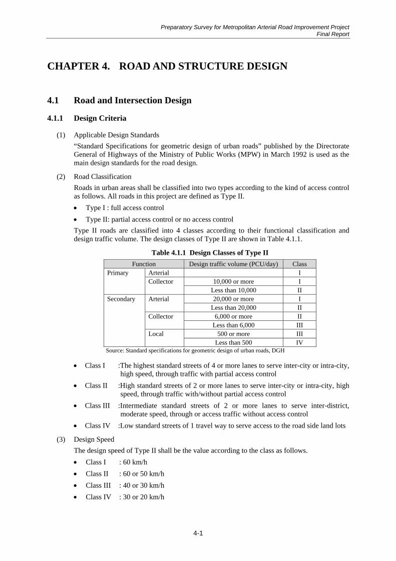

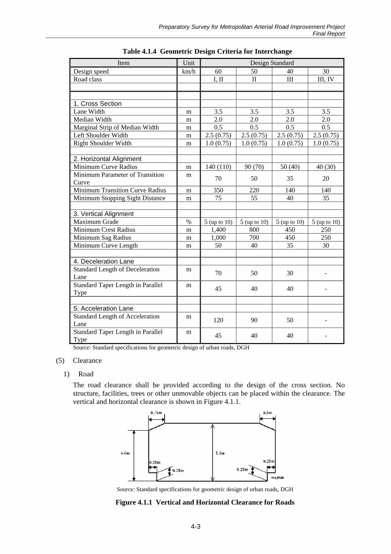


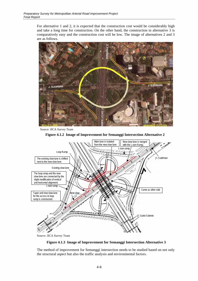
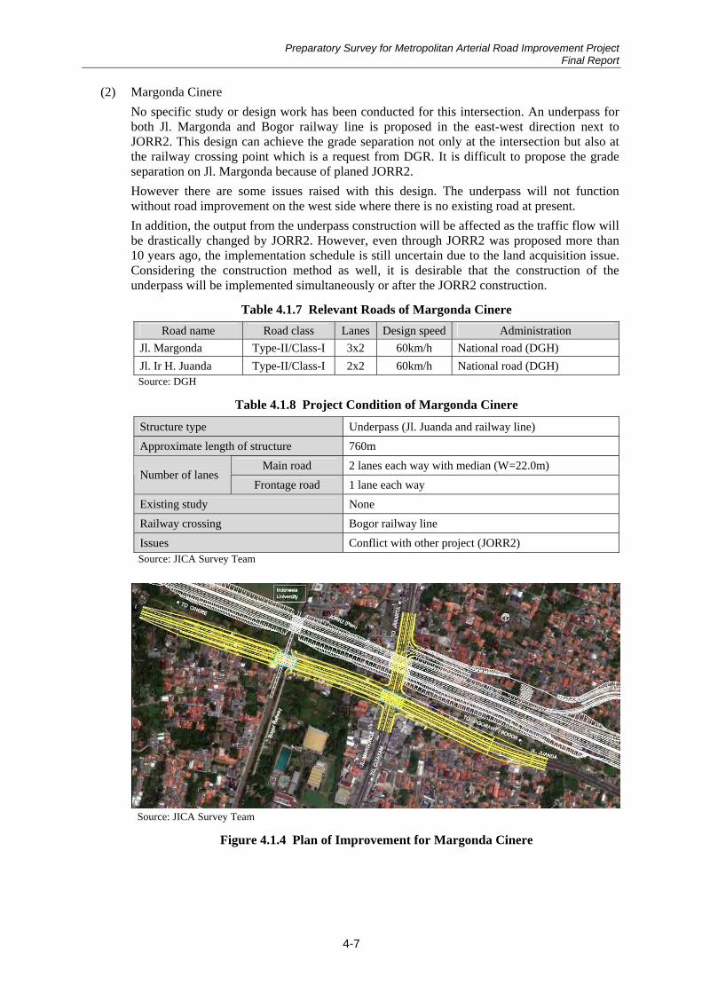
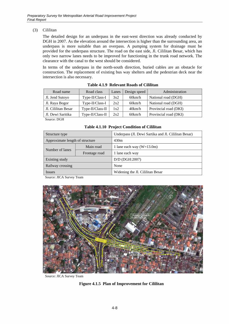


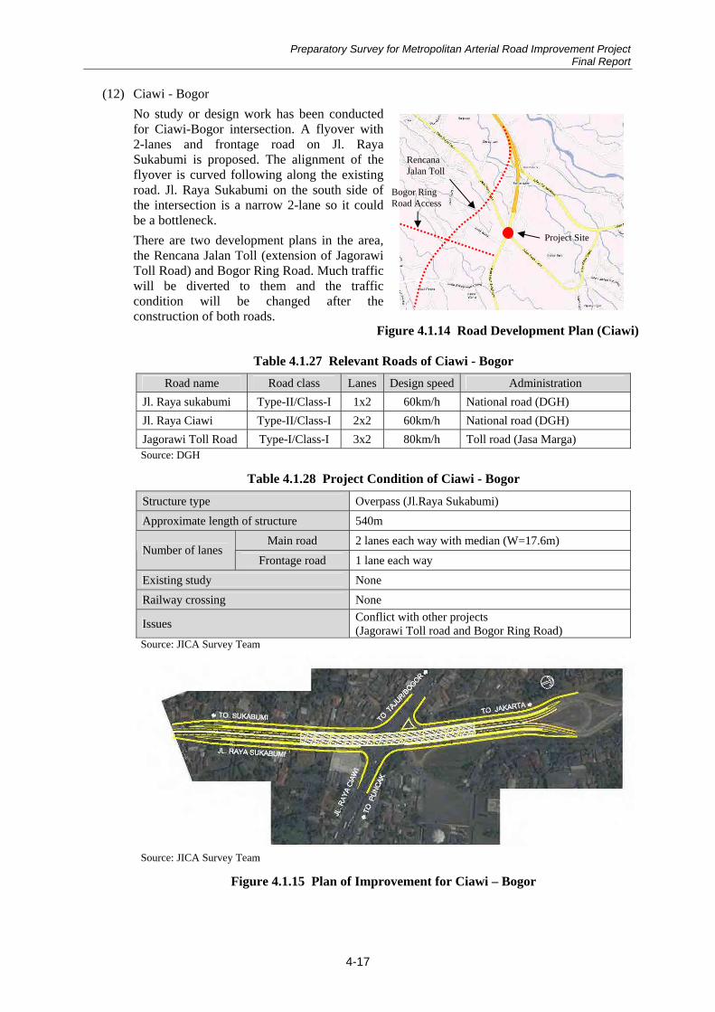


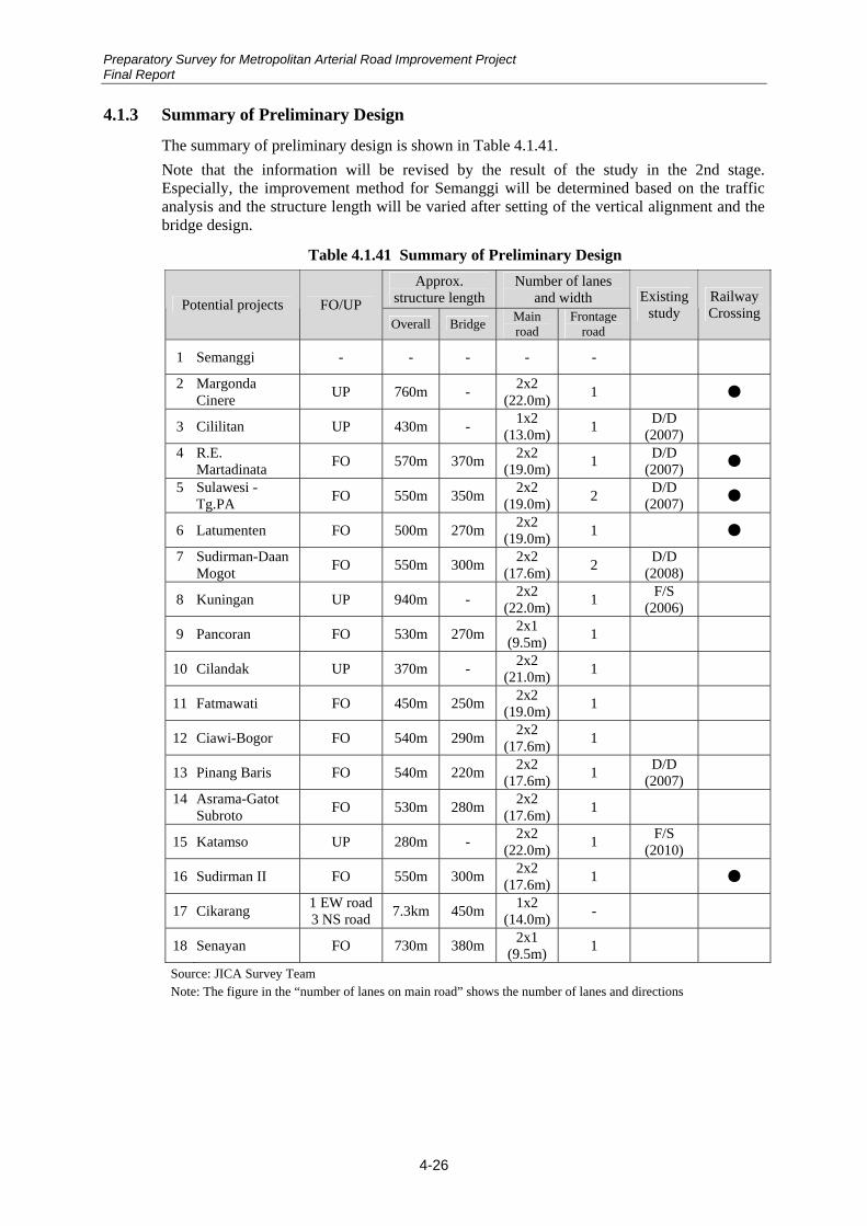
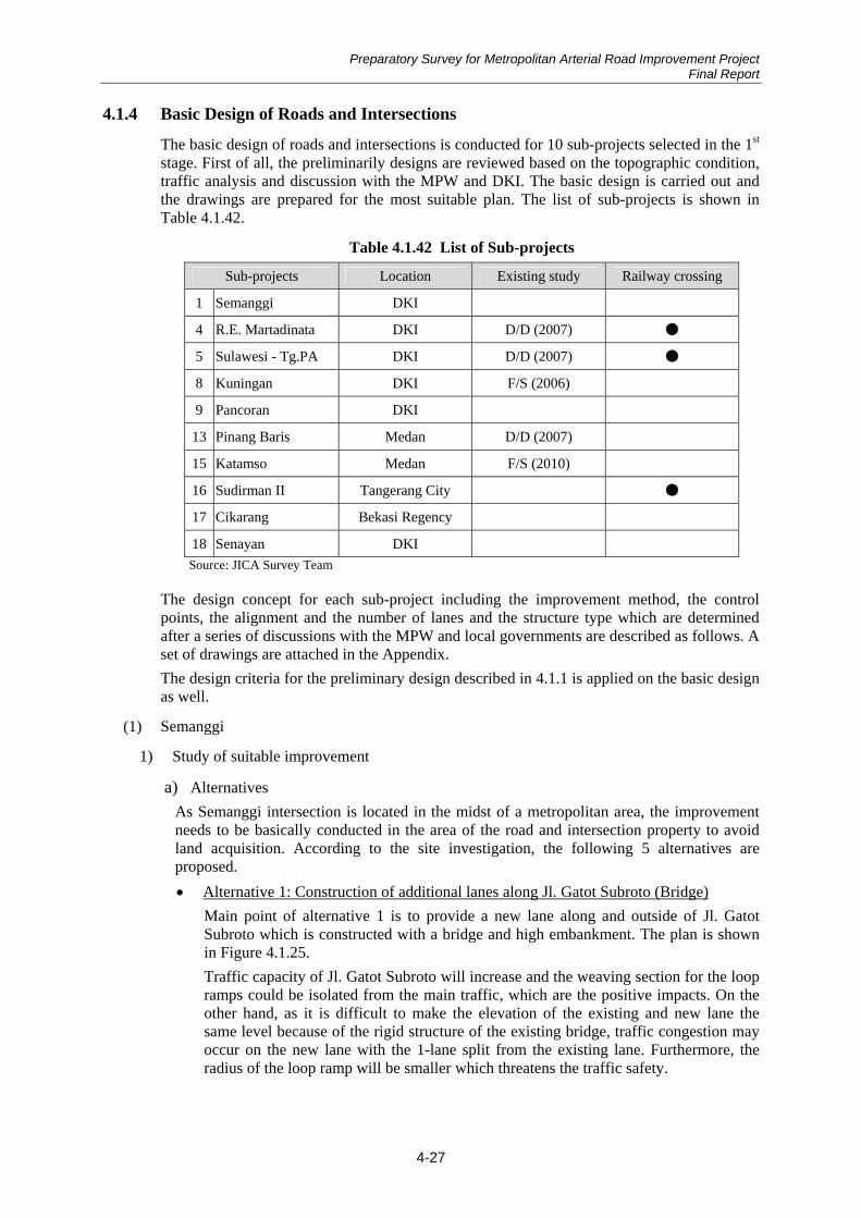
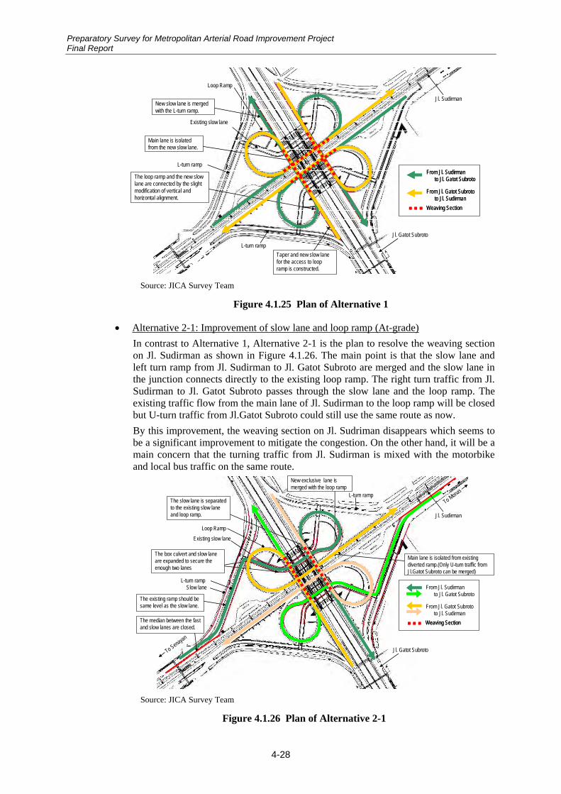

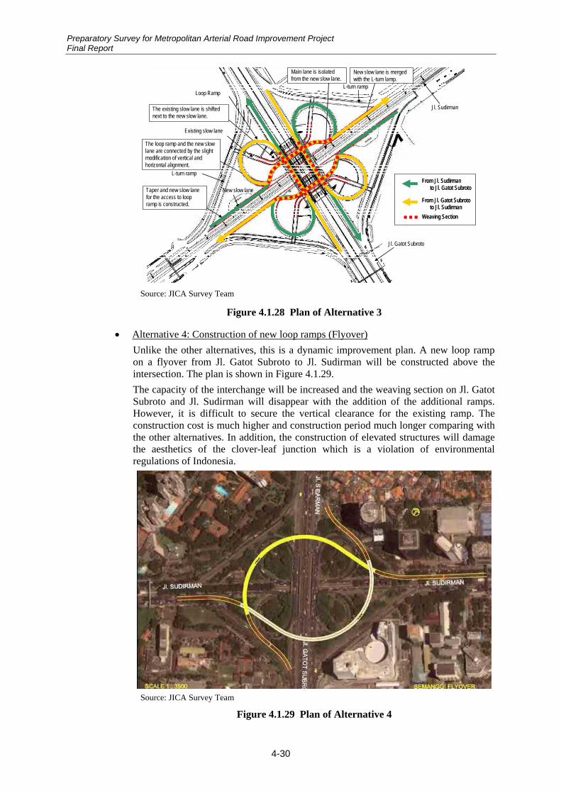


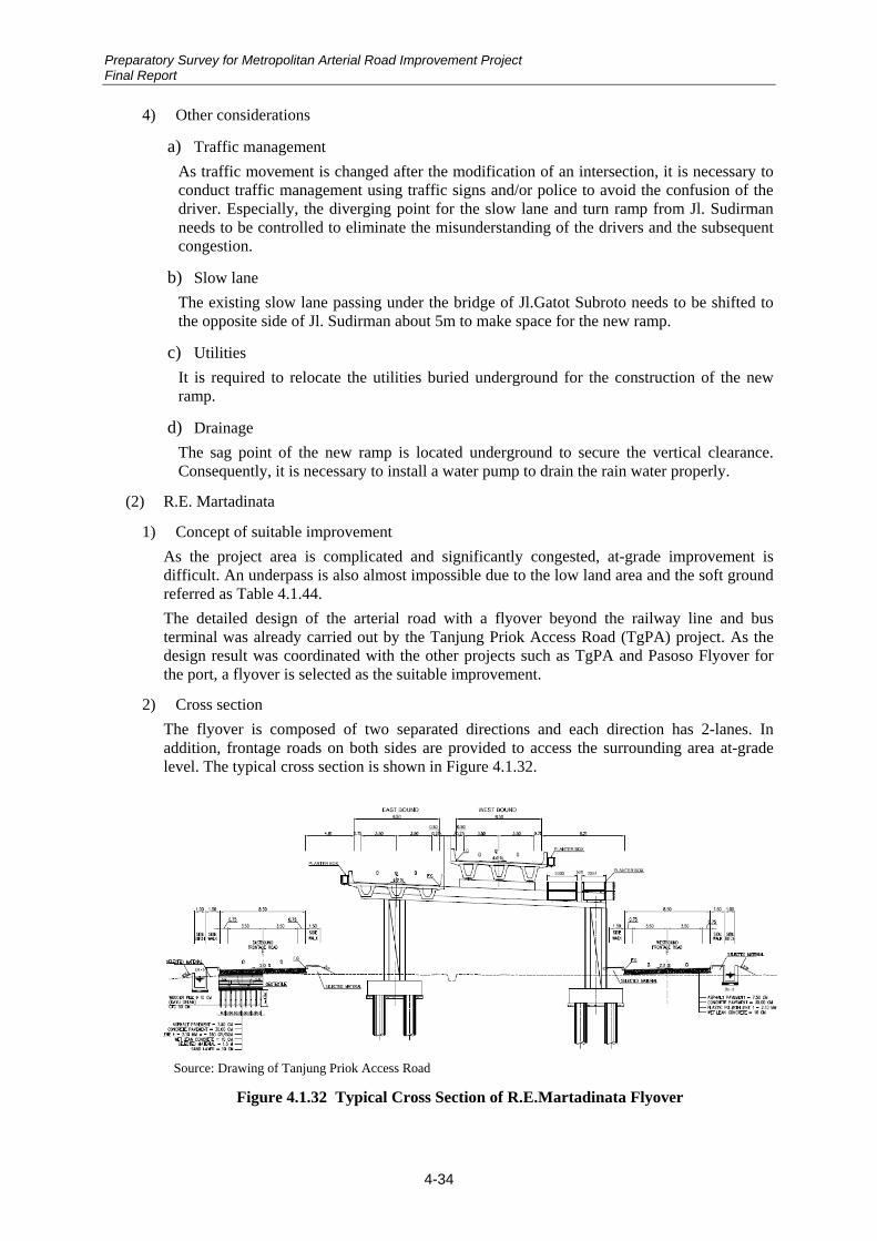


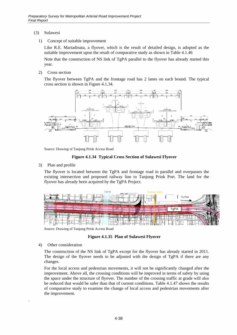


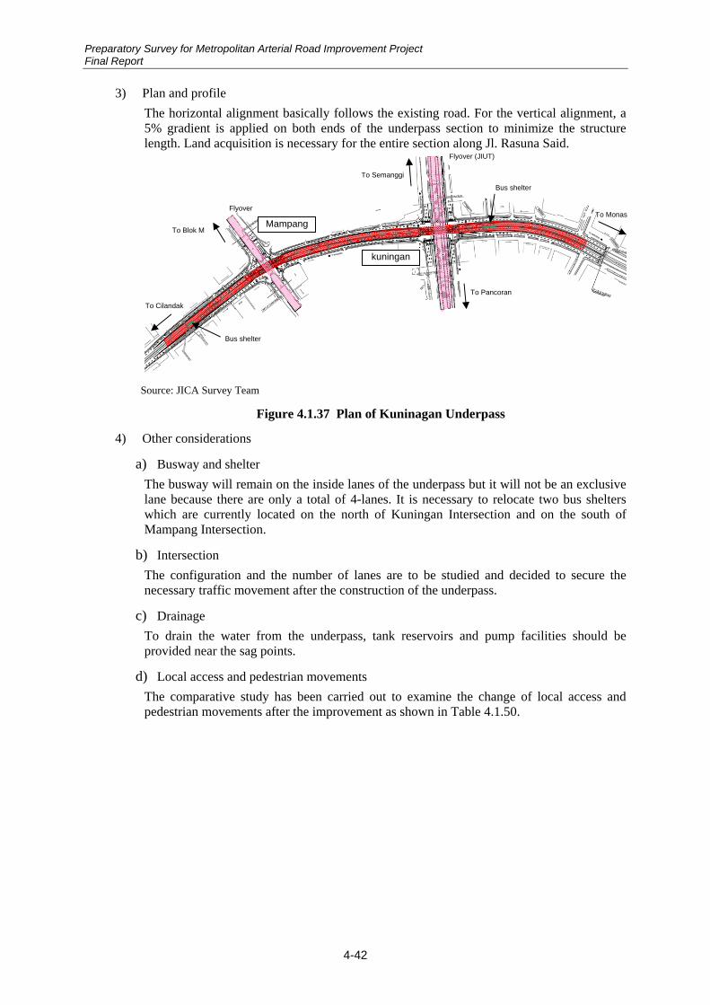


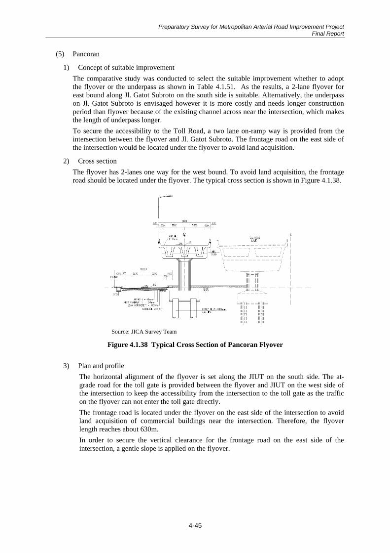


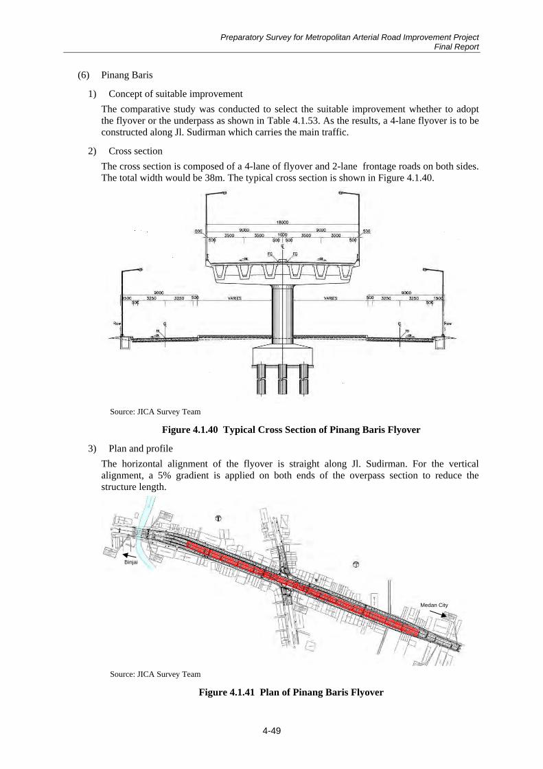

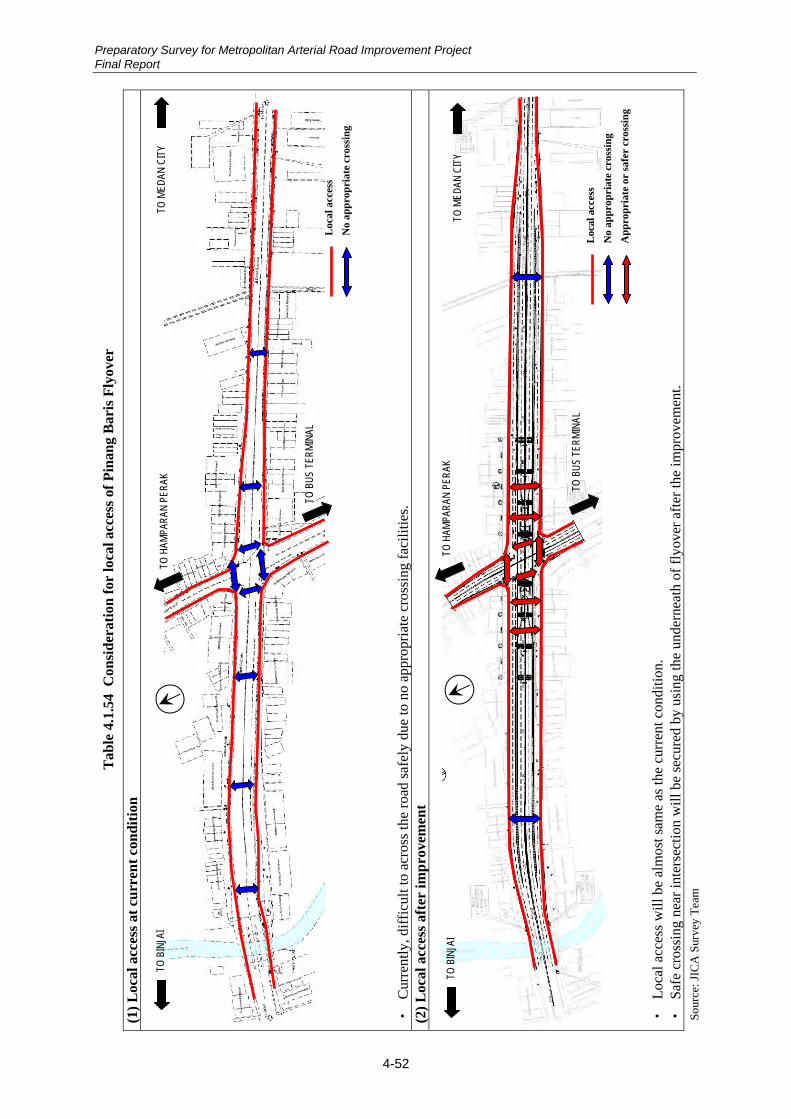
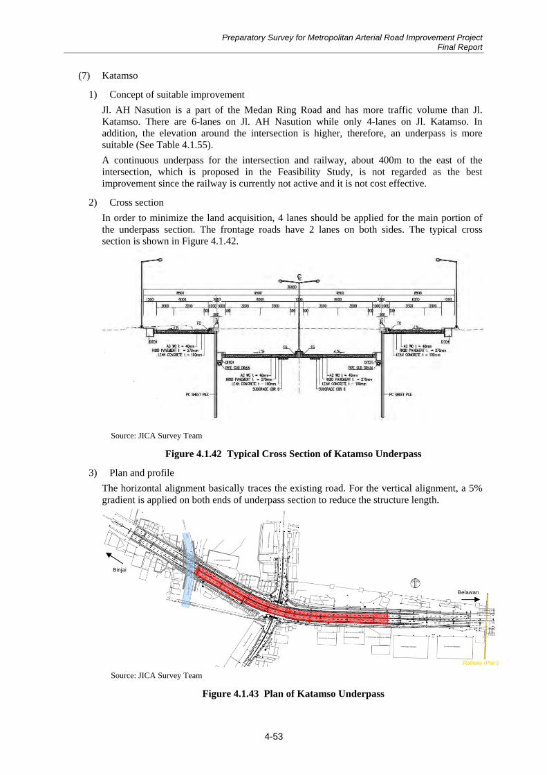


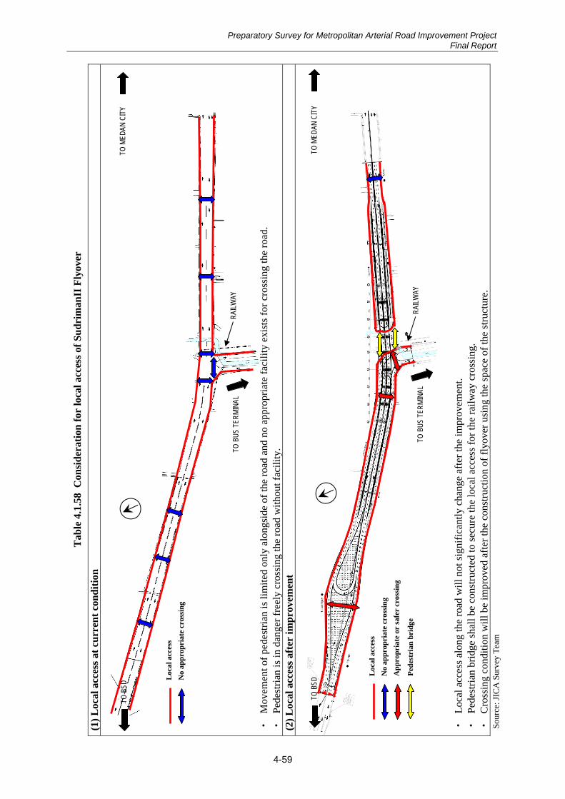


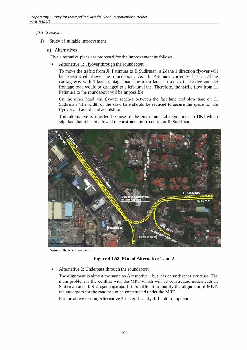


![LONDON CCLING DESIGN STANDARDS - Keeping · PDF fileLondon Cycling Design Standards [Chapter 1] Raising standards 02 1.1.4 Document structure ... of the busier main road cycle tracks](https://static.documents.pub/doc/80x56/5ab7a0037f8b9a684c8bba2b/london-ccling-design-standards-keeping-cycling-design-standards-chapter-1.jpg)