CHAPTER 41 FABRICATION OF OPTICS BY DIAMOND TURNING Richard L. Rhorer Los Alamos National Laboratory Los Alamos , New Mexico Chris J. Evans National Institute of Standards and Technology Gaithersburg , Maryland 41.1 GLOSSARY f feed rate (mm / rev) h peak-to-valley height R tip radius R a average absolute roughness 41.2 INTRODUCTION The use of special machine tools with single-crystal diamond-cutting tools to produce metal optics is called diamond turning. The manufacture of optical surfaces by diamond turning is relatively new compared to the traditional optical-polishing methods. In terms of geometry and motions required, the diamond-turning process is much like the step of ‘‘generating the optical surface’’ in traditional optical fabrication. However, the diamond- turning machine is a more sophisticated piece of equipment that produces the final surface, which typically does not need the traditional polishing operation. But surface quality produced by the ‘‘best’’ diamond turning does not yet match the best conventional- polishing practice. Yet, the limits of diamond turning for both figure and surface finish accuracy have not yet been reached. There are several important advantages of using diamond turning, including the ability to produce good optical surfaces to the edge of the element, to fabricate soft ductile materials dif ficult to polish, to eliminate alignment in some systems, and to fabricate shapes dif ficult to do by other methods. If the advantages of diamond turning suggest this fabrication method, then it is important to determine early in the design phase of a project whether the material specified is appropriate for diamond turning. 41.1
Transcript
CHAPTER 41 FABRICATION OF OPTICS BY DIAMOND TURNING
Richard L . Rhorer Los Alamos National Laboratory Los Alamos , New Mexico
Chris J . Evans National Institute of Standards and Technology Gaithersburg , Maryland
4 1 . 1 GLOSSARY
f feed rate (mm / rev)
h peak-to-valley height
R tip radius
R a average absolute roughness
4 1 . 2 INTRODUCTION
The use of special machine tools with single-crystal diamond-cutting tools to produce metal optics is called diamond turning . The manufacture of optical surfaces by diamond turning is relatively new compared to the traditional optical-polishing methods . In terms of geometry and motions required , the diamond-turning process is much like the step of ‘‘generating the optical surface’’ in traditional optical fabrication . However , the diamond- turning machine is a more sophisticated piece of equipment that produces the final surface , which typically does not need the traditional polishing operation . But surface quality produced by the ‘‘best’’ diamond turning does not yet match the best conventional- polishing practice . Yet , the limits of diamond turning for both figure and surface finish accuracy have not yet been reached .
There are several important advantages of using diamond turning , including the ability to produce good optical surfaces to the edge of the element , to fabricate soft ductile materials dif ficult to polish , to eliminate alignment in some systems , and to fabricate shapes dif ficult to do by other methods . If the advantages of diamond turning suggest this fabrication method , then it is important to determine early in the design phase of a project whether the material specified is appropriate for diamond turning .
41 .1
41 .2 OPTICAL FABRICATION
Sections in this chapter highlight the following :
$ The diamond-turning process $ The advantages of diamond turning $ Diamond-turnable materials $ Comparison of diamond turning and traditional optical fabrication $ Machine tools for diamond turning $ Basic steps in diamond turning $ Surface finish in diamond-turned optics $ Measuring diamond-turned surfaces $ Conclusions
4 1 . 3 THE DIAMOND - TURNING PROCESS
The diamond-turning process produces finished surfaces by very accurately cutting away a thin chip or layer of the surface . Thus , it is generally applicable to ductile materials that machine well rather than to hard brittle materials traditionally used for optical elements . (However , by using a grinding head on a diamond-turning machine in place of the tool , hard brittle materials can be finished . ) At very small ef fective depths of cut , brittle materials behave in an apparently ductile manner . This attribute allows fracture-free grinding of glasses and ceramics as well as diamond turning of optical surfaces on materials such as gemanium , zinc selenide , and potassium dihydrogen phosphate (KDP) .
In diamond turning , both the figure and surface finish are largely determined by the machine tool and the cutting process . Note , however , that materials characteristics such as grain size , inclusion size , etc . limit the ultimate surface finish achievable . The tool has to be very accurately moved with respect to the optical element to generate a good optical surface , and the edge of the diamond tool has to be extremely sharp and free of defects .
4 1 . 4 THE ADVANTAGES OF DIAMOND TURNING
The advantages of diamond turning over the more traditional optical fabrication technique of lapping and polishing (see Chap . 40 by R . E . Parks) are
$ It can produce good optical surfaces clear to the edge of the optical element . This is important , for example , in making scanners , polygons , special shaped flats , and when producing parts with interrupted cuts .
$ It can turn soft ductile materials that are extremely dif ficult to polish . $ It can easily produce of f-axis parabolas and other dif ficult-to-lap aspherical shapes . $ It can produce optical elements with a significant cost advantage over conventional
lapping and polishing where the relationship of the mounting surface—or other feature—to the optical surface are very critical . Expressed dif ferently , this feature of diamond turning of fers the opportunity to eliminate alignment in some systems .
$ The fabrication of some optical shapes , such as axicons and x-ray telescopes , would be extremely dif ficult by methods other than diamond turning .
Conflicts between optical requirements and diamond turnability on the one hand , and mechanical considerations on the other often lead to the use of platings . Plating
FABRICATION OF OPTICS BY DIAMOND TURNING 41 .3
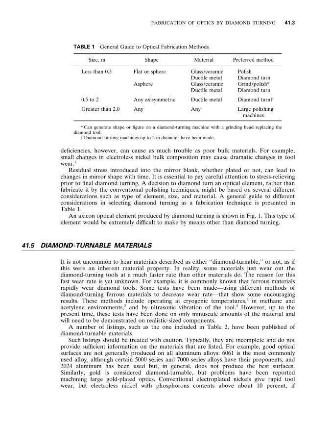
TABLE 1 General Guide to Optical Fabrication Methods
Size , m Shape Material Preferred method
Less than 0 . 5 Flat or sphere
Asphere
Glass / ceramic Ductile metal Glass / ceramic Ductile metal
Polish Diamond turn Grind / polish* Diamond turn
0 . 5 to 2 Any axisymmetric Ductile metal Diamond turn †
Greater than 2 . 0 Any Any Large polishing machines
* Can generate shape or figure on a diamond-turning machine with a grinding head replacing the diamond tool .
† Diamond-turning machines up to 2-m diameter have been made .
deficiencies , however , can cause as much trouble as poor bulk materials . For example , small changes in electroless nickel bulk composition may cause dramatic changes in tool wear . 1
Residual stress introduced into the mirror blank , whether plated or not , can lead to changes in mirror shape with time . It is essential to pay careful attention to stress-relieving prior to final diamond turning . A decision to diamond turn an optical element , rather than fabricate it by the conventional polishing techniques , might be based on several dif ferent considerations such as type of element , size , and material . A general guide to dif ferent considerations in selecting diamond turning as a fabrication technique is presented in Table 1 .
An axicon optical element produced by diamond turning is shown in Fig . 1 . This type of element would be extremely dif ficult to make by means other than diamond turning .
4 1 . 5 DIAMOND - TURNABLE MATERIALS
It is not uncommon to hear materials described as either ‘‘diamond-turnable , ’’ or not , as if this were an inherent material property . In reality , some materials just wear out the diamond-turning tools at a much faster rate than other materials do . The reason for this fast wear rate is yet unknown . For example , it is commonly known that ferrous materials rapidly wear diamond tools . Some tests have been made—using dif ferent methods of diamond-turning ferrous materials to decrease wear rate—that show some encouraging results . These methods include operating at cryogenic temperatures , 2 in methane and acetylene environments , 3 and by ultrasonic vibration of the tool . 4 However , up to the present time , these tests have been done on only minuscule amounts of the material and will need to be demonstrated on realistic-sized components .
A number of listings , such as the one included in Table 2 , have been published of diamond-turnable materials .
Such listings should be treated with caution . Typically , they are incomplete and do not provide suf ficient information on the materials that are listed . For example , good optical surfaces are not generally produced on all aluminum alloys : 6061 is the most commonly used alloy , although certain 5000 series and 7000 series alloys have their proponents , and 2024 aluminum has been used but , in general , does not produce the best surfaces . Similarly , gold is considered diamond-turnable , but problems have been reported machining large gold-plated optics . Conventional electroplated nickels give rapid tool wear , but electroless nickel with phosphorous contents above about 10 percent , if
41 .4 OPTICAL FABRICATION
FIGURE 1 An axicon optical element being diamond turned . ( Courtesy of Rank Taylor Hobson , Keene , New Hampshire . )
appropriately heat treated , can be machined ef fectively . 5 Recently , it has been shown that high-phosphorous electroplated nickel 6 , 7 also machines extremely well , although such platings are not widely available .
Silicon , although included in the listing given here , should be considered marginal as tool wear can be high . Reasonably large areas of amorphous silicon cladding are reported to have been successfully machined .
TABLE 2 Diamond-turnable Materials
Aluminum Brass Copper Beryllium copper Bronze Gold Silver Lead Platinum Tin Zinc Electroless nickel
Diamond turnability of plastics varies , with some suggestion that parameters , such as surface speed , are more important than for metal and crystalline substrates . Some plastics are , however , diamond turned in volume production .
Therefore , it is important to involve experienced personnel early in the design phase 8 to ensure that the material specified is appropriate . In some projects , the part is so valuable and / or so dif ficult to produce by other techniques , it is worth consuming tools more rapidly than would normally be acceptable . However , such a decision should be taken consciously , not by default late in a project .
4 1 . 6 COMPARISON OF DIAMOND TURNING AND TRADITIONAL OPTICAL FABRICATION
In diamond turning , the final shape and surface of the optical produced depends on the machine tool accuracy , whereas , in traditional optical fabrication , the final shape and surface of the optical element are produced by lapping and polishing with an abrasive- loaded lap . The dif ferences between diamond turning and traditional optical fabrication can be summarized by describing diamond turning as a displacement - controlled process versus a force - controlled process for traditional optical fabrication . 9 The goal in diamond turning is to have a machine tool that produces an extremely accurate path with the diamond tool , hence a displacement-controlled machine . A traditional polishing machine used for optical fabrication depends on the force being constant over the area where the abrasive-loaded lap—or tool—touches the surface being worked . Selective removal of material can be produced by increasing the lap pressure in selected areas or by use of a zone lap . The stif fness of a diamond-turning machine is important because , to control the displacement , it is important that cutting forces and other influences do not cause unwanted displacements . Feeds , speeds , and depth of cut are typically much lower in diamond turning than conventional machining , thus giving lower forces . However , the displacements of concern are also much lower . Thus the stif fness required is as much , or more , of a concern than conventional machining even though the total force capability may be lower for diamond turning .
4 1 . 7 MACHINE TOOLS FOR DIAMOND TURNING
In general , the machine tools used for diamond turning are very expensive compared to the equipment needed for traditional optical fabrication . The precision required for diamond turning is beyond the capability of conventional machine tools , thus some of the first diamond-turning machines for fabricating optics were built adapting Moore measuring machines . 1 0
Although there are some records of machine tools being used to generate optical surfaces as early as the 17th century , most of the ef fort is modern , accelerated in the 1960s and 1970s with the advent of computer-based machine tool controls and laser interferom- eter systems used as positional feedback devices . Evans 1 1 has documented much of the history of diamond turning and provides an extensive reference list . Some of the research in metal cutting related to diamond turning and associated machine tools is summarized by Ikawa . 1 2
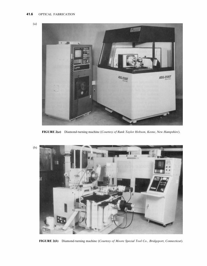
Two commercial diamond-turning machines are shown in Fig . 2 . Such machines may generally be configured to operate in a normal facing lathe mode (with the tool stationary and the part rotating) , as a milling machine (part stationary , tool rotating) , or , on occasion , as an optical generator—both part and tool rotating—with the addition of a second
41 .6 OPTICAL FABRICATION
FIGURE 2( a ) Diamond-turning machine ( Courtesy of Rank Taylor Hobson , Keene , New Hampshire ) .
(a)
FIGURE 2( b ) Diamond-turning machine ( Courtesy of Moore Special Tool Co . , Bridgeport , Connecticut ) .
(b)
FABRICATION OF OPTICS BY DIAMOND TURNING 41 .7
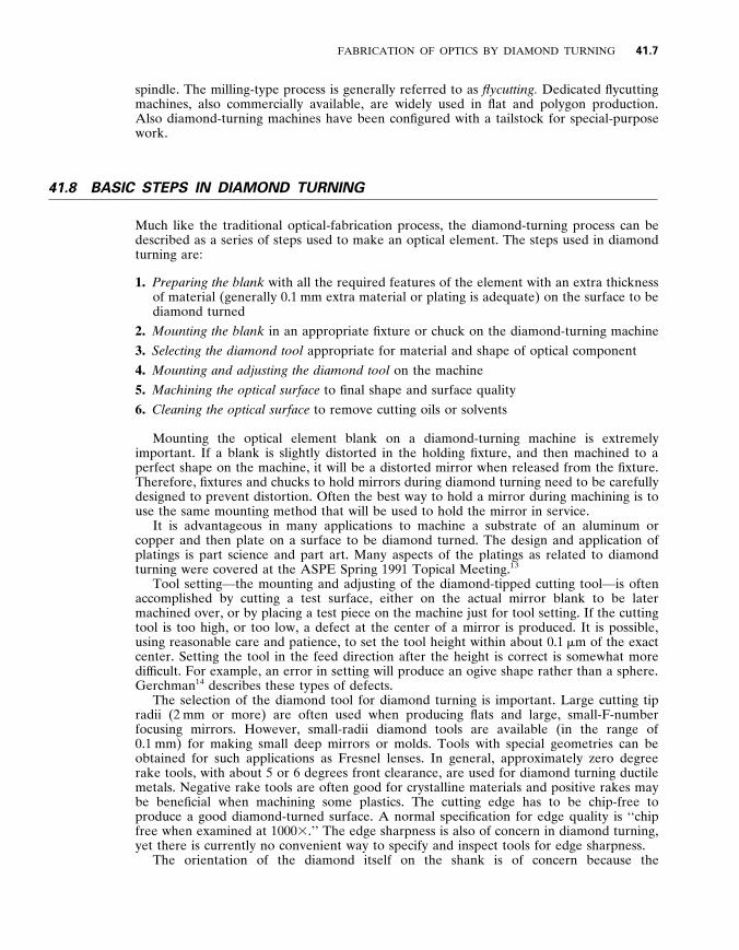
spindle . The milling-type process is generally referred to as flycutting . Dedicated flycutting machines , also commercially available , are widely used in flat and polygon production . Also diamond-turning machines have been configured with a tailstock for special-purpose work .
4 1 . 8 BASIC STEPS IN DIAMOND TURNING
Much like the traditional optical-fabrication process , the diamond-turning process can be described as a series of steps used to make an optical element . The steps used in diamond turning are :
1 . Preparing the blank with all the required features of the element with an extra thickness of material (generally 0 . 1 mm extra material or plating is adequate) on the surface to be diamond turned
2 . Mounting the blank in an appropriate fixture or chuck on the diamond-turning machine
3 . Selecting the diamond tool appropriate for material and shape of optical component
4 . Mounting and adjusting the diamond tool on the machine
5 . Machining the optical surface to final shape and surface quality
6 . Cleaning the optical surface to remove cutting oils or solvents
Mounting the optical element blank on a diamond-turning machine is extremely important . If a blank is slightly distorted in the holding fixture , and then machined to a perfect shape on the machine , it will be a distorted mirror when released from the fixture . Therefore , fixtures and chucks to hold mirrors during diamond turning need to be carefully designed to prevent distortion . Often the best way to hold a mirror during machining is to use the same mounting method that will be used to hold the mirror in service .
It is advantageous in many applications to machine a substrate of an aluminum or copper and then plate on a surface to be diamond turned . The design and application of platings is part science and part art . Many aspects of the platings as related to diamond turning were covered at the ASPE Spring 1991 Topical Meeting . 1 3
Tool setting—the mounting and adjusting of the diamond-tipped cutting tool—is often accomplished by cutting a test surface , either on the actual mirror blank to be later machined over , or by placing a test piece on the machine just for tool setting . If the cutting tool is too high , or too low , a defect at the center of a mirror is produced . It is possible , using reasonable care and patience , to set the tool height within about 0 . 1 m m of the exact center . Setting the tool in the feed direction after the height is correct is somewhat more dif ficult . For example , an error in setting will produce an ogive shape rather than a sphere . Gerchman 1 4 describes these types of defects .
The selection of the diamond tool for diamond turning is important . Large cutting tip radii (2 mm or more) are often used when producing flats and large , small-F-number focusing mirrors . However , small-radii diamond tools are available (in the range of 0 . 1 mm) for making small deep mirrors or molds . Tools with special geometries can be obtained for such applications as Fresnel lenses . In general , approximately zero degree rake tools , with about 5 or 6 degrees front clearance , are used for diamond turning ductile metals . Negative rake tools are often good for crystalline materials and positive rakes may be beneficial when machining some plastics . The cutting edge has to be chip-free to produce a good diamond-turned surface . A normal specification for edge quality is ‘‘chip free when examined at 1000 3 . ’’ The edge sharpness is also of concern in diamond turning , yet there is currently no convenient way to specify and inspect tools for edge sharpness .
The orientation of the diamond itself on the shank is of concern because the
41 .8 OPTICAL FABRICATION
single-crystal diamond is anisotropic . The orientation of diamond tools has been studied , for example , by Wilks , 1 5 Decker , 1 6 and Hurt . 1 7 It is necessary for the tool manufacturer to mount the diamond so that it can be shaped to the required radius and produce a good cutting edge . The usual orientation for diamond tools is with the cleavage plane horizontal—parallel to the rake face .
The actual diamond turning , or machining to final size and surface finish , is often the fastest part of the process . The machine-tool controller has to be programmed to pass the tool through the correct path , the chip-removal system has to be positioned , and the cutting-fluid applicator needs to be adjusted to provide consistent clean cutting .
For machining of flats and spherical surfaces , the computer machine control programs are straightforward . But when cutting aspherical surfaces , caution has to be exercised so that the radius of the tool is properly handled in calculating the tool path . Modern CAD systems perform the necessary calculations , but test cases should be done prior to cutting a dif ficult or expensive component .
In general , the cutting speeds for diamond turning are similar to those used for conventional machining : less than one to over 100 m / min . However , the slower cutting speeds produced by facing to the center of a workpiece do not af fect the surface finish in diamond turning as is often the case with nondiamond tools . Thus , varying the spindle speed to keep the cutting speed constant is not necessary in diamond turning . The upper speed for diamond turning is often limited by the distortion of the optical element due to centrifugal forces , expecially for larger elements . The upper spindle speed can also be limited due to any unbalance of the workpiece and fixture .
The feed rate in diamond turning is usually adjusted to give a good theoretical surface finish . (See the next section on the surface finish of diamond-turned optics . )
Cleaning of diamond-turned optics has a lot in common with cleaning conventionally polished optics . But because many of the diamond-turned elements are of soft metals , caution has to be exercised to prevent scratching . In general , a degreaser is used (soap or solvent) , followed by a rinse in pure ethyl alcohol . The drag-wiping technique traditionally used on some glass optics can be used on some diamond-turned elements . Care must be taken to insure that the lens tissue is very clean and remains wet . Some work is being done to study the best solvents to use for cleaning diamond-turned optics from an environmental-impact standpoint . 1 8
4 1 . 9 SURFACE FINISH IN DIAMOND - TURNED OPTICS
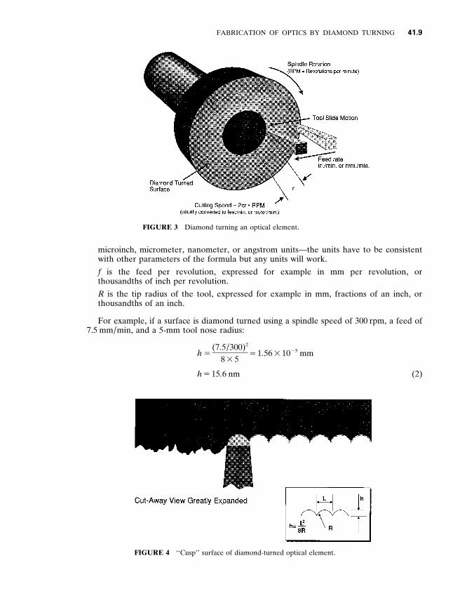
Surface structure is dif ferent for diamond-turned surfaces compared to conventionally polished surfaces . A diamond-turned surface is produced by moving a cutting tool across the surface of the turning component , as illustrated in Fig . 3 . Therefore , diamond-turned elements always have some periodic surface roughness , which can produce a dif fraction- grating ef fect , whereas polished optical surfaces have a random roughness pattern . The traditional ‘‘scratch and dig’’ approach to describing surfaces is not meaningful for diamond-turned surfaces .
The machining process produces a periodic surface structure directly related to the tool radius and feed rate . The theoretical diamond-turned surface is described in Fig . 4 . The formula displayed in the figure for calculating the height of the cusps is
h 5 f 2
8 R (1)
where ,
h is the peak-to-valley height of the periodic surface defect , usually expressed in
FABRICATION OF OPTICS BY DIAMOND TURNING 41 .9
FIGURE 3 Diamond turning an optical element .
microinch , micrometer , nanometer , or angstrom units—the units have to be consistent with other parameters of the formula but any units will work . f is the feed per revolution , expressed for example in mm per revolution , or thousandths of inch per revolution . R is the tip radius of the tool , expressed for example in mm , fractions of an inch , or thousandths of an inch .
For example , if a surface is diamond turned using a spindle speed of 300 rpm , a feed of 7 . 5 mm / min , and a 5-mm tool nose radius :
h 5 (7 . 5 / 300) 2
8 3 5 5 1 . 56 3 10 2 5 mm
h 5 15 . 6 nm (2)
FIGURE 4 ‘‘Cusp’’ surface of diamond-turned optical element .
41 .10 OPTICAL FABRICATION
In addition to the ‘‘theoretical finish’’ based on cusp structure , the measured surface finish on diamond-turned parts is influenced by other factors such as
$ Waviness within the long-wavelength cut-of f for surface measurement . This type of waviness may be correlated , for example , with slide straightness errors .
$ Asynchronous error motions . If , for a given angular spindle position , there is nonrepeatability in axial , radial , or tilt directions , these errors will transfer into surface structure . Details of spindle errors are important in diamond turning . Further informa- tion can be found in the Axis of Rotation Standard . 1 9
$ External and self-induced vibration , not at the spindle frequency nor at one of its harmonics , has the same ef fect on finish—measured across the lay—as asynchronous spindle motions .
$ Materials ef fects . Dif ferential elastic recovery of adjacent grains gives steps in the machined surface and an appearance commonly referred to as ‘‘orange peel . ’’ Impurities in the material can also degrade surface finish .
$ Within each cusp , there is repeated structure related to ‘‘roughness’’ of the edge of the tool .
4 1 . 1 0 MEASURING DIAMOND - TURNED SURFACES
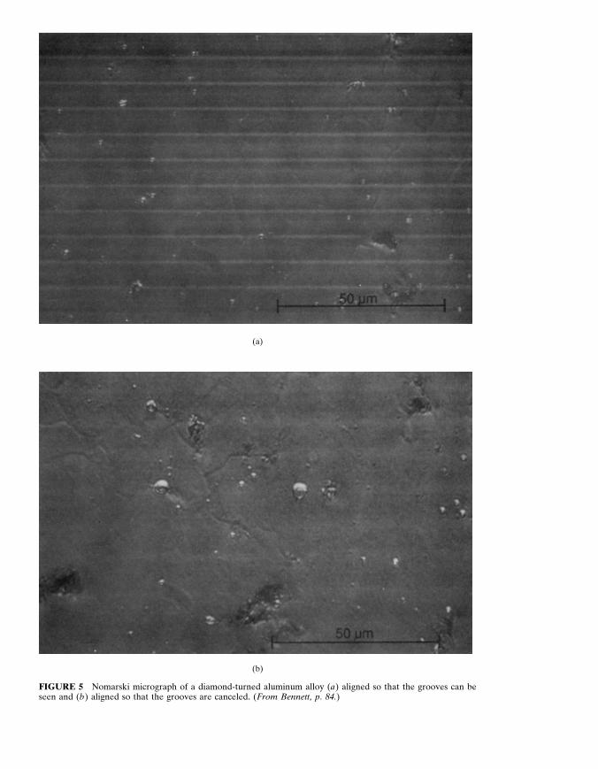
The measurement of diamond-turned surfaces presents some dif ficulties not encountered in conventional optics . In general , all methods used to measure optical surfaces are used on diamond-turned components . Bennett 2 0 presents a complete discussion of surface- roughness measurement . The Nomarski microscope is an excellent means of qualitatively evaluating diamond-turned surfaces . The Nomarski photos 2 1 in Fig . 5 illustrate the periodic machined structure of a diamond-turned surface . The feed rate used in producing the surface causes the periodic structure to be about 8 m m per revolution .
The measurement of the roughness of optical surfaces is performed by a number of dif ferent instruments , both stylus types and optical systems . If a surface is measured with an instrument that produces a profile , several dif ferent statistical methods can be used to describe the surface . Figure 6 illustrates a profile and some of the statistical parameters used in describing surfaces . The term peak-to-valley is often used in the diamond-turning shop to mean the dif ference between the highest and lowest points in any surface trace . The rms and Ra are also used to quantify a measured surface finish . These parameters are defined in Fig . 6 and as follows : 2 2
Although the rms roughness is generally used to describe the finish of optical surfaces , the a y erage roughness R a is normally used for roughness of machined surfaces . R a is simply the average of the absolute values of the surface height variations z i measured from the mean surface level (see Fig . 6) . Expressed in equation form , this is
R a 5 1 N O N
i 5 1 u z i u
If a surface has a profile that contains no large deviations from the mean surface level , the values of d and R a will be similar . However , if there are appreciable numbers of large ‘‘bumps’’ or ‘‘holes , ’’ the largest values of the z i ’s will dominate the surface statistics and d will be larger than R a .
(a)
(b)
FIGURE 5 Nomarski micrograph of a diamond-turned aluminum alloy ( a ) aligned so that the grooves can be seen and ( b ) aligned so that the grooves are canceled . ( From Bennett , p . 8 4 . )
41 .12 OPTICAL FABRICATION
FIGURE 6 Schematic representation of a rough surface showing statistical parameters . ( From Bennett , p . 3 9 . )
4 1 . 1 1 CONCLUSIONS
Diamond turning has been used for many years to commercially produce infrared optics . Some visible and ultraviolet applications are now possible . Moreover , the limits of diamond turning for both figure and surface finish accuracy have not yet been reached . Taniguchi 2 3 and others have shown that precision in both conventional machining and ultraprecision machining , such as diamond turning , has steadily improved for many decades , with roughly a factor of three improvement-in-tolerances possible every ten years . If this trend continues , we could expect diamond-turning machines with accuracies below 10 nm by the year 2000 . Yet , it is important to remember that it becomes increasingly dif ficult to push the capabilities in this regime . Research in the field of nanofabrication— working with dimensions on the order of molecules , or tenths of nm—may help extend diamond turning into the nanometer range .
The technology developed for diamond-turning optics in some industries is now beginning to impact the precision machining of nonoptical components . In the future , the improvement of all machine tools will likely be driven by both optical and nonoptical applications , with diamond-turning machines possibly reaching the accuracy level that will allow visible and ultraviolet optics to be fabricated by machining or grinding without postpolishing .
4 1 . 1 2 REFERENCES
1 . C . K . Syn , J . S . Taylor , and R . R . Donaldson , ‘‘Diamond Tool Wear vs . Cutting Distance , ’’ Proc . SPIE 656 .
4 . T . Moriwaki , ‘‘Ultraprecision Diamond Turning of Stainless Steel by Applying Ultrasonic Vibration , ’’ CIRP Annals 40 : 559 – 562 (1991) .
5 . J . S . Taylor , C . K . Syn , T . T . Saito , and R . R . Donaldson , ‘‘Surface Finish Measurements of Diamond Turned Electroless Nickel Plated Mirrors , ’’ Optical Engineering 25 (9) : 1013 – 1020 (Sept 1986) .
6 . A . Mayer , et al ., ‘‘Electrodeposited Coatings for Diamond Turning Applications , ’’ Proceedings ASPE Spring Topical Meeting , ‘‘Metal Platings for Precision Finishing Operations , ’’ 1991 .
7 . C . J . Evans , R . S ., Polvani , and A . Mayer , ‘‘Diamond Turned Electrodeposited Nickel Alloys , ’’ OSA Technical Digest Series 9 : 110 (1990) .
8 . J . S . Taylor and C . J . Evans , ‘‘Fabrication of a Metal Plated Mirror , Beginning from a Performance Specification , ’’ Proceedings ASPE Spring Topical Meeting , ‘‘Metal Platings for Precision Finishing Operations , ’’ 1991 .
9 . A . Gee , Cranfield Institute of Technology , in a private communication to the authors used the description of ‘‘displacement’’ controlled and ‘‘force’’ controlled .
10 . W . R . Moore , Foundations of Mechanical Accuracy , Moore Special Tool Co ., Bridgeport , Conn ., 1970 .
11 . C . J . Evans , Precision Engineering : An E y olutionary View , Cranfield Press , Bedford , UK , 1989 , pp . 135 – 155 .
12 . N . Ikawa , et al ., ‘‘Ultraprecision Metal Cutting : the Past , the Present , and the Future , ’’ CIRP Annals 40 : 587 – 594 (1991) .
13 . ASPE , ‘‘Metal Platings for Precision Finishing Operations , ’’ Spring Topical Meeting , Raleigh , N . C ., 1991 .
14 . M . C . Gerchman , ‘‘Optical Tolerancing for Diamond Turning Ogive Error , ’’ Proc . SPIE (Reflective Optics II) : 224 – 229 (1989) .
15 . J . Wilks , ‘‘Performance of Diamonds as Cutting Tools for Precision Machining , ’’ Precision Engineering 2 : 57 – 71 (1980) .
16 . D . C . Decker , H . H . Hurt , J . H . Dancy , and C . W . Fountain , ‘‘Preselection of Diamond Single Point Tools , ’’ Proc . SPIE 508 (1986) .
17 . H . H . Hurt and D . L . Decker , ‘‘Tribological Considerations of the Diamond Single Point Tool , ’’ Proc . SPIE 508 (1986) .
18 . L . A . Theye and R . D . Day , ‘‘Evaluation of Environmentally Safe Cleaning Agents for Diamond Turned Optics , ’’ ASPE Proceedings , ASPE , Raleigh , N . C ., 1991 .
19 . ANSI / ASME B89 . 3 . 4M-1985 Standard : ‘‘Axes of Rotation , Methods for Specifying and Testing , ’’ ASME , New York , 1985 .
20 . J . M . Bennett and L . Mattsson , Introduction to Surface Roughness and Scattering , Optical Society of America , Washington , D . C ., 1989 .