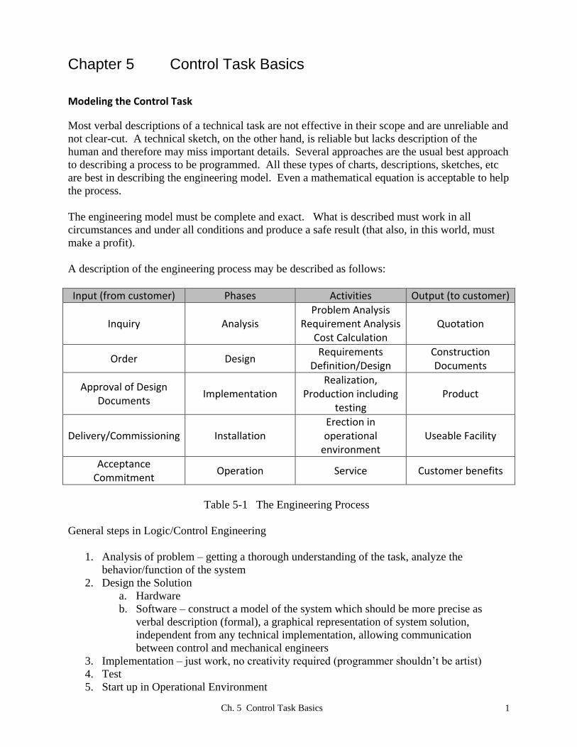
Ch. 5 Control Task Basics 1 Chapter 5 Control Task Basics Modeling the Control Task Most verbal descriptions of a technical task are not effective in their scope and are unreliable and not clear-cut. A technical sketch, on the other hand, is reliable but lacks description of the human and therefore may miss important details. Several approaches are the usual best approach to describing a process to be programmed. All these types of charts, descriptions, sketches, etc are best in describing the engineering model. Even a mathematical equation is acceptable to help the process. The engineering model must be complete and exact. What is described must work in all circumstances and under all conditions and produce a safe result (that also, in this world, must make a profit). A description of the engineering process may be described as follows: Input (from customer) Phases Activities Output (to customer) Inquiry Analysis Problem Analysis Requirement Analysis Cost Calculation Quotation Order Design Requirements Definition/Design Construction Documents Approval of Design Documents Implementation Realization, Production including testing Product Delivery/Commissioning Installation Erection in operational environment Useable Facility Acceptance Commitment Operation Service Customer benefits Table 5-1 The Engineering Process General steps in Logic/Control Engineering 1. Analysis of problem – getting a thorough understanding of the task, analyze the behavior/function of the system 2. Design the Solution a. Hardware b. Software – construct a model of the system which should be more precise as verbal description (formal), a graphical representation of system solution, independent from any technical implementation, allowing communication between control and mechanical engineers 3. Implementation – just work, no creativity required (programmer shouldn’t be artist) 4. Test 5. Start up in Operational Environment
Transcript
Ch. 5 Control Task Basics 1
Chapter 5 Control Task Basics
Modeling the Control Task
Most verbal descriptions of a technical task are not effective in their scope and are unreliable and
not clear-cut. A technical sketch, on the other hand, is reliable but lacks description of the
human and therefore may miss important details. Several approaches are the usual best approach
to describing a process to be programmed. All these types of charts, descriptions, sketches, etc
are best in describing the engineering model. Even a mathematical equation is acceptable to help
the process.
The engineering model must be complete and exact. What is described must work in all
circumstances and under all conditions and produce a safe result (that also, in this world, must
make a profit).
A description of the engineering process may be described as follows:
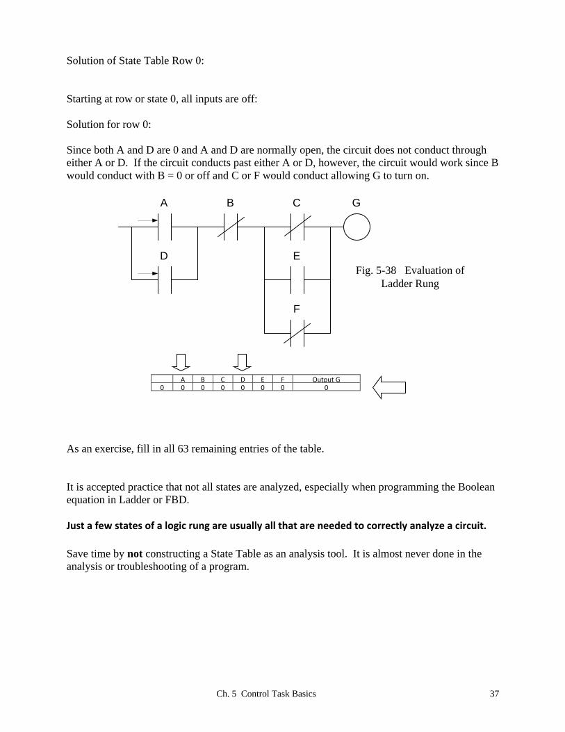
Since both A and D are 0 and A and D are normally open, the circuit does not conduct through
either A or D. If the circuit conducts past either A or D, however, the circuit would work since B
would conduct with B = 0 or off and C or F would conduct allowing G to turn on.
Fig. 5-38 Evaluation of
Ladder Rung
B
E
A C G
D
F
A B C D E F Output G
0 0 0 0 0 0 0 0
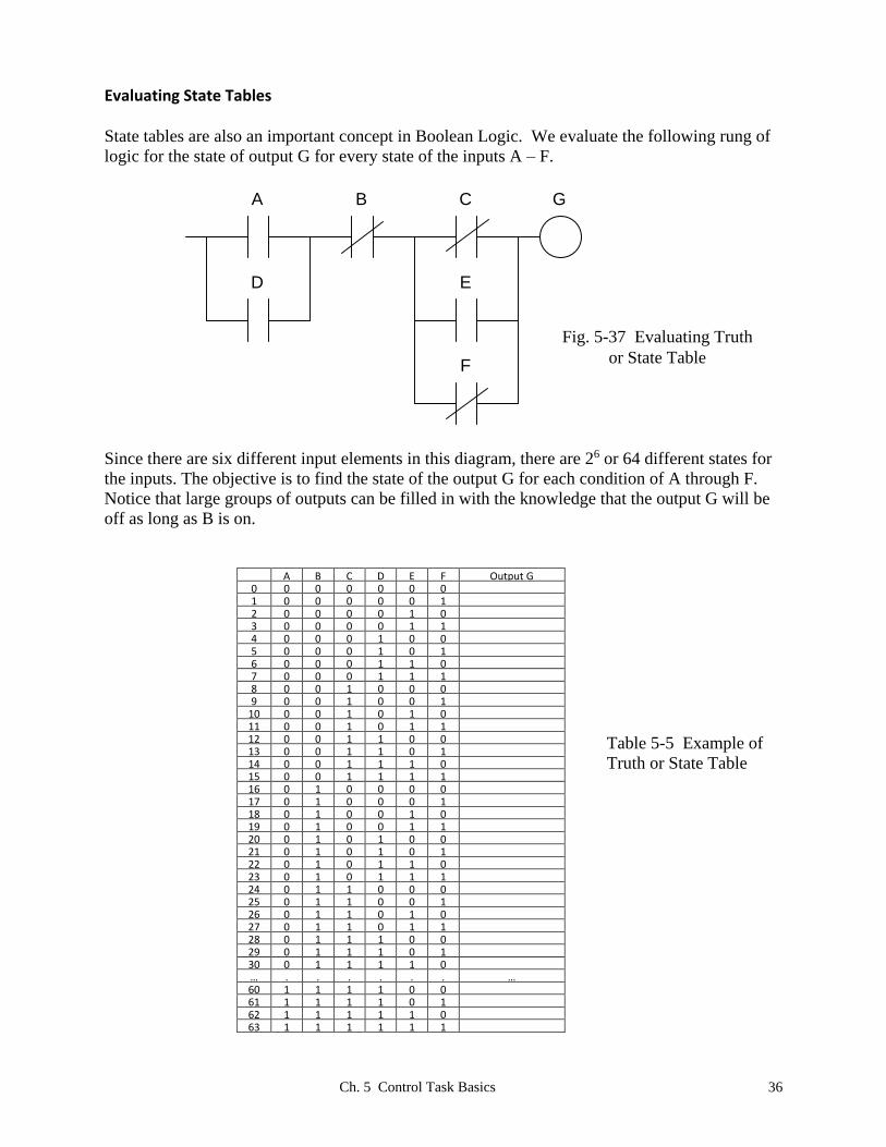
As an exercise, fill in all 63 remaining entries of the table.
It is accepted practice that not all states are analyzed, especially when programming the Boolean
equation in Ladder or FBD.
Just a few states of a logic rung are usually all that are needed to correctly analyze a circuit. Save time by not constructing a State Table as an analysis tool. It is almost never done in the
analysis or troubleshooting of a program.
Ch. 5 Control Task Basics 38
A Common Programming Error
Early programming efforts may lead to the following error: While all errors cannot possibly be
predicted, this one is a common error in many students’ early programming efforts. RSLogix
500 is used as the programming language.
Fig. 5-39 Double Use of Coils
First the programmer enters the first rung to turn on the coil O:0/0. Then later the second rung is
also entered to turn on the same output O:0/0. This does not work! The scanning nature of the
program will turn on the first output as set by the conditions of rung 0. Then rung 1 is solved
and the same output is written over with conditions set by rung 1.
The general rule is: Last coil wins!
Fig. 5-40 Solution of Double Coil Problem
The combination of the two rungs into one is required to allow both earlier rungs to work
properly. The concept of double-use of a coil will be discussed later and exceptions will appear
that allow its use. However, be careful! The concept of not double-using a coil is important in
all PLC programming including Allen-Bradley as well as Siemens.
Ch. 5 Control Task Basics 39
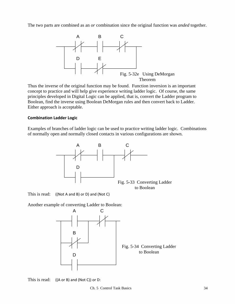
An Example of Combination Logic
An example problem will help with development of combinational logic. There are no memory
circuits necessary in the problem. Design logic to control the process:
Problem Statement:
A car wash with two bays has a pump supplying water pressure to the spray heads. If both bays
are in use or if one bay requires a second set of heads for a tall truck, a second pump is required.
The Tall truck request is made via a selector switch for each bay. If both bays are in use with a
tall truck in one or both bays, a third pump is required.
Bay 1 Bay 2
Bay 1
in use
Bay 2
in use
Tall
_Truck
Y N
Primary Pump
Second Pump
Tall
_Truck
Y N
xo xoThird Pump
Fig. 5-41 Car Wash
First to be completed are the definition tables:
Definition of Inputs: Table 5-6a
Sensor Function/State Signal Assignment
contact Bay 1 in use 1 (NO)
contact Bay 2 in use 1 (NO)
selector switch Tall Truck in Bay 1 1 (NO)
selector switch Tall Truck in Bay 2 1 (NO)
Ch. 5 Control Task Basics 40
Definition of Outputs: Table 5-6b
Actuator Function/State Signal Assignment
motor starter run pump 1 1
motor starter run pump 2 1
motor starter run pump 3 1
Write Boolean equations for the above:
(left as exercise)
Convert the Boolean equations to Ladder Logic:
First, picture the logic from what needs to be accomplished:
run pump 1
run pump 2
run pump 3
Then begin to formulate what is necessary to turn on each pump. If you can say the function,
then writing it is easy.
Say “to run pump 1, either bay 1 is in use or bay 2 is in use”. If you agree that this is what is
necessary to run the first pump, then picture the function in boolean or ladder:
(Bay 1 in use) + (Bay 2 in use) = run pump 1
Here “+” is read “or”. Next convert the Boolean statement to ladder logic as the following:
Ch. 5 Control Task Basics 41
run pump 1Bay 1 in use
Bay 2 in use
Then, concentrate on pump 2 and describe all conditions necessary to turn on this pump. Go
back to the original problem statement to draw from:
“If both bays are in use or if one bay requires a second set of heads for a tall truck, a second
pump is required.”
Describe this statement in boolean and ladder:
((Bay 1 in use) * (Bay 2 in use)) + (Bay 1 in use)*(Tall truck in bay 1)+ (Bay 2 in use)*(Tall truck in bay 2) = run pump 2
run pump 2Bay 1 in use Bay 2 in use
Bay 1 in use
Bay 2 in use
Tall Trk Bay 1
Tall Trk Bay 2
The third pump will be left as an exercise. Each input must be properly identified and addressed
as either an input from the wired input list or from the logic developed in the program. A-B and
Siemens require the addressing follow their convention for this. Internal logic may use names
that are may be the same as the other since a tag may be used with the user’s designation.
Programs may look very similar with internal logic used since the tags may be the same. It is up
to the programmer to choose names that are descriptive for the eventual user to be able to
understand quickly the logic.
Ch. 5 Control Task Basics 42
Summary
This chapter begins the programming process. First, the decision as to an I/O list must be
defined. Then various statements are made that define the logic. If Boolean logic is used in the
process, the result is a program that eventually is translated to Ladder or FBD to incorporate into
the program. Addresses are assigned to the inputs, outputs and internal logic. If bit logic is used,
the tags are assigned “bool” as the type. Other types are discussed in later chapters.
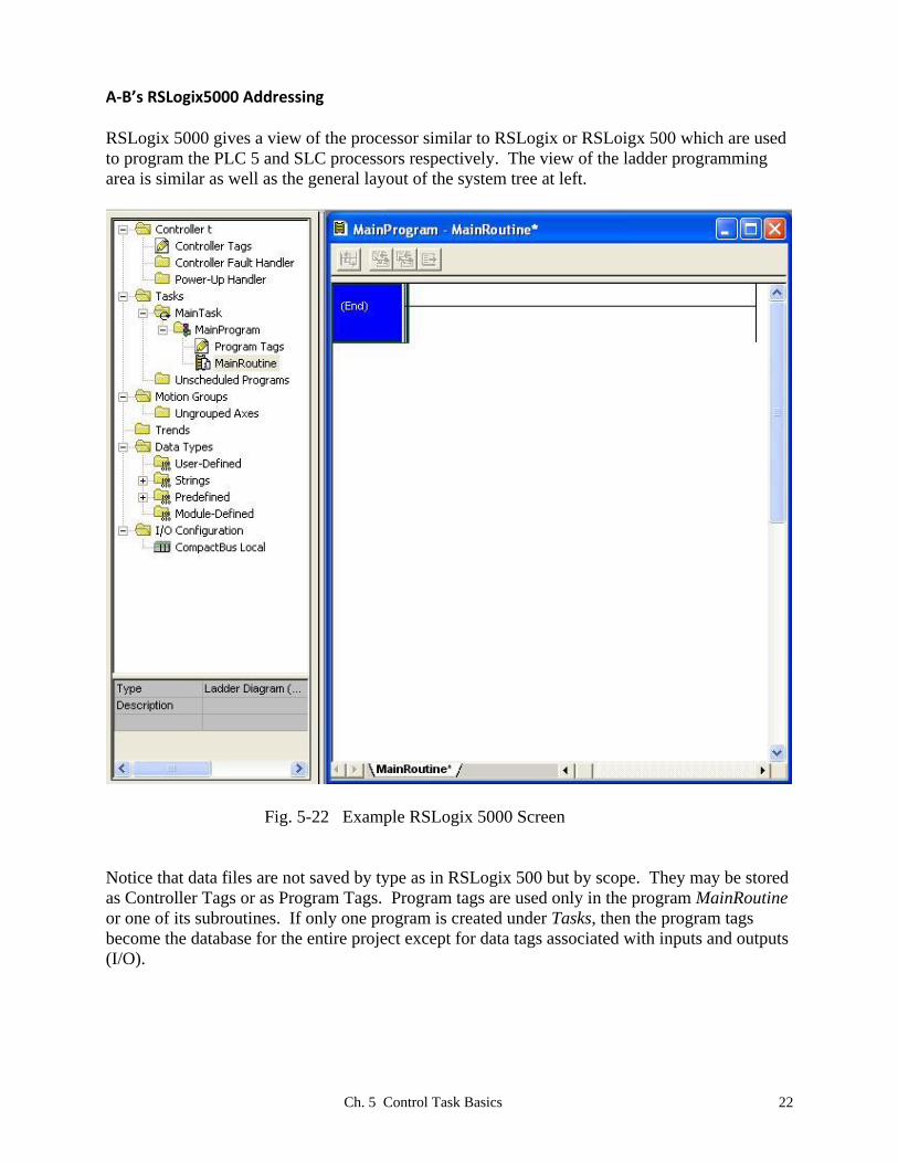
The addressing of Siemens S7-1200, A-B SLC (RSLogix 500) and A-B Compact (RSLogix
5000) are discussed. The two that are used in the labs are S7-1200 and A-B Compact. The older
SLC architecture is used as a reference for those who may still need to maintain this system.
Logic statements are designed in ladder and analyzed. The analysis includes DeMorgan
negation. This method is used primarily to familiarize the student with ladder statements and
require the student to analyze the ladder statement in a logical manner. The student may first
convert the ladder to Boolean, negate the Boolean and then convert back or they may opt to
convert the ladder directly. Either approach is accepted.
Other examples show the conversion from Boolean to ladder and from ladder to Boolean. Truth
tables are also introduced but not encouraged. All these examples are designed to show the
student similarities between the Ladder (and FBD) logic developed in the PLC and the logic
from the student’s digital experiences.
This chapter began with an example of a juice maker. While the logic can be developed in this
chapter, it will emerge that the logic for the juice maker requires additional understanding of
memory circuits to complete the logic for this problem. That logic awaits the student in the next
chapter.
Ch. 5 Control Task Basics 43
Exercises
1. *A car wash with two bays has a pump supplying water pressure to the spray heads. If both
bays are in use or if one bay requires a second set of heads for a tall truck, a second pump is
required. The Tall truck request is made via a selector switch for each bay. If both bays are
in use with a tall truck in one or both bays, a third pump is required.
Bay 1 Bay 2
Bay 1
in use
Bay 2
in use
Tall
_Truck
Y N
Primary Pump
Second Pump
Tall
_Truck
Y N
xo xoThird Pump
Fig. 5-41 Car Wash
Definition of Inputs: Table 5-6a
Sensor Function/State Signal Assignment
Definition of Outputs: Table 5-6b
Actuator Function/State Signal Assignment
Ch. 5 Control Task Basics 44
Write Boolean equations for the above:
Convert the Boolean equations to Ladder Logic:
2. *A design change was noticed by the engineer who saw that the xo on the selector switch for
Bay 2’s Tall Truck Selector switch was really wired ox. Would this change affect the Input
Signal Assignment, Boolean equations, or ladder logic? If so, how?
3. Which pump of problem #1 will be on the most? Is this a good design? Describe how you
would change the design if you do not agree that this is a good design.
4. Develop a logic statement in Boolean, FBD and Ladder to turn on an output when switch X
and switch Y are energized or when switch Z is energized:
5. Develop a logic statement in Boolean, FBD and Ladder to turn on an output when switch U is
on or when only one of the two following is on: V energized, W energized.
6. Develop a logic statement in Boolean, FBD and Ladder to energize the engine start circuit
when the key is in the ignition, all (3) front-passenger seat belts are engaged (in which a
person is sitting), and all doors are closed (assume a 4-door car).
7. *Use the following ladder rung to answer the following three questions:
B
E
A
C D
F
Fig. 5-42
a. Write the DeMorgan of the circuit above using ladder format.
b. Write the Boolean equivalent of the circuit above.
c. Create a truth table and find the state of F for each condition of A-E.
Ch. 5 Control Task Basics 45
8. *Use the following ladder rung to answer questions a and b of #7, above:
B
E
A
C D
F
Fig. 5-43
9. *Use the following ladder rung to answer questions a and b of #7, above:
B
EA
C
D F
Fig. 5-44
10. *Use the following ladder rung to answer questions a and b of #7 above:
B
E
A C G
D
F
Fig. 5-45
Write as ladder logic the following Boolean expressions:
11. (a and not b and not c) equal output d
12. (a or not b) and (c or not d or not e) equal output f
Ch. 5 Control Task Basics 46
13. *(a or not b or not c or not d) and (not e or not f) and (not g or h) equal output j
14. (a or b) and c equal output d
15. Convert the following Allen-Bradley’s RSLogix 500’s B3: addresses from word/bit format to
bit format:
a. B3:0/2 b. B3:2/5 c. B3:10/9 d. B3:6/15
16. Convert the following B: addresses from bit format to word/bit format:
a. B3/20 b. B3/8 c. B3/56 d. B3/211
17. *The attached buttons and coin slot sensors are part of an arcade game. Two games are in
the same arcade box. One is a cheap game and one is a good game. If the player inserts
quarters in any three of the four slots marked quarter 1 through quarter 4, and pushes the
Request Cheap button, the cheap game starts. If the player puts quarters in all four of the
quarter slots and pushes the Request Good button, the good game starts. Program rungs to
energize a coil for starting the cheap game and a coil for starting the good game. The cheap
game does not start if all four quarter slots are filled. Assume all state assignments for the
slot sensors and buttons are equal to 1.
Quarter 1
Quarter 2
Request
Cheap
Quarter 3
Quarter 4
Request
Good
(Qr_1)
(Qr_2)
(Qr_3)
(Qr_4)
(Req_C)
(Req_G)
Slot
Sensors
Push
Buttons
Start
Cheap
Game
Start
Good
Game
Ch. 5 Control Task Basics 47
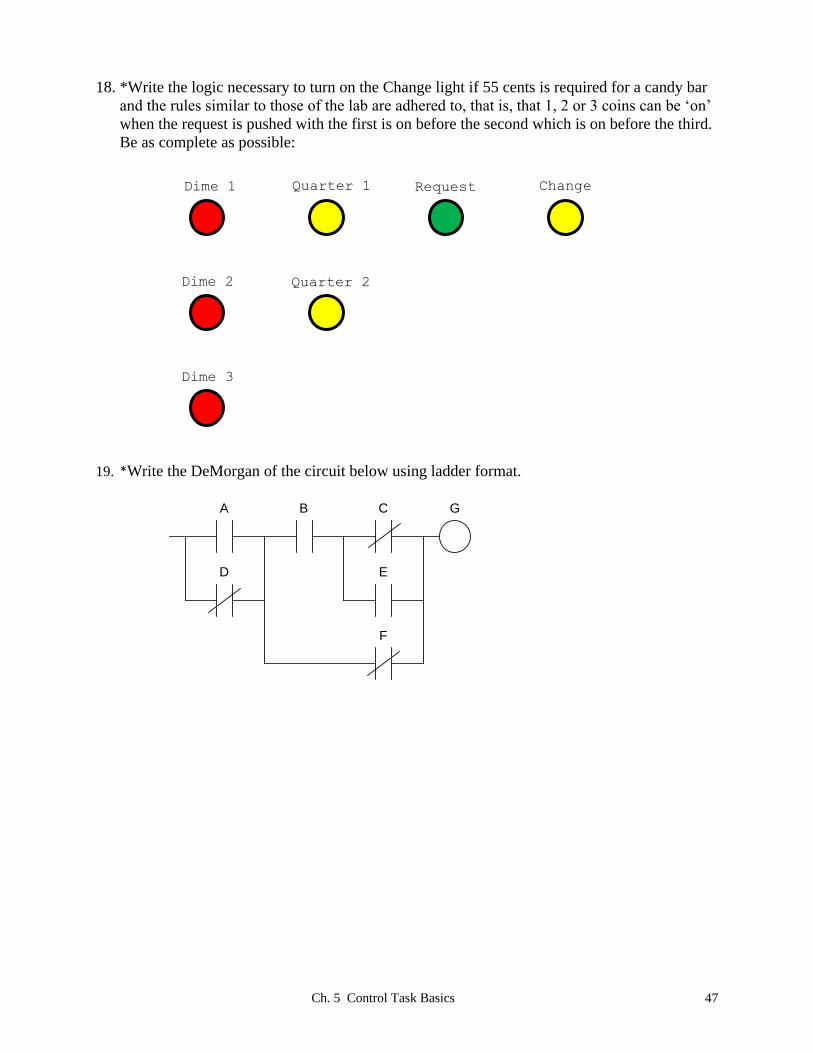
18. *Write the logic necessary to turn on the Change light if 55 cents is required for a candy bar
and the rules similar to those of the lab are adhered to, that is, that 1, 2 or 3 coins can be ‘on’
when the request is pushed with the first is on before the second which is on before the third.
Be as complete as possible:
19. *Write the DeMorgan of the circuit below using ladder format.
B
E
A C G
D
F
Quarter 1
Dime 2
Dime 3
Dime 1
Quarter 2
Request Change
Ch. 5 Control Task Basics 48
Lab 5.1 The Coin Changer
Implement a program to control a coin changer. A coin changer is built to return change plus
dispense a $.35 candy bar. No more than three coins are to ever be used (There is no need to
count the number of coins entered). Coins to be used are dimes and quarters. Write a program
to accept or reject the sale based on the coins rendered. Coins rendered are checked by inputs on
using push buttons or selector switches when the Request Candy Bar button is pushed.
Assume dime 2 is not allowed until dime 1 is on. Assume dime 3 is not allowed until dime 2 is
on. That is, dimes enter by filling the slot for dime 1, then dime 2 and finally dime 3.
The same sequence is used for quarters.
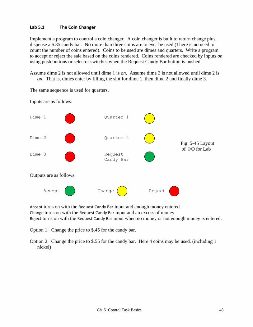
Inputs are as follows:
Dime 1 Quarter 1
Dime 2 Quarter 2
Fig. 5-45 Layout
of I/O for Lab Dime 3 Request
Candy Bar
Outputs are as follows:
Accept Change Reject
Accept turns on with the Request Candy Bar input and enough money entered.
Change turns on with the Request Candy Bar input and an excess of money.
Reject turns on with the Request Candy Bar input when no money or not enough money is entered.
Option 1: Change the price to $.45 for the candy bar.
Option 2: Change the price to $.55 for the candy bar. Here 4 coins may be used. (including 1