OBJECTIVE QUESTIONS (GATE, IES, IAS) Previous 20-Years GATE Questions Beam Deflection GATE-1. A lean elastic beam of given flexural rigidity, EI, is loaded by a single force F as shown in figure. How many boundary conditions are necessary to determine the deflected centre line of the beam? (a) 5 (b) 4 (c) 3 (d) 2 [GATE-1999] GATE-1. Ans. (d) 2 2 dy EI M dx . Since it is second order differential equation so we need two boundary conditions to solve it. Double Integration Method GATE-2. A simply supported beam carrying a concentrated load W at mid-span deflects by 1 under the load. If the same beam carries the load W such that it is distributed uniformly over entire length and undergoes a deflection 2 at the mid span. The ratio 1: 2 is: [IES-1995; GATE-1994] (a) 2: 1 (b) 2 : 1 (c) 1: 1 (d) 1: 2 GATE-2. Ans. (d) 3 1 Wl 48EI and 4 3 2 W 5 l 5Wl l 384EI 384EI Therefore 1: 2 = 5: 8 GATE-3. A simply supported laterally loaded beam was found to deflect more than a specified value. [GATE-2003] Which of the following measures will reduce the deflection? (a) Increase the area moment of inertia (b) Increase the span of the beam (c) Select a different material having lesser modulus of elasticity (d) Magnitude of the load to be increased GATE-3. Ans. (a) Maximum deflection ( ) = 3 Wl 48EI To reduce, , increase the area moment of Inertia. Page 225 of 429
Transcript
Chapter-5 Deflection of Beam S K Mondal’s
OBJECTIVE QUESTIONS (GATE, IES, IAS)
Previous 20-Years GATE Questions
Beam Deflection GATE-1. A lean elastic beam of given flexural
rigidity, EI, is loaded by a single force F as shown in figure. How many boundary conditions are necessary to determine the deflected centre line of the beam?
(a) 5 (b) 4 (c) 3 (d) 2
[GATE-1999]
GATE-1. Ans. (d)2
2
d yEI Mdx
. Since it is second order differential equation so we need two boundary
conditions to solve it.
Double Integration Method GATE-2. A simply supported beam carrying a concentrated load W at mid-span deflects
by 1 under the load. If the same beam carries the load W such that it is distributed uniformly over entire length and undergoes a deflection 2 at the mid span. The ratio 1: 2 is: [IES-1995; GATE-1994]
(a) 2: 1 (b) 2 : 1 (c) 1: 1 (d) 1: 2
GATE-2. Ans. (d) 3
1Wl48EI
and
43
2
W5 l5Wll
384EI 384EI Therefore 1: 2 = 5: 8
GATE-3. A simply supported laterally loaded beam was found to deflect more than a specified value. [GATE-2003]
Which of the following measures will reduce the deflection? (a) Increase the area moment of inertia (b) Increase the span of the beam (c) Select a different material having lesser modulus of elasticity (d) Magnitude of the load to be increased
GATE-3. Ans. (a) Maximum deflection ( ) = 3Wl
48EI To reduce, , increase the area moment of Inertia.
Page 225 of 429
Chapter-5 Deflection of Beam S K Mondal’s
Previous 20-Years IES Questions
Double Integration Method IES-1. Consider the following statements: [IES-2003] In a cantilever subjected to a concentrated load at the free end 1. The bending stress is maximum at the free end 2. The maximum shear stress is constant along the length of the beam 3. The slope of the elastic curve is zero at the fixed end
Which of these statements are correct? (a) 1, 2 and 3 (b) 2 and 3 (c) 1 and 3 (d) 1 and 2 IES-1. Ans. (b)
IES-2. A cantilever of length L, moment of inertia I. Young's modulus E carries a concentrated load W at the middle of its length. The slope of cantilever at the free end is: [IES-2001]
(a) 2
2WLEI
(b) 2
4WLEI
(c) 2
8WLEI
(d) 2
16WLEI
IES-2. Ans. (c)
2
222 8
LWWL
EI EI
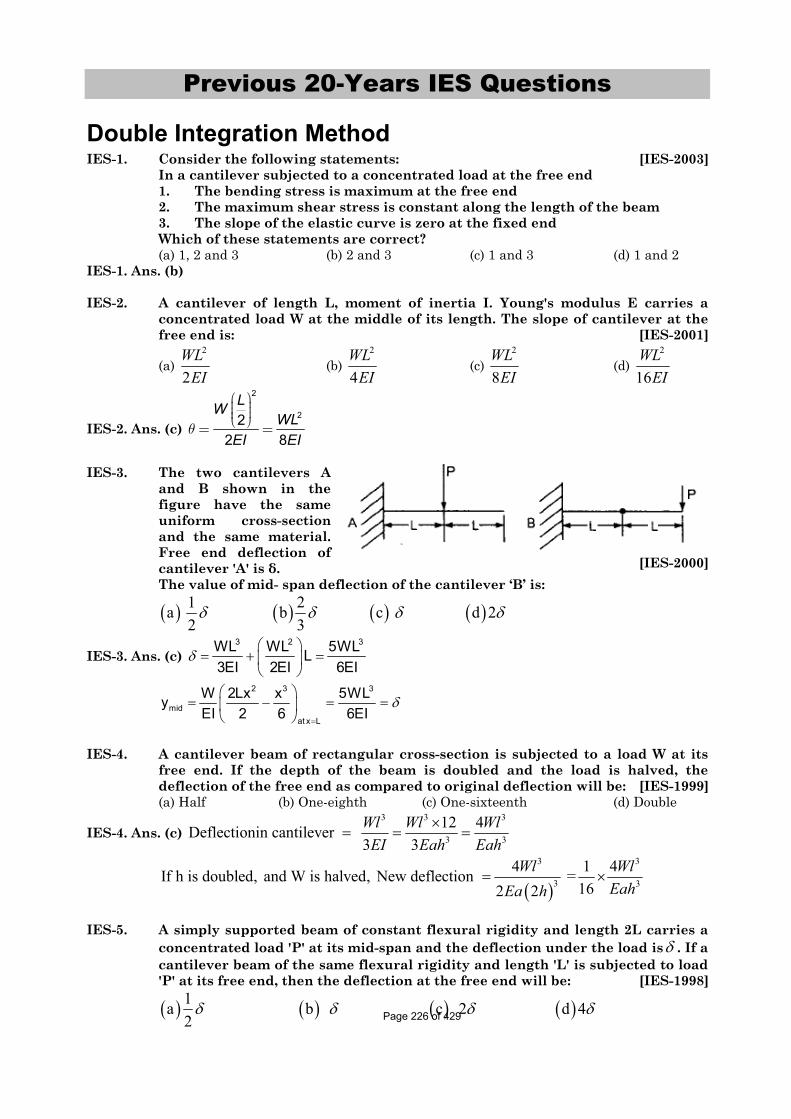
IES-3. The two cantilevers A and B shown in the figure have the same uniform cross-section and the same material. Free end deflection of cantilever 'A' is . [IES-2000]
The value of mid- span deflection of the cantilever ‘B’ is: 1 2a b c d 2 2 3
IES-3. Ans. (c)3 2 3WL WL 5WLL
3EI 2EI 6EI2 3 3
midat x L
W 2Lx x 5WLyEI 2 6 6EI
IES-4. A cantilever beam of rectangular cross-section is subjected to a load W at its free end. If the depth of the beam is doubled and the load is halved, the deflection of the free end as compared to original deflection will be: [IES-1999]
4 1 4If h is doubled, and W is halved, New deflection =162 2
Wl WlEahEa h
IES-5. A simply supported beam of constant flexural rigidity and length 2L carries a concentrated load 'P' at its mid-span and the deflection under the load is . If a cantilever beam of the same flexural rigidity and length 'L' is subjected to load 'P' at its free end, then the deflection at the free end will be: [IES-1998]
1a b c 2 d 4 2 Page 226 of 429
Chapter-5 Deflection of Beam S K Mondal’s
IES-5. Ans. (c)3 32
for simply supported beam48 6W L WL
EI EI3
and deflection for Cantilever 23WLEI
IES-6. Two identical cantilevers are loaded as shown in the respective figures. If slope at the free end of the cantilever in figure E is , the slope at free and of the cantilever in figure F will be:
Figure E Figure F
[IES-1997]
(a)13
(b) 12
(c) 23
(d)
IES-6. Ans. (d) When a B. M is applied at the free end of cantilever, 2/ 2
2PL LML PL
EI EI EI
When a cantilever is subjected to a single concentrated load at free end, then 2
2PLEI
IES-7. A cantilever beam carries a load W uniformly distributed over its entire length. If the same load is placed at the free end of the same cantilever, then the ratio of maximum deflection in the first case to that in the second case will be:
[IES-1996] (a) 3/8 (b) 8/3 (c) 5/8 (d) 8/5
IES-7. Ans. (a)3 3 3
8 3 8Wl WlEI EI
IES-8. The given figure shows a cantilever of span 'L' subjected to a concentrated load 'P' and a moment 'M' at the free end. Deflection at the free end is given by
[IES-1996]
(a) 2 2
2 3PL MLEI EI
(b) 2 3
2 3ML PLEI EI
(c) 2 3
3 2ML PLEI EI
(d) 2 3
2 48ML PLEI EI
IES-8. Ans. (b)
IES-9. For a cantilever beam of length 'L', flexural rigidity EI and loaded at its free end by a concentrated load W, match List I with List II and select the correct answer. [IES-1996]List I List II
A. Maximum bending moment 1. Wl B. Strain energy 2. Wl2/2EI C. Maximum slope 3. Wl3/3EI D. Maximum deflection 4. W2l2/6EI Codes: A B C D A B C D (a) 1 4 3 2 (b) 1 4 2 3 (c) 4 2 1 3 (d) 4 3 1 2
IES-9. Ans. (b)
IES-10. Maximum deflection of a cantilever beam of length ‘l’ carrying uniformly distributed load w per unit length will be: [IES- 2008]Page 227 of 429
Chapter-5 Deflection of Beam S K Mondal’s (a) wl4/ (EI) (b) w l4/ (4 EI) (c) w l4/ (8 EI) (d) w l4/ (384 EI) [Where E = modulus of elasticity of beam material and I = moment of inertia of beam
cross-section]IES-10. Ans. (c)
IES-11. A cantilever beam of length ‘l’ is subjected to a concentrated load P at a distance of l/3 from the free end. What is the deflection of the free end of the beam? (EI is the flexural rigidity) [IES-2004]
(a) 32
81PlEI
(b) 33
81PlEI
(c) 314
81PlEI
(d) 315
81PlEI
IES-11. Ans. (d)
A
3 3
2
2
max
3
3
Moment Area method gives us1 2Pl 2l l 4 l
Area 2 3 3 3 9xEI EI
Pl 2 7 14 PlEI 9 9 81 EI
2lWWa l a l 2l / 33Alternatively YEI 2 6 EI 2 6
9 2Wl 4EI 9 18
14 Wl81 EI
IES-12. A 2 m long beam BC carries a single concentrated load at its mid-span and is simply supported at its ends by two cantilevers AB = 1 m long and CD = 2 m long as shown in the figure.
The shear force at end A of the cantilever AB will be
(a) Zero (b) 40 kg (c) 50 kg (d) 60 kg [IES-1997]
IES-12. Ans. (c) Reaction force on B and C is same 100/2 = 50 kg. And we know that shear force is same throughout its length and equal to load at free end.
IES-13. Assertion (A): In a simply supported beam subjected to a concentrated load P at mid-span, the elastic curve slope becomes zero under the load. [IES-2003]
Reason (R): The deflection of the beam is maximum at mid-span. (a) Both A and R are individually true and R is the correct explanation of A (b) Both A and R are individually true but R is NOT the correct explanation of A (c) A is true but R is false (d) A is false but R is true IES-13. Ans. (a)
IES-14. At a certain section at a distance 'x' from one of the supports of a simply supported beam, the intensity of loading, bending moment and shear force arc Wx, Mx and Vx respectively. If the intensity of loading is varying continuously along the length of the beam, then the invalid relation is: [IES-2000]
2
2a Slope b c dx x x xx x x x
x
M dM d M dVQ V W WV dx dx dx
IES-14. Ans. (a)
Page 228 of 429
Chapter-5 Deflection of Beam S K Mondal’s IES-15. The bending moment equation, as a function of distance x measured from the
left end, for a simply supported beam of span L m carrying a uniformly distributed load of intensity w N/m will be given by [IES-1999]
3 2
2 3 2
wL w wL wa M= L-x - L-x Nm b M= x - x Nm 2 2 2 2
wL w wL wLxc M= L-x - L-x Nm d M= x - Nm 2 2 2 2
IES-15. Ans. (b)
IES-16. A simply supported beam with width 'b' and depth ’d’ carries a central load W and undergoes deflection at the centre. If the width and depth are interchanged, the deflection at the centre of the beam would attain the value
[IES-1997]2 3 3/2
a b c d d d d db b b b
IES-16. Ans. (b) Deflection at center 3 3
3
Wl Wl48EI bd48E
123 3 3 2 2
2 23 3In second case,deflection
4848 48
12 12
Wl Wl Wl d dEI b bdb bdE E
IES-17. A simply supported beam of rectangular section 4 cm by 6 cm carries a mid-span concentrated load such that the 6 cm side lies parallel to line of action of loading; deflection under the load is . If the beam is now supported with the 4 cm side parallel to line of action of loading, the deflection under the load will be: [IES-1993]
(a) 0.44 (b) 0.67 (c) 1.5 (d) 2.25 IES-17. Ans. (d) Use above explanation
IES-18. A simply supported beam carrying a concentrated load W at mid-span deflects by 1 under the load. If the same beam carries the load W such that it is distributed uniformly over entire length and undergoes a deflection 2 at the mid span. The ratio 1: 2 is: [IES-1995; GATE-1994]
(a) 2: 1 (b) 2 : 1 (c) 1: 1 (d) 1: 2
IES-18. Ans. (d) 3
1Wl48EI
and
43
2
W5 l5Wll
384EI 384EI Therefore 1: 2 = 5: 8
Moment Area Method IES-19. Match List-I with List-II and select the correct answer using the codes given
below the Lists: [IES-1997] List-I List-II
A. Toughness 1. Moment area method B. Endurance strength 2. HardnessC. Resistance to abrasion 3. Energy absorbed before fracture in
a tension test D. Deflection in a beam 4. Fatigue loading Code: A B C D A B C D
Slope and Deflection at a Section IAS-1. Which one of the following is represented by the area of the S.F diagram from
one end upto a given location on the beam? [IAS-2004] (a) B.M. at the location (b) Load at the location (c) Slope at the location (d) Deflection at the location IAS-1. Ans. (a)
Double Integration Method IAS-2. Which one of the following is the correct statement? [IAS-2007]
If for a beam 0dMdx
for its whole length, the beam is a cantilever:
(a) Free from any load (b) Subjected to a concentrated load at its free end (c) Subjected to an end moment (d) Subjected to a udl over its whole span IAS-2. Ans. (c) udl or point load both vary with x. But
if we apply Bending Moment (M) = const.
and 0dMdx
IAS-3. In a cantilever beam, if the length is doubled while keeping the cross-section and the concentrated load acting at the free end the same, the deflection at the free end will increase by [IAS-1996]
(a) 2.66 times (b) 3 times (c) 6 times (d) 8 times IAS-3. Ans. (d)
333 2 2
1 1
LPL L 83EI L
Conjugate Beam Method IAS-4. By conjugate beam method, the slope at any section of an actual beam is equal
to: [IAS-2002] (a) EI times the S.F. of the conjugate beam (b) EI times the B.M. of the conjugate beam (c) S.F. of conjugate beam (d) B.M. of the conjugate beamIAS-4. Ans. (c)
IAS-5. I = 375 × 10-6 m4; l = 0.5 m E = 200 GPa Determine the stiffness of the
[IES-2002]IAS-5. Ans. (c) Stiffness means required load for unit deformation. BMD of the given beam
Page 230 of 429
Chapter-5 Deflection of Beam S K Mondal’s
Loading diagram of conjugate beam
The deflection at the free end of the actual beam = BM of the at fixed point of conjugate beam
31 2 1 2 32 3 2 2 2 2 3 2
ML L WL L WL L WLy L L L L LEI EI EI EI
Or stiffness = 9 6
103 3
2 200 10 375 102 4 10 /3 3 0.5
W EI N my L
Page 231 of 429
Chapter-5 Deflection of Beam S K Mondal’s
Previous Conventional Questions with Answers
Conventional Question GATE-1999 Question: Consider the signboard mounting shown in figure below. The wind load
acting perpendicular to the plane of the figure is F = 100 N. We wish to limit the deflection, due to bending, at point A of the hollow cylindrical pole of outer diameter 150 mm to 5 mm. Find the wall thickness for the pole. [Assume E = 2.0 X 10¹¹ N/m2]
Answer: Given: F = 100 N; d0 = 150 mm, 0.15 my = 5 mm; E = 2.0 X 1O11 N/m2
Thickness of pole, t The system of signboard mounting can be considered as a cantilever loaded at A i.e. W
= 100 N and also having anticlockwise moment of M = 100 x 1 = 100 Nm at the free end. Deflection of cantilever having concentrated load at the free end,
Conventional Question IES-2003 Question: Find the slope and deflection at the free end of a cantilever beam of length
6m as loaded shown in figure below, using method of superposition. Evaluate their numerical value using E = 200 GPa, I = 1×10⁻⁴ m4 and W = 1 kN.
Page 232 of 429
Chapter-5 Deflection of Beam S K Mondal’s Answer: We have to use superposition
theory.1st consider
33
2 2
(3 ) 2 83 3
(3 ).2 62 2
c
c
WPL WEI EI EI
PL W WEI EI EI
1 c8W 6 32 at A due to this load( ) = .(6 2) = 4EIc
W WDeflectionEI EI
2
nd
3
B
2
2 consider:2 4 128
3 3(2 ) 4 16
2 at A due to this load( )
224W = (6 4)=3EI
B
B B
W WEI EI
W WEI EI
Deflection
.
3
3
2
A
6 72( )3
6 18 2
rd3 consider :
AW W
EI EIW W
EI EI
1
3
A 9 4
2 3
3
9 4
Apply superpositioning formula
40 106 16 18 40=200 10 10
32 224 72 40 563×W=3 3EI
563×(10 ) = 8.93 m m3 (200 10 ) 10
B cW W W WEI EI EI EI
W W W WEI EI EI EI
Conventional Question IES-2002 Question: If two cantilever beams of identical dimensions but made of mild steel and
grey cast iron are subjected to same point load at the free end, within elastic limit, which one will deflect more and why?
Answer: Grey cost iron will deflect more.
We know that a cantilever beam of length 'L' end load 'P' will deflect at free end
( ) = 3
3PLEI
Page 233 of 429
Chapter-5 Deflection of Beam S K Mondal’s
Mild steel
1
125 and E 200 Cast Iron
EE GPa GPa
Conventional Question IES-1997 Question: A uniform cantilever beam (EI = constant) of length L is carrying a
concentrated load P at its free end. What would be its slope at the (i) Free end and (ii) Built in end
Answer: (i) Free end, =2PL
2EI (ii) Built-in end, 0
L
P
Page 234 of 429
6. Bending Stress in Beam
Theory at a Glance (for IES, GATE, PSU)6.1 Euler Bernoulli’s Equation or (Bending stress formula) or Bending
Equation
M Ey I R
Where = Bending Stress
M = Bending Moment I = Moment of Inertia E = Modulus of elasticity R = Radius of curvature y = Distance of the fibre from NA (Neutral axis)
6.2 Assumptions in Simple Bending Theory All of the foregoing theory has been developed for the case of pure bending i.e. constant B.M along the length of the beam. In such case
The shear force at each c/s is zero.
Normal stress due to bending is only produced.
Beams are initially straight
The material is homogenous and isotropic i.e. it has a uniform composition and its mechanical properties are the same in all directions
The stress-strain relationship is linear and elastic
Young’s Modulus is the same in tension as in compression
Sections are symmetrical about the plane of bending
Sections which are plane before bending remain plane after bending
6.3
Page 235 of 429
Chapter-6 Bending Stress in Beam S K Mondal’s
1max t
McI
2min c
McI
(Minimum in sense of sign)
6.4 Section Modulus (Z)
IZ = y
Z is a function of beam c/s only
Z is other name of the strength of the beam
The strength of the beam sections depends mainly on the section modulus
The flexural formula may be written as, MZ
Rectangular c/s of width is "b" & depth "h" with sides horizontal, Z = 2
6bh
Square beam with sides horizontal, Z = 3
6a
Square c/s with diagonal horizontal, Z = 3
6 2a
Circular c/s of diameter "d", Z = 3
32d
Page 236 of 429
Chapter-6 Bending Stress in Beam S K Mondal’s A log diameter "d" is available. It is proposed to cut out a strongest beam from it. Then
Z = 2 2( )6
b d b
Therefore, Zmax =3 dfor b =
9 3bd
6.5 Flexural Rigidity (EI) Reflects both
Stiffness of the material (measured by E) Proportions of the c/s area (measured by I )
6.6 Axial Rigidity = EA
6.7 Beam of uniform strength It is one is which the maximum bending stress is same in every section along the longitudinal axis.
For it 2 bhMWhere b = Width of beam h = Height of beam
To make Beam of uniform strength the section of the beam may be varied by Keeping the width constant throughout the length and varying the depth, (Most widely used)Keeping the depth constant throughout the length and varying the width By varying both width and depth suitably.
6.8 Bending stress due to additional Axial thrust (P). A shaft may be subjected to a combined bending and axial thrust. This type of situation arises in various machine elements.
If P = Axial thrust
Then direct stress ( d ) = P / A (stress due to axial thrust)
This direct stress ( d ) may be tensile or compressive depending upon the load P is tensile or
compressive.
Page 237 of 429
Chapter-6 Bending Stress in Beam S K Mondal’s
And the bending stress ( b ) = MyI
is varying linearly from zero at centre and extremum (minimum
or maximum) at top and bottom fibres.
If P is compressive then
At top fibre P MyA I
(compressive)
At mid fibre PA
(compressive)
At bottom fibre PA
– MyI
(compressive)
6.9 Load acting eccentrically to one axis
max
P e yPA I
where ‘e’ is the eccentricity at which ‘P’ is act.
min
P e yPA I
Condition for No tension in any section
For no tension in any section, the eccentricity must not exceed 22k
d
[Where d = depth of the section; k = radius of gyration of c/s]
For rectangular section (b x h) , 6he i.e load will be 2
3he of the middle section.
For circular section of diameter ‘d’ , 8de i.e. diameter of the kernel, 2
4de
For hollow circular section of diameter ‘d’ , 2 2
8D de
Di.e. diameter of the kernel,
2 2
2 .4
D deD
Page 238 of 429
Chapter-6 Bending Stress in Beam S K Mondal’s
OBJECTIVE QUESTIONS (GATE, IES, IAS)
Previous 20-Years GATE Questions
Bending equation GATE-1. A cantilever beam has the
square cross section 10mm × 10 mm. It carries a transverse load of 10 N. Considering only the bottom fibres of the beam, the correct representation of the longitudinal variation of the bending stress is: [GATE-2005]
GATE-1. Ans. (a) x 4
10 x 0.005M MyM P.x or 60.(x) MPaI y I 0.01
12At x 0; 0At x 1m; 60MPa
And it is linear as x
GATE-2. Two beams, one having square cross section and another circular cross-section, are subjected to the same amount of bending moment. If the cross sectional area as well as the material of both the beams are the same then [GATE-2003]
(a) Maximum bending stress developed in both the beams is the same (b) The circular beam experiences more bending stress than the square one (c) The square beam experiences more bending stress than the circular one (d) As the material is same both the beams will experience same deformation
GATE-2. Ans. (b) M E My; or ;I y I
22
sq cir3 4 3 3 33
a dM M6M 32M 4 M 22.27M d2 2; a
1 4a d d a aa.a12 64
sq cir
Section Modulus GATE-3. Match the items in Columns I and II. [GATE-2006]
Column-I Column-II P. Addendum 1. Cam Q. Instantaneous centre of velocity 2. Beam Page 239 of 429
Chapter-6 Bending Stress in Beam S K Mondal’s R. Section modulus 3. Linkage S. Prime circle 4. Gear
(a) P – 4, Q – 2, R – 3, S – l (b) P – 4, Q – 3, R – 2, S – 1 (c) P – 3, Q – 2, R – 1, S – 4 (d) P – 3, Q – 4, R – 1, S – 2 GATE-3. Ans. (b)
Combined direct and bending stress GATE-4. For the component loaded with a force F as shown in the figure, the axial
stress at the corner point P is: [GATE-2008]
(a) 34)3(
bbLF
(b) 34)3(
bbLF
(c) 34)43(
bbLF
(d) 34)23(
bbLF
GATE-4. Ans. (d) Total Stress = Direct stress + Stress due to Moment
= 2 3
( )4 2 ( )
12
P My F F L b bA I b b b
Previous 20-Years IES Questions
Bending equation IES-1. Beam A is simply supported at its ends and carries udl of intensity w over its
entire length. It is made of steel having Young's modulus E. Beam B is cantilever and carries a udl of intensity w/4 over its entire length. It is made of brass having Young's modulus E/2. The two beams are of same length and have same cross-sectional area. If A and B denote the maximum bending stresses developed in beams A and B, respectively, then which one of the following is correct? [IES-2005]
(a) A/ B (b) A/ B < 1.0 (c) A/ B > 1.0 (d) A/ B depends on the shape of cross-section
IES-1. Ans. (d) Bending stress My , y and I both depends on theI
A
B
Shape of cross sec tion so depends on the shape of cross sec tion
IES-2. If the area of cross-section of a circular section beam is made four times, keeping the loads, length, support conditions and material of the beam unchanged, then the qualities (List-I) will change through different factors (List-II). Match the List-I with the List-II and select the correct answer using the code given below the Lists: [IES-2005]List-I List-II A. Maximum BM 1. 8
Page 240 of 429
Chapter-6 Bending Stress in Beam S K Mondal’s B. Deflection 2. 1 C. Bending Stress 3. 1/8 D. Section Modulus 4. 1/16 Codes: A B C D A B C D
(a) 3 1 2 4 (b) 2 4 3 1 (c) 3 4 2 1 (d) 2 1 3 4 IES-2. Ans. (b) Diameter will be double, D = 2d. A. Maximum BM will be unaffected
B. deflection ratio 4
1
2
EI d 1EI 4 16
C. Bending stress 3
24
1
M d / 2My d 1or Bending stress ratioI D 8d
64
D. Selection Modulus ratio3
2 2 1
1 1 1
Z I y D 8Z y I d
IES-3. Consider the following statements in case of beams: [IES-2002] 1. Rate of change of shear force is equal to the rate of loading at a particular
section 2. Rate of change of bending moment is equal to the shear force at a
particular suction. 3. Maximum shear force in a beam occurs at a point where bending moment
is either zero or bending moment changes sign Which of the above statements are correct?
(a) 1 alone (b) 2 alone (c) 1 and 2 (d) 1, 2 and 3 IES-3. Ans. (c)
IES-4. Match List-I with List-II and select the correct answer using the code given below the Lists: [IES-2006]List-I (State of Stress) List-II (Kind of Loading)
1. Combined bending and torsion of circular shaft
2. Torsion of circular shaft
3. Thin cylinder subjected to internal pressure
4. Tie bar subjected to tensile force
Codes: A B C D A B C D (a) 2 1 3 4 (b) 3 4 2 1 (c) 2 4 3 1 (d) 3 1 2 4 IES-4. Ans. (c)
Page 241 of 429
Chapter-6 Bending Stress in Beam S K Mondal’s
Section Modulus IES-5. Two beams of equal cross-sectional area are subjected to equal bending
moment. If one beam has square cross-section and the other has circular section, then [IES-1999]
(a) Both beams will be equally strong (b) Circular section beam will be stronger (c) Square section beam will be stronger (d) The strength of the beam will depend on the nature of loading
IES-5. Ans. (b) If D is diameter of circle and 'a' the side of square section, 2 2 44d a or d a
Z for circular section = 2 3 3
; and Z for square section =32 64d a a
IES-6. A beam cross-section is used in two different orientations as shown in the given figure:
Bending moments applied to the beam in both cases are same. The maximum bending stresses induced in cases (A) and (B) are related as:
(a) 4A B (b) 2A B
(c) 2B
A (d) 4B
A [IES-1997]
IES-6. Ans. (b) Z for rectangular section is 2
6bd
,
2
23 32 2,
6 24 6 12A B
b bb bb bZ Z
3 3
. . , 224 12A A B B A B A Bb bM Z Z or or
IES-7. A horizontal beam with square cross-section is simply supported with sides of the square horizontal and vertical and carries a distributed loading that produces maximum bending stress a in the beam. When the beam is placed with one of the diagonals horizontal the maximum bending stress will be:
[IES-1993]1(a) (b) (c) 2 (d) 22
IES-7. Ans. (c) Bending stress = MZ
For rectangular beam with sides horizontal and vertical, Z = 3
6a
For same section with diagonal horizontal, Z =3
6 2a
Ratio of two stresses = 2IES-8. Which one of the following combinations of angles will carry the maximum
load as a column? [IES-1994]
Page 242 of 429
Chapter-6 Bending Stress in Beam S K Mondal’s
IES-8. Ans. (a)
IES-9. Assertion (A): For structures steel I-beams preferred to other shapes. [IES-1992]Reason (R): In I-beams a large portion of their cross-section is located far from the neutral axis.
(a) Both A and R are individually true and R is the correct explanation of A (b) Both A and R are individually true but R is NOT the correct explanation of A (c) A is true but R is false (d) A is false but R is true IES-9. Ans. (a)
Combined direct and bending stress IES-10. Assertion (A): A column subjected to eccentric load will have its stress at
centroid independent of the eccentricity. [IES-1994]Reason (R): Eccentric loads in columns produce torsion.
(a) Both A and R are individually true and R is the correct explanation of A (b) Both A and R are individually true but R is NOT the correct explanation of A (c) A is true but R is false (d) A is false but R is true IES-10. Ans. (c) A is true and R is false. IES-11. For the configuration of loading shown in the given figure, the stress in fibre
AB is given by: [IES-1995]
(a) P/A (tensile) (b) . .5
xx
P P eA I
(Compressive)
(c) . .5
xx
P P eA I
(Compressive) (d) P/A (Compressive)
IES-11. Ans. (b) (compressive), (tensile)d xx x
P My PkyA I I
Page 243 of 429
Chapter-6 Bending Stress in Beam S K Mondal’s IES-12. A column of square section 40 mm × 40
mm, fixed to the ground carries an eccentric load P of 1600 N as shown in the figure.
If the stress developed along the edge CD is –1.2 N/mm2, the stress along the edge AB will be:
(a) –1.2 N/mm2
(b) +1 N/mm2 (c) +0.8 N/mm2 (d) –0.8 N/mm2
[IES-1999]
IES-12. Ans. (d) Compressive stress at CD = 1.2 N/mm2 = 6 1600 61 1
IES-13. A short column of symmetric cross-section made of a brittle material is subjected to an eccentric vertical load P at an eccentricity e. To avoid tensile stress in the short column, the eccentricity e should be less than or equal to:
(a) h/12 (b) h/6 (c) h/3 (d) h/2
[IES-2001]IES-13. Ans. (b)
IES-14. A short column of external diameter D and internal diameter d carries an eccentric load W. Toe greatest eccentricity which the load can have without producing tension on the cross-section of the column would be: [IES-1999]
2 2 2 2 2 2
(a) (b) (c) (d)8 8 8 8
D d D d D d D dd D
IES-14. Ans. (c)
Page 244 of 429
Chapter-6 Bending Stress in Beam S K Mondal’s
Previous 20-Years IAS Questions
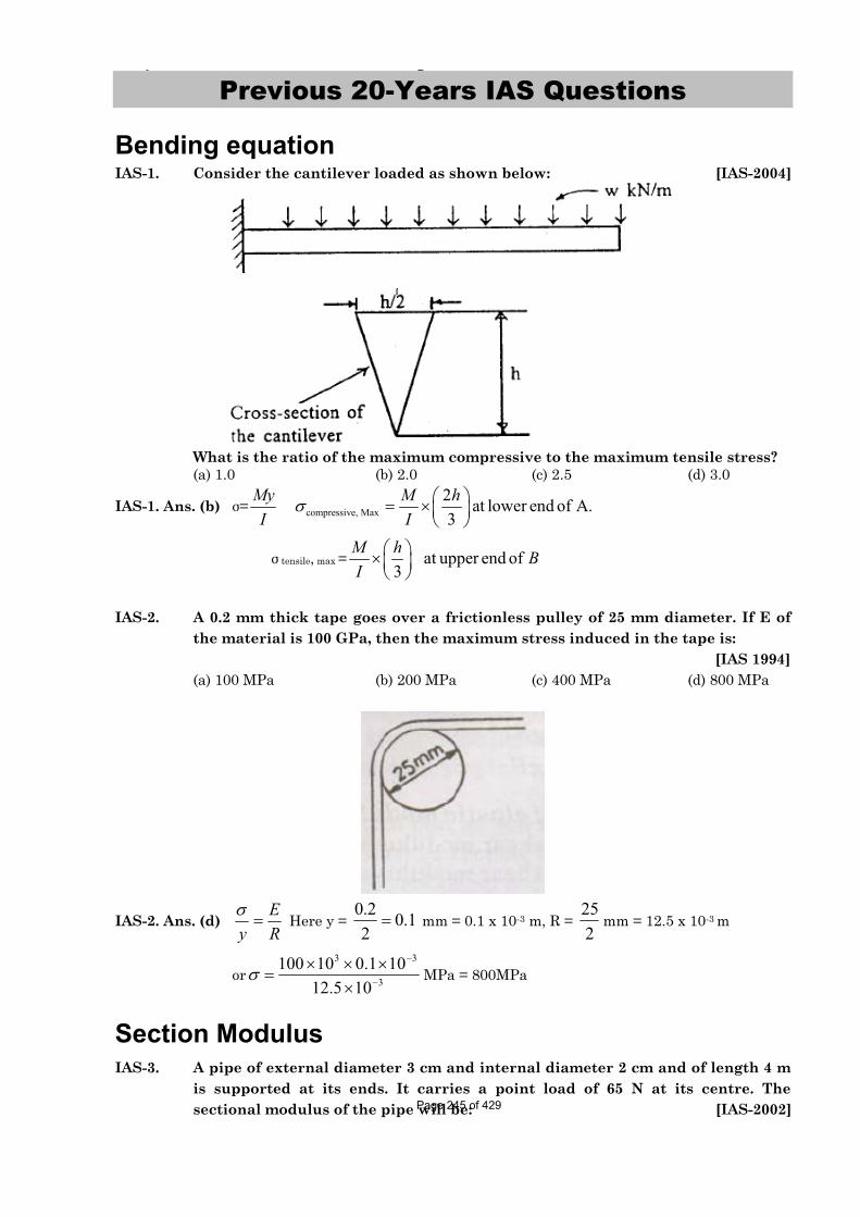
Bending equation IAS-1. Consider the cantilever loaded as shown below: [IAS-2004]
What is the ratio of the maximum compressive to the maximum tensile stress? (a) 1.0 (b) 2.0 (c) 2.5 (d) 3.0
IAS-1. Ans. (b) = compressive, Max2 at lower end of A.3
My M hI I
tensile, max = at upper end of3
M h BI
IAS-2. A 0.2 mm thick tape goes over a frictionless pulley of 25 mm diameter. If E of the material is 100 GPa, then the maximum stress induced in the tape is:
Section Modulus IAS-3. A pipe of external diameter 3 cm and internal diameter 2 cm and of length 4 m
is supported at its ends. It carries a point load of 65 N at its centre. The sectional modulus of the pipe will be: [IAS-2002] Page 245 of 429
Chapter-6 Bending Stress in Beam S K Mondal’s
(a) 36564cm (b) 365
32cm (c) 365
96cm (d) 365
128cm
IAS-3. Ans. (c)
4 4
33 2
64Section modulus (z) cm32
Iy
36596cm
IAS-4. A Cantilever beam of rectangular cross-section is 1m deep and 0.6 m thick. If the beam were to be 0.6 m deep and 1m thick, then the beam would. [IAS-1999]
(a) Be weakened 0.5 times (b) Be weakened 0.6 times (c) Be strengthened 0.6 times (d) Have the same strength as the original beam because the cross-sectional area
remains the same
IAS-4. Ans. (b) 3
31
I 0.6 1z 1.2my 0.5
33
2I 1 0.6and z 0.72my 0.3
2
1
z 0.72 0.6 timesz 1.2
IAS-5. A T-beam shown in the given figure is subjected to a bending moment such that plastic hinge forms. The distance of the neutral axis from D is (all dimensions are in mm)
(a) Zero (b) 109 mm (c) 125 mm (d) 170 mm
[IAS-2001]IAS-5. Ans. (b)
IAS-6. Assertion (A): I, T and channel sections are preferred for beams. [IAS-2000] Reason(R): A beam cross-section should be such that the greatest possible amount of area is as far away from the neutral axis as possible.
(a) Both A and R are individually true and R is the correct explanation of A (b) Both A and R are individually true but R is NOT the correct explanation of A (c) A is true but R is false (d) A is false but R is true IAS-6. Ans. (a) Because it will increase area moment of inertia, i.e. strength of the beam. Page 246 of 429
Chapter-6 Bending Stress in Beam S K Mondal’s
IAS-7. If the T-beam cross-section shown in the given figure has bending stress of 30 MPa in the top fiber, then the stress in the bottom fiber would be (G is centroid)
(a) Zero (b) 30 MPa (c) –80 MPa (d) 50 Mpa
[IAS-2000]
IAS-7. Ans. (c)1 1
1 2 12 2
2
30110 30 8030
M or y MPaI y y y
As top fibre in tension so bottom fibre will be in compression. IAS-8. Assertion (A): A square section is more economical in bending than the circular
section of same area of cross-section. [IAS-1999]Reason (R): The modulus of the square section is less than of circular section of same area of cross-section.
(a) Both A and R are individually true and R is the correct explanation of A (b) Both A and R are individually true but R is NOT the correct explanation of A (c) A is true but R is false (d) A is false but R is true IAS-8. ans. (c)
Bimetallic Strip IAS-9. A straight bimetallic strip of copper and steel is heated. It is free at ends. The
strip, will: [IAS-2002] (a) Expand and remain straight (b) Will not expand but will bend (c) Will expand and bend also (d) Twist onlyIAS-9. Ans. (c) As expansion of copper will be more than steel.
Combined direct and bending stress IAS-10. A short vertical column having a
square cross-section is subjected to an axial compressive force, centre of pressure of which passes through point R as shown in the above figure. Maximum compressive stress occurs at point
(a) S (b) Q (c) R (d) P
[IAS-2002]IAS-10. Ans. (a) As direct and bending both the stress is compressive here.
IAS-11. A strut's cross-sectional area A is subjected to load P a point S (h, k) as shown in the given figure. The stress at the point Q (x, y) is: [IAS-2000]
Page 247 of 429
Chapter-6 Bending Stress in Beam S K Mondal’s
(a) x y
P Phy PkxA I I
(b) y x
P Phx PkyA I I
(c) y x
P Phy PkxA I I
(d) y x
P Phx PkyA I I
IAS-11. Ans. (b) All stress are compressive, direct stress,
(compressive), (compressive)d xx x
P My PkyA I I
and (compressive)yy y
Mx PhxI I
Page 248 of 429
Chapter-6 Bending Stress in Beam S K Mondal’s
Previous Conventional Questions with Answers
Conventional Question IES-2008 Question: A Simply supported beam AB of span length 4 m supports a uniformly
distributed load of intensity q = 4 kN/m spread over the entire span and a concentrated load P = 2 kN placed at a distance of 1.5 m from left end A. The beam is constructed of a rectangular cross-section with width b = 10 cm and depth d = 20 cm. Determine the maximum tensile and compressive stresses developed in the beam to bending.
Answer:
AB
RA R
B
X
1.5
4m
2KN4kN/M
X
C/s
B=10cm
NA
A BR + R = 2 + 4×4.........(i)
A-R ×4 + 2×(4-1.5) + (4×4)×2=0.......(ii)
A B Aor R = 9.25 kN, R =18-R = 8.75 kN
if 0 x 2.5 m
x Bx M =R ×x - 4x. -2(x-2.5)2
2 2=8.75x - 2x - 2x + 5 = 6.75x - 2x + 5 ...(ii)
From (i) & (ii) we find out that bending movment at x = 2.1875 m in(i)gives maximum bending movement
2max
dM[Just find for both the casses]dx
M 8.25 2.1875 2 1875 9.57 7K kNm
Area movement of Inertia (I) = 3 3
5 40.1 0.2 6.6667 1012 12bh m
Maximum distance from NA is y = 10 cm = 0.1m3
2max 5
(9.57 10 ) 0.1 14.3556.6667 10
My N MPamI Therefore maximum tensile stress in the lowest point in the beam is 14.355 MPa and
maximum compressive stress in the topmost fiber of the beam is -14.355 MPa.
Conventional Question IES-2007 Question: A simply supported beam made of rolled steel joist (I-section: 450mm ×
200mm) has a span of 5 m and it carriers a central concentrated load W. The flanges are strengthened by two 300mm × 20mm plates, one riveted to each flange over the entire length of the flanges. The second moment of area of the joist about the principal bending axis is 35060 cm4. Calculate Page 249 of 429
Chapter-6 Bending Stress in Beam S K Mondal’s (i) The greatest central load the beam will carry if the bending stress in the
300mm/20mm plates is not to exceed 125 MPa. (ii) The minimum length of the 300 mm plates required to restrict the
maximum bending stress is the flanges of the joist to 125 MPa. Answer:
Moment of Inertia of the total section about X-X (I) = moment of inertia of I –section + moment of inertia of the plates about X-X axis.
2330 2 45 235060 2 30 212 2 2
4101370 cm
6 8
(i) Greatest central point load(W):For a simply supported beam a concentrated load at centre.
WL 5M = 1.254 4
125 10 101370 10. 5171940.245
1.25W = 517194 or W = 413.76 kN
W W
IM Nmy
(ii) Suppose the cover plates are absent for a distance of x-meters from each support. Then at these points the bending moment must not exceed moment of resistance of ‘I’ section alone i.e
86
35060 10. 125 10 1788780.245
I Nmy
moment at x metres from each support Bending
Page 250 of 429
Chapter-6 Bending Stress in Beam S K Mondal’s W= 178878241760, 178878
2 0.86464
leaving 0.86464 m from each support, for themiddle 5 - 2×0.86464 = 3.27 m the cover plate should beprovided.
x
or x
or x mHence
Conventional Question IES-2002Question: A beam of rectangular cross-section 50 mm wide and 100 mm deep is simply
supported over a span of 1500 mm. It carries a concentrated load of 50 kN, 500 mm from the left support.
Calculate: (i) The maximum tensile stress in the beam and indicate where it occurs: (ii) The vertical deflection of the beam at a point 500 mm from the right
support. E for the material of the beam = 2 × 10⁵ MPa.Answer: Taking moment about L
RR 1500 50 500, 16.667, 50
50 16.667=33.333 kN
R
L R
L
or R kNor R R
RTake a section from right R, x-xat a distance x.
xBending moment (M ) .RR x
Therefore maximum bending moment will occur at 'c' Mmax=16.667×1 KNm (i) Moment of Inertia of beam cross-section
334 6 40.050 (0.100)( ) = 4.1667×10
12 12bhI m m
3
2max 6
Applying bending equation0.00116.67 10
M 2or, / 200MPaI 4.1667 10
E My N my I
It will occure where M is maximum at point 'C'
2
x 2
(ii) Macaulay's method for determing the deflectionof the beam will be convenient as there is point load.
M 33.333 50 ( 0.5)d yEI x xdx
Page 251 of 429
Chapter-6 Bending Stress in Beam S K Mondal’s
2 22
1 22
2
3 31
1
Integrate both side we getd 50 EI 33.333 ( 0.5)
2 2 x=0, y=0 gives c 0 x=1.5, y=0 gives
0=5.556×(1.5) 8.333 1 1.5, 6.945
y x x c x cdx
atat
cor c
3 3
5 6 6
5.556 8.333( 0.5) 6.945 1 2.43
2.43, m = -2.9167 mm[downward so -ive](2×10 10 ) (4.1667 10 )
EIy x x
or y
Conventional Question AMIE-1997Question: If the beam cross-section is rectangular having a width of 75 mm, determine
the required depth such that maximum bending stress induced in the beam does not exceed 40 MN/m2
Answer: Given: b =75 mm =0·075 m, max =40 MN/m2
Depth of the beam, d: Figure below shows a rectangular section of width b = 0·075 m and depth d metres. The bending is considered to take place about the horizontal neutral axis N.A. shown in the figure. The maximum bending stress occurs at the outer
fibres of the rectangular section at a distance d2
above or below the neutral axis. Any
fibre at a distance y from N.A. is subjected to a bending stress, MyI
, where I
denotes the second moment of area of the rectangular section about the N.A. i.e.3bd
12.
At the outer fibres, y = d2
, the maximum bending stress there becomes
max 3 2
2
max
dMM2 i
bd bd12 6bdor M . (ii)6
For the condition of maximum strength i.e. maximum moment M, the product bd2 must be a maximum, since max is constant for a given material. To maximize the quantity bd2 we realise that it must be expressed in terms of one independent variable, say, b, and we may do this from the right angle triangle relationship.
Page 252 of 429
Chapter-6 Bending Stress in Beam S K Mondal’s 2 2 2
2 2 2
b d Dor d D b
Multiplying both sides by b, we get 2 2 3bd bD b To maximize bd2 we take the first derivative of expression with respect to b and set it
equal to zero, as follows: 2 2 3 2 2 2 2 2 2 2d dbd bD b D 3b b d 3b d 2b 0
db db Solving, we have, depth d 2 b ...(iii) This is the desired radio in order that the beam will carry a maximum moment M. It is to be noted that the expression appearing in the denominator of the right side of
eqn. (i) i. e. 2bd
6is the section modulus (Z) of a rectangular bar. Thus, it follows; the
section modulus is actually the quantity to be maximized for greatest strength of the beam.
Using the relation (iii), we have d = 2 x 0·075 = 0·0106 m
Now, M = max x Z = max x2bd
6 Substituting the values, we get
M = 40 × 20.075 0.106
6 = 0.005618 MNm
2max
M 0.005618 40MN / mZ 0.075 0.106 2 / 6
Hence, the required depth d = 0·106 m = 106 mm
Page 253 of 429
7. Shear Stress in Beam
Theory at a Glance (for IES, GATE, PSU)1. Shear stress in bending ( )
= vQIb
Where, V = Shear force = dMdx
Q = Statical moment = 1
1
c
y
ydA
I = Moment of inertia b = Width of beam c/s.
2. Statical Moment (Q)
Q=1
1
c
y
ydA= Shaded Area × distance of the centroid of the shaded area from the neutral axis of
the c/s.
3. Variation of shear stressSection Diagram Position of
max
max
Rectangular N.Amax =
32VA
max 1.5 mean
NA
Circular N.A
max43 mean
Page 254 of 429
Chapter-7 Shear Stress in Beam S K Mondal’s Triangular
6h
from N.A max 1.5 mean
NA = 1.33 mean
Trapezoidal
6h
from N.A
Section Diagram max
Uni form I-Section
In Flange,
( max )2
11
2 1max
2 8h
hy
V hI
1 2max hy
o
In Web
1
2 2 2max 1 1 1( )
8y o
v b h h thIt
1
221m 1
2 8him y
vb h hIt
4. Variation of shear stress for some more section [Asked in different examinations] Non uniform I-Section Diagonally placed square section
L-section Hollow circle
T-section Cross
Page 255 of 429
Chapter-7 Shear Stress in Beam S K Mondal’s
5. Rectangular section
Maximum shear stress for rectangular beam: max =32VA
For this, A is the area of the entire cross section
Maximum shear occurs at the neutral axis
Shear is zero at the top and bottom of beam
6. Shear stress in beams of thin walled profile section. Shear stress at any point in the wall distance "s" from the free edge
B
Shearing occurs here
A
Vx
O
force = Thickness of the section I = Moment of inrertia about NA
sx
o
x
V ydAIt
where V Shear
Shear Flow (q)
q =
sx
NA o
Vt ydAI
Shear Force (F)
Page 256 of 429
Chapter-7 Shear Stress in Beam S K Mondal’s
F= qds
Shear Centre (e) Point of application of shear stress resultant
Page 257 of 429
Chapter-7 Shear Stress in Beam S K Mondal’s
OBJECTIVE QUESTIONS (GATE, IES, IAS)
Previous 20-Years GATE Questions
Shear Stress Variation GATE-1. The transverse shear stress acting
in a beam of rectangular cross-section, subjected to a transverse shear load, is:
(a) Variable with maximum at the bottom of the beam
(b) Variable with maximum at the top of the beam
(c) Uniform (d) Variable with maximum on the
neutral axis
[IES-1995, GATE-2008]
GATE-1. Ans (d) mean23
max
GATE-2. The ratio of average shear stress to the maximum shear stress in a beam with a square cross-section is: [GATE-1994, 1998]
2 3(a) 1 (b) (c) (d) 23 2
GATE-2. Ans. (b)
max mean32
Previous 20-Years IES Questions
Shear Stress Variation IES-1. At a section of a beam, shear force is F with zero BM. The cross-section is
square with side a. Point A lies on neutral axis and point B is mid way between neutral axis and top edge, i.e. at distance a/4 above the neutral axis. If A and
B denote shear stresses at points A and B, then what is the value of A / B?[IES-2005]
(a) 0 (b) ¾ (c) 4/3 (d) None of above
IES-1. Ans. (c)
22 2
32 2 A
4 3 2B 2
3
a a 3 VV y .a2 4VAy 3 V 42 aa 4y orIb 2 3a a 3 V aa . . a 412 2 4aPage 258 of 429
Chapter-7 Shear Stress in Beam S K Mondal’s
IES-2. A wooden beam of rectangular cross-section 10 cm deep by 5 cm wide carries maximum shear force of 2000 kg. Shear stress at neutral axis of the beam section is: [IES-1997]
IES-2. Ans. (c) Shear stress at neutral axis = 23 3 2000 60kg/cm2 2 10 5
Fbd
IES-3. In case of a beam of circular cross-section subjected to transverse loading, the maximum shear stress developed in the beam is greater than the average shear stress by: [IES-2006; 2008]
(a) 50% (b) 33% (c) 25% (d) 10% IES-3. Ans. (b) In the case of beams with circular cross-section, the ratio of the maximum shear
stress to average shear stress 4:3
IES-4. What is the nature of distribution of shear stress in a rectangular beam? [IES-1993, 2004; 2008]
(a) Linear (b) Parabolic (c) Hyperbolic (d) Elliptic IES-4. Ans. (b)
221
V h y4I 4
indicating a parabolic distribution of shear stress across the cross-
section.
IES-5. Which one of the following statements is correct? [IES 2007] When a rectangular section beam is loaded transversely along the length, shear
stress develops on (a) Top fibre of rectangular beam (b) Middle fibre of rectangular beam (c) Bottom fibre of rectangular beam (d) Every horizontal plane IES-5. Ans. (b)
IES-6. A beam having rectangular cross-section is subjected to an external loading. The average shear stress developed due to the external loading at a particular Page 259 of 429
Chapter-7 Shear Stress in Beam S K Mondal’s cross-section is avgt . What is the maximum shear stress developed at the same
cross-section due to the same loading? [IES-2009]
(a) 12 avgt (b) avgt (c)
32 avgt (d) 2 avgt
IES-6. Ans. (c)
Shear stress in a rectangular beam, maximum shear stress,
max (average)3F 1.5
2b. h
Shear stress in a circular beam, the maximum shear stress,
max (average)2
4F 433 d
4
IES-7. The transverse shear stress acting in a beam of rectangular cross-section, subjected to a transverse shear load, is:
(a) Variable with maximum at the bottom of the beam
(b) Variable with maximum at the top of the beam
(c) Uniform (d) Variable with maximum on the
neutral axis
[IES-1995, GATE-2008]
IES-7. Ans (d) mean23
max
IES-8.
A cantilever is loaded by a concentrated load P at the free end as shown. The shear stress in the element LMNOPQRS is under consideration. Which of the following figures represents the shear stress directions in the cantilever?
[IES-2002]
Page 260 of 429
Chapter-7 Shear Stress in Beam S K Mondal’s
IES-8. Ans. (d)
IES-9. In I-Section of a beam subjected to transverse shear force, the maximum shear stress is developed. [IES- 2008]
(a) At the centre of the web (b) At the top edge of the top flange (c) At the bottom edge of the top flange (d) None of the above IES-9. Ans. (a)
IES-10. The given figure (all dimensions are in mm) shows an I-Section of the beam. The shear stress at point P (very close to the bottom of the flange) is 12 MPa. The stress at point Q in the web (very close to the flange) is:
(a) Indeterminable due to incomplete data
(b) 60MPa (c) 18 MPa (d) 12 MPa
[IES-2001]IES-10. Ans. (b) IES-11. Assertion (A): In an I-Section beam subjected to concentrated loads, the
shearing force at any section of the beam is resisted mainly by the web portion. Reason (R): Average value of the shearing stress in the web is equal to the value of shearing stress in the flange. [IES-1995]
(a) Both A and R are individually true and R is the correct explanation of A (b) Both A and R are individually true but R is NOT the correct explanation of A (c) A is true but R is false (d) A is false but R is true IES-11. Ans. (c)
Shear stress distribution for different section IES-12. The shear stress distribution over a beam cross-
section is shown in the figure above. The beam is of (a) Equal flange I-Section (b) Unequal flange I-Section (c) Circular cross-section (d) T-section
[IES-2003]IES-12. Ans. (b)
Page 261 of 429
Chapter-7 Shear Stress in Beam S K Mondal’s
Previous 20-Years IAS Questions
Shear Stress Variation IAS-1. Consider the following statements: [IAS-2007] Two beams of identical cross-section but of different materials carry same
bending moment at a particular section, then 1. The maximum bending stress at that section in the two beams will be
same. 2. The maximum shearing stress at that section in the two beams will be
same. 3. Maximum bending stress at that section will depend upon the elastic
modulus of the beam material. 4. Curvature of the beam having greater value of E will be larger. Which of the statements given above are correct? (a) 1 and 2 only (b) 1, 3 and 4 (c) 1, 2 and 3 (d) 2, 3 and 4
IAS-1. Ans. (a) Bending stress =MyI
and shear stress ( ) =VAyIb
both of them does not depends
on material of beam.
IAS-2. In a loaded beam under bending [IAS-2003] (a) Both the maximum normal and the maximum shear stresses occur at the skin
fibres (b) Both the maximum normal and the maximum shear stresses occur the neutral axis (c) The maximum normal stress occurs at the skin fibres while the maximum shear
stress occurs at the neutral axis (d) The maximum normal stress occurs at the neutral axis while the maximum shear
stress occurs at the skin fibres IAS-2. Ans. (c)
221
V h y4I 4
indicating a parabolic distribution of shear stress across the cross-
section.
Shear stress distribution for different section IAS-3. Select the correct shear stress distribution diagram for a square beam with a
diagonal in a vertical position: [IAS-2002]Page 262 of 429
Chapter-7 Shear Stress in Beam S K Mondal’s
IAS-3. Ans. (d)
IAS-4. The distribution of shear stress of a beam is shown in the given figure. The cross-section of the beam is: [IAS-2000]
IAS-4. Ans. (b) IAS-5. A channel-section of the beam shown in the given figure carries a uniformly
distributed load. [IAS-2000]
Assertion (A): The line of action of the load passes through the centroid of the cross-section. The beam twists besides bending.
Reason (R): Twisting occurs since the line of action of the load does not pass through the web of the beam.
(a) Both A and R are individually true and R is the correct explanation of A (b) Both A and R are individually true but R is NOT the correct explanation of A
Page 263 of 429
Chapter-7 Shear Stress in Beam S K Mondal’s (c) A is true but R is false (d) A is false but R is true IAS-5. Ans. (c) Twisting occurs since the line of action of the load does not pass through the shear.
Page 264 of 429
Chapter-7 Shear Stress in Beam S K Mondal’s
Previous Conventional Questions with Answers
Conventional Question IES-2009 Q. (i)A cantilever of circular solid cross-section is fixed at one end and carries a
concentrated load P at the free end. The diameter at the free end is 200 mm and increases uniformly to 400 mm at the fixed end over a length of 2 m. At what distance from the free end will the bending stresses in the cantilever be maximum? Also calculate the value of the maximum bending stress if the concentrated load P = 30 kN [15-Marks]
Ans. We have M .... (i)y I
Taking distance x from the free end we have
3
4
M = 30x kN.m = 30x × 10 N.mxy = 100 + 200 1002
100 50x mmdand I = 64
Let d be the diameter at x from free end.
4
44
400 200200 x
264
200 100x mm
64 From equation (i), we have
3
3
4 12
3 12
100 50x 10
30x 10
200 100x 1064
960x 200 100x 10 ...... (ii)
3 12960x 200 100x 10
dFor max , 0dx
1210 960
4 3x 3 100 200 100x 1. 200 100x 0
- 300x + 200 + 100x = 0 x = 1m
Page 265 of 429
Chapter-7 Shear Stress in Beam S K Mondal’s 30kN
2000mm(2m)
200
400
Hence maximum bending stress occurs at the midway and from equation (ii), maximum bending stress
3 12
12
3
960 1 200 100 10
960 10 11.32 MPa300
Conventional Question IES-2006 Question: A timber beam 15 cm wide and 20 cm deep carries uniformly distributed load
over a span of 4 m and is simply supported. If the permissible stresses are 30 N/mm2 longitudinally and 3 N/mm2
transverse shear, calculate the maximum load which can be carried by the timber beam.
Nm
ω
20cmN/A
Answer:33
4 40.15 0.20Moment of inertia (I) 10 m
12 12bh
2 2
20Distance of neutral axis from the top surface 10cm 0.1 m2
We know that or
Where maximum bending moment due to uniformly4distributed load in simply supported beam ( ) 2
30 kN/mSo maximum load carring capacity of the beam = 15 kN/m (without fail).
Page 267 of 429
8. Fixed and Continuous Beam
Theory at a Glance (for IES, GATE, PSU)What is a beam? A (usually) horizontal structural member that is subjected to a load that tends to bend it.
Types of Beams
Simply supported beam Cantilever beam
Simply Supported Beams Cantilever Beam
Continuous Beam Single Overhang Beam
Double Overhang Beam Single Overhang Beam with internal hinge
Fixed Beam Continuous beam
Continuous beams Beams placed on more than 2 supports are called continuous beams. Continuous beams are used when the span of the beam is very large, deflection under each rigid support will be equal zero.
Analysis of Continuous Beams (Using 3-moment equation)
Stability of structure
If the equilibrium and geometry of structure is maintained under the action of forces than the
structure is said to be stable. Page 268 of 429
Chapter-8 Fixed and Continuous Beam Page-267
External stability of the structure is provided by the reaction at the supports. Internal stability is
provided by proper design and geometry of the member of the structure.
Statically determinate and indeterminate structures
Beams for which reaction forces and internal forces can be found out from static equilibrium
equations alone are called statically determinate beam.
Example:
RA
RB
P
i A .0, 0 and M 0 is sufficient to calculate R &i i BX Y R
Beams for which reaction forces and internal forces cannot be found out from static equilibrium
equations alone are called statically indeterminate beam. This type of beam requires deformation
equation in addition to static equilibrium equations to solve for unknown forces.
Example:
RA RB RcRD
P P
Page 269 of 429
Chapter-8 Fixed and Continuous Beam Page-268
Advantages of fixed ends or fixed supports Slope at the ends is zero.
Fixed beams are stiffer, stronger and more stable than SSB.
In case of fixed beams, fixed end moments will reduce the BM in each section.
The maximum deflection is reduced.
Bending moment diagram for fixed beamExample:
BMD for Continuous beams BMD for continuous beams can be obtained by superimposing the fixed end moments diagram over the free bending moment diagram.
Page 270 of 429
Chapter-8 Fixed and Continuous Beam Page-269
Three - moment Equation for continuous beams OR Clapeyron’s Three Moment Equation
Page 271 of 429
Chapter-8 Fixed and Continuous Beam Page-270
OBJECTIVE QUESTIONS (GATE, IES, IAS)
Previous 20-Years IES Questions
Overhanging Beam IES-1. An overhanging beam ABC is supported at points A and B, as shown in the
above figure. Find the maximum bending moment and the point where it occurs. [IES-2009]
(a) 6 kN-m at the right support (b) 6 kN-m at the left support (c) 4.5 kN-m at the right support (d) 4.5 kN-m at the midpoint
between the supports
IES-1. Ans. (a) Taking moment about A
B
B
B
A B
A
V 2 = 2 1 6 32V 2 18
V 10 kNV V 2 6 8kN
V 8 10 2 kN Maximum Bending Moment =
6 kN-m at the right support
IES-2. A beam of length 4 L is simply supported on two supports with equal overhangs of L on either sides and carries three equal loads, one each at free ends and the third at the mid-span. Which one of the following diagrams represents correct distribution of shearing force on the beam? [IES-2004]
IES-2. Ans. (d)
Page 272 of 429
Chapter-8 Fixed and Continuous Beam Page-271
They use opposite sign conversions but for correct sign remember S.F & B.M of cantilever is (-) ive.
IES-3. A horizontal beam carrying uniformly distributed load is supported with equal overhangs as shown in the given figure
The resultant bending moment at the mid-span shall be zero if a/b is: [IES-2001] (a) 3/4 (b) 2/3 (c) 1/2 (d) 1/3 IES-3. Ans. (c)
Previous 20-Years IAS Questions
Overhanging Beam IAS-1.
If the beam shown in the given figure is to have zero bending moment at its middle point, the overhang x should be: [IAS-2000]
(a) 2 / 4wl P (b) 2 / 6wl P (c) 2 / 8wl P (d) 2 /12wl P
IAS-1. Ans. (c)2c DwlR R P
Bending moment at mid point (M) = 2
02 4 2 2 8Dwl l l l wlR P x gives x
P
IAS-2. A beam carrying a uniformly distributed load rests on two supports 'b' apart with equal overhangs 'a' at each end. The ratio b/a for zero bending moment at mid-span is: [IAS-1997]
(a) 12
(b) 1 (c) 32
(d) 2 Page 273 of 429
Chapter-8 Fixed and Continuous Beam Page-272 IAS-2. Ans. (d)
(i) By similarity in the B.M diagram a must be b/2
(ii) By formula 2
2bM a 02 4
gives a = b/2
IAS-3. A beam carries a uniformly distributed load and is supported with two equal overhangs as shown in figure 'A'. Which one of the following correctly shows the bending moment diagram of the beam? [IAS 1994]
IAS-3. Ans. (a)
Page 274 of 429
Chapter-8 Fixed and Continuous Beam Page-273
Previous Conventional Questions with Answers
Conventional Question IES-2006 Question: What are statically determinate and in determinate beams? Illustrate each
case through examples. Answer: Beams for which reaction forces and internal forces can be found out from static
equilibrium equations alone are called statically determinate beam. Example:
RA
RB
P
i
A .
0, 0 and M 0 is sufficient
to calculate R &i i
B
X Y
R
Beams for which reaction forces and internal forces cannot be found out from static equilibrium equations alone are called statically indeterminate beam. This type of beam requires deformation equation in addition to static equilibrium equations to solve for unknown forces.
Example:
RA RB RcRD
P P
Page 275 of 429
9. Torsion
Theory at a Glance (for IES, GATE, PSU) • In machinery, the general term “shaft” refers to a member, usually of circular cross-
section, which supports gears, sprockets, wheels, rotors, etc., and which is subjected to
torsion and to transverse or axial loads acting singly or in combination.
• An “axle” is a rotating/non-rotating member that supports wheels, pulleys,… and
carries no torque.
• A “spindle” is a short shaft. Terms such as lineshaft, headshaft, stub shaft, transmission
shaft, countershaft, and flexible shaft are names associated with special usage.
Torsion of circular shafts
1. Equation for shafts subjected to torsion "T"
T G= =J L
τ θR
Torsion Equation
Where J = Polar moment of inertia
τ = Shear stress induced due to torsion T.
G = Modulus of rigidity
θ = Angular deflection of shaft
R, L = Shaft radius & length respectively
Assumptions
• The bar is acted upon by a pure torque.
• The section under consideration is remote from the point of application of the load and from
a change in diameter.
• Adjacent cross sections originally plane and parallel remain plane and parallel after
twisting, and any radial line remains straight.
• The material obeys Hooke’s law
• Cross-sections rotate as if rigid, i.e. every diameter rotates through the same angle
Page 276 of 429
Chapter-9 Torsion S K Mondal’s
2. Polar moment of inertia
• Solid shaft “J” = 4d
32π
• Hollow shaft, "J” = 4 4( )32π
−o id d
3. The polar section modulus
Zp= J / c, where c = r = D/2
• For a solid circular cross-section, Zp = π D3 / 16
• For a hollow circular cross-section, Zp = π (Do4 - Di4 ) / (16Do)
• Then, maxτ = T / Zp
• If design shears stress, dτ is known, required polar section modulus can be calculated from:
Zp = T / dτ
4. Power Transmission (P)
• P (in Watt ) = 2
60NTπ
As stated above, the polar second moment of area, J is defined as J = 2 3
0π r dr
Rz
For a solid shaft J = 24
24 32
4
0
4 4
π π πr R DRL
NMOQP
= = (6)
For a hollow shaft of internal radius r:
J = 2 3
0π r dr
Rz = 24 2 32
44 4 4 4π π πr
R r D dr
RLNMOQP
= − = −( ) c h (7)
Where D is the external and d is the internal diameter.
Page 277 of 429
Chapter-9 Torsion S K Mondal’s
• P (in hp) = 24500
NTπ (1 hp = 75 Kgm/sec).
[Where N = rpm; T = Torque in N-m.]
5. Safe diameter of Shaft (d) • Stiffness consideration
θ
=T G
J L
• Shear Stress consideration
T
J R
τ=
We take higher value of diameter of both cases above for overall safety if other parameters are given.
6. In twisting
• Solid shaft, maxτ = 3
16Tdπ
• Hollow shaft, maxτ = o4 4
16Td( )π −o id d
• Diameter of a shaft to have a maximum deflection "α " d = 4.9 × 4α
TL
G
[Where T in N-mm, L in mm, G in N/mm2]
7. Comparison of solid and hollow shaft • A Hollow shaft will transmit a greater torque than a solid shaft of the same weight & same
material because the average shear stress in the hollow shaft is smaller than the average
shear stress in the solid shaft
• max
max
( ) shaft 16( ) shaft 15ττ
=holloow
solid
o i
If solid shaft dia = DDHollow shaft, d = D, d = 2
⎡ ⎤⎢ ⎥⎢ ⎥⎣ ⎦
• Strength comparison (same weight, material, length and maxτ )
2
2
11
h
s
T n
T n n
+=
− Externaldiameter of hollow shaftWhere, n=
Internaldiameter of hollow shaft [ONGC-2005]
• Weight comparison (same Torque, material, length and maxτ )
( )( )
2 2/3
2/34
1
1h
s
n nW
W n
−=
− Externaldiameter of hollow shaftWhere, n=
Internaldiameter of hollow shaft [WBPSC-2003]
• Strain energy comparison (same weight, material, length and maxτ )
2
2
1h
s
U n
U n
+= 2
11n
= + Page 278 of 429
Chapter-9 Torsion S K Mondal’s
8. Shaft in series
1 2θ θ θ= +
Torque (T) is same in all section
Electrical analogy gives torque(T) = Current (I)
9. Shaft in parallel
1 2θ θ= and 1 2T T T= +
Electrical analogy gives torque(T) = Current (I)
10. Combined Bending and Torsion • In most practical transmission situations shafts which carry torque are also subjected to
bending, if only by virtue of the self-weight of the gears they carry. Many other practical
applications occur where bending and torsion arise simultaneously so that this type of
loading represents one of the major sources of complex stress situations.
• In the case of shafts, bending gives rise to tensile stress on one surface and compressive
stress on the opposite surface while torsion gives rise to pure shear throughout the shaft.
• For shafts subjected to the simultaneous application of a bending moment M and torque T
the principal stresses set up in the shaft can be shown to be equal to those produced by an
equivalent bending moment, of a certain value Me acting alone.
• Figure
• Maximum direct stress ( xσ ) & Shear stress ( ( )xyτ in element A
3
3
32
16
σπ
τπ
= +
=
x
xy
M P
d AT
d
• Principal normal stresses ( 1,2σ ) & Maximum shearing stress ( maxτ ) Page 279 of 429
Chapter-9 Torsion S K Mondal’s
1,2σ = 2
2
2 2σ σ τ⎛ ⎞± +⎜ ⎟
⎝ ⎠x x
xy
2
21 2max ( )
2 2σσ στ τ− ⎛ ⎞= = ± +⎜ ⎟⎝ ⎠
xxy
• Maximum Principal Stress ( maxσ ) & Maximum shear stress ( maxτ )
maxσ = 2 23
16π
⎡ ⎤+ +⎣ ⎦M M Td
maxτ = 2 23
16π
+M Td
• Location of Principal plane (θ )
θ = 11 tan2
− ⎛ ⎞⎜ ⎟⎝ ⎠
T
M
• Equivalent bending moment (Me) & Equivalent torsion (Te).
2 2
2
⎡ ⎤+ += ⎢ ⎥⎢ ⎥⎣ ⎦
e
M M TM
2 2= +eT M T
• Important Note
o Uses of the formulas are limited to cases in which both M & T are known. Under any
other condition Mohr’s circle is used.
• Safe diameter of shaft (d) on the basis of an allowable working stress.
o wσ in tension , d = 332 e
w
M
πσ
o wτ in shear , d= 316 e
w
T
πτ
11. Shaft subjected to twisting moment only • Figure
Page 280 of 429
Chapter-9 Torsion S K Mondal’s
• Normal force ( nF ) & Tangential for ( tF ) on inclined plane AB
[ ][ ]
sin + AC cos
× BC cos - AC sin
τ θ θ
τ θ θ
= − ×
=n
t
F BC
F
• Normal stress ( nσ ) & Tangential stress (shear stress) ( tσ ) on inclined plane AB.
nσ = sin 2τ θ−
tσ = 2τ θcos
• Maximum normal & shear stress on AB
θ ( nσ )max τ max
0 0 +τ
45° –τ 0
90 0 –τ
135 +τ 0
• Important Note
• Principal stresses at a point on the surface of the shaft = +τ , -τ , 0
i.e 1,2 sin2σ τ θ= ±
• Principal strains
1 2 3(1 ); (1 ); 0τ τμ μ∈ = + ∈ = − + ∈ =E E
• Volumetric strain,
1 2 3 0∈ =∈ +∈ +∈ =v
• No change in volume for a shaft subjected to pure torque.
12. Torsional Stresses in Non-Circular Cross-section Members • There are some applications in machinery for non-circular cross-section members and shafts
where a regular polygonal cross-section is useful in transmitting torque to a gear or pulley
that can have an axial change in position. Because no key or keyway is needed, the
possibility of a lost key is avoided.
• Saint Venant (1855) showed that maxτ in a rectangular b × c section bar occurs in the middle
of the longest side b and is of magnitude formula
max 2 21.83
/T T
b cbc bcτ
α⎛ ⎞= = +⎜ ⎟⎝ ⎠
Where b is the longer side and α factor that is function of the ratio b/c.
The angle of twist is given by Page 281 of 429
Chapter-9 Torsion S K Mondal’s
3Tlbc G
θβ
=
Where β is a function of the ratio b/c
Shear stress distribution in different cross-section
Rectangular c/s Elliptical c/s Triangular c/s
13. Torsion of thin walled tube • For a thin walled tube
Shear stress,02
τ = T
A t
Angle of twist, 2 O
sL
A G
τφ =
[Where S = length of mean centre line, OA = Area enclosed by mean centre line]
• Special Cases
o For circular c/s
3 22 ; ; 2π π π= = =oJ r t A r S r
[r = radius of mean Centre line and t = wall thickness]
2
. =2 r 2
τπ
∴ = =o
T T r T
t J A t
32τϕ
π= = =
o
TL L TL
GJ A JG r tG
o For square c/s of length of each side ‘b’ and thickness ‘t’
2
0
=4b A b
S
=
o For elliptical c/s ‘a’ and ‘b’ are the half axis lengths.
0
3 ( )2
A ab
S a b ab
π
π
=
⎡ ⎤≈ + −⎢ ⎥⎣ ⎦
Page 282 of 429
Chapter-9 Torsion S K Mondal’s
OBJECTIVE QUESTIONS (GATE, IES, IAS)
Previous 20-Years GATE Questions
Torsion Equation GATE-1. A solid circular shaft of 60 mm diameter transmits a torque of 1600 N.m. The
value of maximum shear stress developed is: [GATE-2004] (a) 37.72 MPa (b) 47.72 MPa (c) 57.72 MPa (d) 67.72 MPa
GATE-1. Ans. (a) 3
16Td
τπ
=
GATE-2. Maximum shear stress developed on the surface of a solid circular shaft under
pure torsion is 240 MPa. If the shaft diameter is doubled then the maximum shear stress developed corresponding to the same torque will be: [GATE-2003]
(a) 120 MPa (b) 60 MPa (c) 30 MPa (d) 15 MPa
GATE-2. Ans. (c) ( )3 3 3
16T 16T 16T 240, 240 if diameter doubled d 2d, then 30MPa8d d 2d
τ τπ π π
′ ′= = = = = =
GATE-3. A steel shaft 'A' of diameter 'd' and length 'l' is subjected to a torque ‘T’ Another
shaft 'B' made of aluminium of the same diameter 'd' and length 0.5l is also subjected to the same torque 'T'. The shear modulus of steel is 2.5 times the shear modulus of aluminium. The shear stress in the steel shaft is 100 MPa. The shear stress in the aluminium shaft, in MPa, is: [GATE-2000]
(a) 40 (b) 50 (c) 100 (d) 250
GATE-3. Ans. (c) 3
16Td
τπ
= as T & d both are same τ is same
GATE-4. For a circular shaft of diameter d subjected to torque T, the maximum value of
the shear stress is: [GATE-2006]
3 3 3 3
64 32 16 8(a) (b) (c) (d)T T T T
d d d dπ π π π
GATE-4. Ans. (c)
Power Transmitted by Shaft GATE-5. The diameter of shaft A is twice the diameter or shaft B and both are made of
the same material. Assuming both the shafts to rotate at the same speed, the maximum power transmitted by B is: [IES-2001; GATE-1994]
(a) The same as that of A (b) Half of A (c) 1/8th of A (d) 1/4th of A
GATE-5. Ans. (c) 3
3
2 N 16T dPower, P T and or T60 16dπ τπτ
π= × = =
3
3d 2 Nor P orP d16 60τπ π α= ×
Combined Bending and Torsion GATE-6. A solid shaft can resist a bending moment of 3.0 kNm and a twisting moment of
4.0 kNm together, then the maximum torque that can be applied is: [GATE-1996] (a) 7.0 kNm (b) 3.5 kNm (c)4.5 kNm (d) 5.0 kNm GATE-6. Ans. (d) Equivalent torque ( ) 2 2 2 2
eT M T 3 4 5kNm= + = + = Page 283 of 429
Chapter-9 Torsion S K Mondal’s
Comparison of Solid and Hollow Shafts GATE-7. The outside diameter of a hollow shaft is twice its inside diameter. The ratio of
its torque carrying capacity to that of a solid shaft of the same material and the same outside diameter is: [GATE-1993; IES-2001]
(a) 1516
(b) 34
(c) 12
(d) 1
16
GATE-7. Ans. (a) T G Jor T if is const. T JJ L R R
θ τ τ τ α= = =
44
h h
4
DD32 2T J 15
T J 16D32
π
π
⎡ ⎤⎛ ⎞−⎢ ⎥⎜ ⎟⎝ ⎠⎢ ⎥⎣ ⎦= = =
Shafts in Series GATE-8. A torque of 10 Nm is transmitted through a stepped shaft as shown in figure.
The torsional stiffness of individual sections of lengths MN, NO and OP are 20 Nm/rad, 30 Nm/rad and 60 Nm/rad respectively. The angular deflection between the ends M and P of the shaft is: [GATE-2004]
(a) 0.5 rad (b) 1.0 rad (c) 5.0 rad (d) 10.0 rad
GATE-8. Ans. (b) TLWe know that or T k. [let k tortional stiffness]GJ
θ θ= = =
NO OPMNMN NO OP
MN NO OP
T TT 10 10 10 1.0 radk k k 20 30 60
θ θ θ θ∴ = + + = + + = + + =
Shafts in Parallel GATE-9. The two shafts AB and BC, of equal
length and diameters d and 2d, are made of the same material. They are joined at B through a shaft coupling, while the ends A and C are built-in (cantilevered). A twisting moment T is applied to the coupling. If TA and TC represent the twisting moments at the ends A and C, respectively, then
[GATE-2005] (a) TC = TA (b) TC =8 TA (c) TC =16 TA (d) TA=16 TC
GATE-9. Ans. (c) ( )
C C C CA A AAB BC A4 4
A A C C
T L T TT L Tor or or T
G J G J 16d 2d32 32
θ θπ π
= = = =
Previous 20-Years IES Questions
Torsion Equation IES-1. Consider the following statements: [IES- 2008] Maximum shear stress induced in a power transmitting shaft is: 1. Directly proportional to torque being transmitted. 2. Inversely proportional to the cube of its diameter.
Page 284 of 429
Chapter-9 Torsion S K Mondal’s
3. Directly proportional to its polar moment of inertia. Which of the statements given above are correct? (a) 1, 2 and 3 (b) 1 and 3 only (c) 2 and 3 only (d) 1 and 2 only
IES-1. Ans. (d) 3
T r 16TJ d
τπ
×= =
IES-2. A solid shaft transmits a torque T. The allowable shearing stress is τ . What is
the diameter of the shaft? [IES-2008]
3 3 3 316T 32T 16T T(a) (b) (c) (d)πτ πτ τ τ
IES-2. Ans. (a) IES-3. Maximum shear stress developed on the surface of a solid circular shaft under
pure torsion is 240 MPa. If the shaft diameter is doubled, then what is the maximum shear stress developed corresponding to the same torque? [IES-2009]
(a) 120 MPa (b) 60 MPa (c) 30 MPa (d) 15 MPa
IES-3. Ans. (c) Maximum shear stress = 3
16Tdπ
= 240 MPa = τ
Maximum shear stress developed when diameter is doubled
( )
τ τ⎛ ⎞= = = = =⎜ ⎟π⎝ ⎠π3 3
16 1 16T 240 30MPa8 d 8 82d
IES-4. The diameter of a shaft is increased from 30 mm to 60 mm, all other conditions
remaining unchanged. How many times is its torque carrying capacity increased? [IES-1995; 2004]
(a) 2 times (b) 4 times (c) 8 times (d) 16 times
IES-4. Ans. (c) 3
3
16T dor T for same material const.16dτπτ τ
π= = =
3 3
3 2 2
1 1
T d 60T d or 8T d 30
α⎛ ⎞ ⎛ ⎞∴ = = =⎜ ⎟ ⎜ ⎟
⎝ ⎠⎝ ⎠
IES-5. A circular shaft subjected to twisting moment results in maximum shear stress
of 60 MPa. Then the maximum compressive stress in the material is: [IES-2003] (a) 30 MPa (b) 60 MPa (c) 90 MPa (d) 120 MPa IES-5. Ans. (b) IES-6. Angle of twist of a shaft of diameter ‘d’ is inversely proportional to [IES-2000] (a) d (b) d2 (c) d3 (d) d4 IES-6. Ans. (d) IES-7. A solid circular shaft is subjected to pure torsion. The ratio of maximum shear
to maximum normal stress at any point would be: [IES-1999] (a) 1 : 1 (b) 1: 2 (c) 2: 1 (d) 2: 3
IES-7. Ans. (a) 3 3
16 32Shear stress and normal stress T T
d dπ π= =
∴ Ratio of shear stress and normal stress = 1: 2 IES-8. Assertion (A): In a composite shaft having two concentric shafts of different
materials, the torque shared by each shaft is directly proportional to its polar moment of inertia. [IES-1999]
Reason (R): In a composite shaft having concentric shafts of different materials, the angle of twist for each shaft depends upon its polar moment of inertia.
(a) Both A and R are individually true and R is the correct explanation of A (b) Both A and R are individually true but R is NOT the correct explanation of A (c) A is true but R is false (d) A is false but R is true
Page 285 of 429
Chapter-9 Torsion S K Mondal’s
IES-8. Ans. (c) IES-9. A shaft is subjected to torsion as shown. [IES-2002]
Which of the following figures represents the shear stress on the element
LMNOPQRS ?
IES-9. Ans. (d) IES-10. A round shaft of diameter 'd' and
length 'l' fixed at both ends 'A' and 'B' is subjected to a twisting moment 'T’ at 'C', at a distance of 1/4 from A (see figure). The torsional stresses in the parts AC and CB will be:
(a) Equal (b) In the ratio 1:3 (c) In the ratio 3 :1 (d) Indeterminate
[IES-1997]
IES-10. Ans. (c) T G GR 1orJ R L L L
τ θ θτ τ= = = ∴ ∞
Hollow Circular Shafts IES-11. One-half length of 50 mm diameter steel rod is solid while the remaining half is
hollow having a bore of 25 mm. The rod is subjected to equal and opposite torque at its ends. If the maximum shear stress in solid portion is τ or, the maximum shear stress in the hollow portion is: [IES-2003]
Power Transmitted by Shaft IES-12. In power transmission shafts, if the polar moment of inertia of a shaft is
doubled, then what is the torque required to produce the same angle of twist? [IES-2006]
(a) 1/4 of the original value (b) 1/2 of the original value (c) Same as the original value (d) Double the original value IES-12. Ans. (d)
T G T.Lor Q if is const. T J if J is doubled then T is also doubled.J L R G.J
θ τ θ α= = =
IES-13. While transmitting the same power by a shaft, if its speed is doubled, what
should be its new diameter if the maximum shear stress induced in the shaft remains same? [IES-2006]
(a) 12
of the original diameter (b) 12
of the original diameter
(c) 2 of the original diameter (d) ( )
13
1
2of the original diameter
IES-13. Ans. (d) ( ) ( )Power (P) torque T angular speed ω= ×
( )
( )( )3 3 3
1 T 1if P is const.T if or T T / 2T 2
16 T / 216T d 1ordd 2d
ωαω ω
σπ π
′′= = =
′′⎛ ⎞= = =⎜ ⎟
′ ⎝ ⎠
IES-14. For a power transmission shaft transmitting power P at N rpm, its diameter is
proportional to: [IES-2005]
(a)1/3
P
N⎛ ⎞⎜ ⎟⎝ ⎠
(b) 1/2
P
N⎛ ⎞⎜ ⎟⎝ ⎠
(c) 2/3
P
N⎛ ⎞⎜ ⎟⎝ ⎠
(d) P
N⎛ ⎞⎜ ⎟⎝ ⎠
IES-14. Ans. (a) 3
3
2 N 16T dPower, P T and or T60 16dπ τπτ
π= × = =
1/33
32
d 2 N 480 P Por P or d or d16 60 NJ Nτπ π α
π⎛ ⎞= × = ⎜ ⎟⎝ ⎠
IES-15. A shaft can safely transmit 90 kW while rotating at a given speed. If this shaft
is replaced by a shaft of diameter double of the previous one and rotated at half the speed of the previous, the power that can be transmitted by the new shaft is: [IES-2002]
(a) 90 kW (b) 180 kW (c) 360 kW (d) 720 kW IES-15. Ans. (c) IES-16. The diameter of shaft A is twice the diameter or shaft B and both are made of
the same material. Assuming both the shafts to rotate at the same speed, the maximum power transmitted by B is: [IES-2001; GATE-1994]
(a) The same as that of A (b) Half of A (c) 1/8th of A (d) 1/4th of A
IES-16. Ans. (c) 3
3
2 N 16T dPower, P T and or T60 16dπ τπτ
π= × = =
3
3d 2 Nor P orP d16 60τπ π α= ×
Page 287 of 429
Chapter-9 Torsion S K Mondal’s
IES-17. When a shaft transmits power through gears, the shaft experiences [IES-1997] (a) Torsional stresses alone (b) Bending stresses alone (c) Constant bending and varying torsional stresses (d) Varying bending and constant torsional stresses IES-17. Ans. (d)
Combined Bending and Torsion IES-18. The equivalent bending moment under combined action of bending moment M
and torque T is: [IES-1996; 2008; IAS-1996]
(a) 2 2M T+ (b) 2 212
M M T⎡ ⎤+ +⎣ ⎦
(c) [ ]12
M T+ (d) 2 214
M T⎡ ⎤+⎣ ⎦
IES-18. Ans. (b) IES-19. A solid circular shaft is subjected to a bending moment M and twisting moment
T. What is the equivalent twisting moment Te which will produce the same maximum shear stress as the above combination? [IES-1992; 2007]
(a) M2 + T2 (b) M + T (c) +2 2M T (d) M – T
IES-19. Ans. (c) Te = 22 TM + IES-20. A shaft is subjected to fluctuating loads for which the normal torque (T) and
bending moment (M) are 1000 N-m and 500 N-m respectively. If the combined shock and fatigue factor for bending is 1.5 and combined shock and fatigue factor for torsion is 2, then the equivalent twisting moment for the shaft is:
IES-21. A member is subjected to the combined action of bending moment 400 Nm and
torque 300 Nm. What respectively are the equivalent bending moment and equivalent torque? [IES-1994; 2004]
(a) 450 Nm and 500 Nm (b) 900 Nm and 350 Nm (c) 900 Nm and 500 Nm (d) 400 Nm and 500 Nm
IES-21. Ans. (a) ( )2 2 2 2
eM M T 400 400 300Equivalent Bending Moment M 450N.m
2 2+ + + +
= = =
( ) 2 2 2 2eEquivalent torque T M T 400 300 500N.m= + = + =
IES-22. A shaft was initially subjected to bending moment and then was subjected to
torsion. If the magnitude of bending moment is found to be the same as that of the torque, then the ratio of maximum bending stress to shear stress would be:
[IES-1993] (a) 0.25 (b) 0.50 (c) 2.0 (d) 4.0 IES-22. Ans. (c) Use equivalent bending moment formula, 1st case: Equivalent bending moment (Me) = M
2nd case: Equivalent bending moment (Me) = 2 20 0
2 2T T+ +
=
Page 288 of 429
Chapter-9 Torsion S K Mondal’s
IES-23. A shaft is subjected to simultaneous action of a torque T, bending moment M and an axial thrust F. Which one of the following statements is correct for this situation? [IES-2004]
(a) One extreme end of the vertical diametral fibre is subjected to maximum compressive stress only
(b) The opposite extreme end of the vertical diametral fibre is subjected to tensile/compressive stress only
(c) Every point on the surface of the shaft is subjected to maximum shear stress only (d) Axial longitudinal fibre of the shaft is subjected to compressive stress only IES-23. Ans. (a) IES-24. For obtaining the
maximum shear stress induced in the shaft shown in the given figure, the torque should be equal to
( )1
2 22
12 22
2
(a) (b)
(c)2
(d)2
T Wl T
wLWl
wLWl T
+
⎡ ⎤⎛ ⎞+⎢ ⎥⎜ ⎟⎝ ⎠⎢ ⎥⎣ ⎦
⎡ ⎤⎧ ⎫⎢ ⎥+ +⎨ ⎬⎢ ⎥⎩ ⎭⎣ ⎦
[IES-1999]
IES-24. Ans. (d) Bending Moment, M = 2
2+
wLWl
IES-25. Bending moment M and torque is applied on a solid circular shaft. If the
maximum bending stress equals to maximum shear stress developed, them M is equal to: [IES-1992]
(a) (b) (c) 2 (d) 42T
T T T
IES-25. Ans. (a) 3
32 Md
σπ×
= and 3
16Td
τπ
=
IES-26. A circular shaft is subjected to the combined action of bending, twisting and
direct axial loading. The maximum bending stress σ, maximum shearing force 3σ and a uniform axial stress σ(compressive) are produced. The maximum
compressive normal stress produced in the shaft will be: [IES-1998] (a) 3 σ (b) 2 σ (c) σ (d) Zero IES-26. Ans. (a) Maximum normal stress = bending stress σ + axial stress (σ) = 2 σ We have to take maximum bending stress σ is (compressive)
The maximum compressive normal stress = 2
2
2 2σ σ τ⎛ ⎞− +⎜ ⎟
⎝ ⎠b b
xy
( )2
22 2 3 32 2σ σ σ σ− −⎛ ⎞= − + = −⎜ ⎟
⎝ ⎠
IES-27. Which one of the following statements is correct? Shafts used in heavy duty
speed reducers are generally subjected to: [IES-2004] (a) Bending stress only
Page 289 of 429
Chapter-9 Torsion S K Mondal’s
(b) Shearing stress only (c) Combined bending and shearing stresses (d) Bending, shearing and axial thrust simultaneously IES-27. Ans. (c)
Comparison of Solid and Hollow Shafts IES-28. The ratio of torque carrying capacity of a solid shaft to that of a hollow shaft is
given by: [IES-2008] ( ) ( ) 14 4 4 4(a) 1 K (b) 1 K (c)K (d)1/ K
−− −
Where K = i
o
DD
; Di = Inside diameter of hollow shaft and Do = Outside diameter of hollow
shaft. Shaft material is the same. IES-28. Ans. (b) τ should be same for both hollow and solid shaft
( )( )
144s s o sh i
4 44 4 4 h h oo io o i
14s
h
T T D TT D1
T T DD DD D D32 32
T1 k
T
−
−
⎛ ⎞⎛ ⎞⎜ ⎟= ⇒ = ⇒ = − ⎜ ⎟π π ⎜ ⎟− ⎝ ⎠− ⎝ ⎠
∴ −
IES-29. A hollow shaft of outer dia 40 mm and inner dia of 20 mm is to be replaced by a
solid shaft to transmit the same torque at the same maximum stress. What should be the diameter of the solid shaft? [IES 2007]
(a) 30 mm (b) 35 mm (c) 10× (60)1/3 mm (d) 10× (20)1/3 mm IES-29. Ans. (c) Section modules will be same
H
H
JR
= s
s
JR
or
240
)2040(64
44 −π
= 64π
×2
4
dd
or, d3 = (10)3 ×60 or d = 10 3 60 mm IES-30. The diameter of a solid shaft is D. The inside and outside diameters of a hollow
shaft of same material and length are 3
D and
32D
respectively. What is the
ratio of the weight of the hollow shaft to that of the solid shaft? [IES 2007] (a) 1:1 (b) 1: 3 (c) 1:2 (d) 1:3
IES-30. Ans. (a) S
H
W
W = 1
4
334
42
22
=×××
×××⎟⎟⎠
⎞⎜⎜⎝
⎛−
gLD
gLDD
ρπ
ρπ
IES-31. What is the maximum torque transmitted by a hollow shaft of external radius R
and internal radius r? [IES-2006]
(a) ( )3 3
16 sR r fπ
− (b) ( )4 4
2 sR r fR
π− (c) ( )4 4
8 sR r fR
π− (d)
4 4
32 s
R rf
R
π ⎛ ⎞−⎜ ⎟⎝ ⎠
( sf = maximum shear stress in the shaft material)
IES-31. Ans. (b) ( )
( )4 4
4 4ss s s
R rfT J 2or T f f R r .f .J R R R 2R
ππ−
= = × = × = −
IES-32. A hollow shaft of the same cross-sectional area and material as that of a solid
shaft transmits: [IES-2005] Page 290 of 429
Chapter-9 Torsion S K Mondal’s
(a) Same torque (b) Lesser torque (c) More torque (d) Cannot be predicted without more data
IES-32. Ans. (c) 2
H H
2S H
T Dn 1 , Where nT dn n 1
+= =
−
IES-33. The outside diameter of a hollow shaft is twice its inside diameter. The ratio of
its torque carrying capacity to that of a solid shaft of the same material and the same outside diameter is: [GATE-1993; IES-2001]
(a) 1516
(b) 34
(c) 12
(d) 1
16
IES-33. Ans. (a) T G Jor T if is const. T JJ L R R
θ τ τ τ α= = =
44
h h
4
DD32 2T J 15
T J 16D32
π
π
⎡ ⎤⎛ ⎞−⎢ ⎥⎜ ⎟⎝ ⎠⎢ ⎥⎣ ⎦= = =
IES-34. Two hollow shafts of the same material have the same length and outside
diameter. Shaft 1 has internal diameter equal to one-third of the outer diameter and shaft 2 has internal diameter equal to half of the outer diameter. If both the shafts are subjected to the same torque, the ratio of their twists
1 2/θ θ will be equal to: [IES-1998] (a) 16/81 (b) 8/27 (c) 19/27 (d) 243/256
IES-34. Ans. (d)
44 1
11
442 1
1
21 243256
3
ddQ
QJ Q dd
⎛ ⎞− ⎜ ⎟⎝ ⎠∞ ∴ = =⎛ ⎞− ⎜ ⎟⎝ ⎠
IES-35. Maximum shear stress in a solid shaft of diameter D and length L twisted
through an angle θ is τ. A hollow shaft of same material and length having outside and inside diameters of D and D/2 respectively is also twisted through the same angle of twist θ. The value of maximum shear stress in the hollow shaft will be: [IES-1994; 1997]
( ) ( ) ( ) ( )16 8 4a b c d 15 7 3
τ τ τ τ
IES-35. Ans. (d) T G G.R.or if is const. RJ L R L
θ τ θτ θ τ α= = = and outer diameter is same in both
the cases. Note: Required torque will be different. IES-36. A solid shaft of diameter 'D' carries a twisting moment that develops maximum
shear stress τ. If the shaft is replaced by a hollow one of outside diameter 'D' and inside diameter D/2, then the maximum shear stress will be: [IES-1994]
(a) 1.067 τ (b) 1.143 τ (c) 1.333 τ (d) 2 τ
IES-36. Ans. (a) T G TR 1or if T is const.J L R J J
θ τ τ τ α= = =
4
h4
h 4
J D 16 1.06666J 15DD
2
ττ
= = = =⎛ ⎞− ⎜ ⎟⎝ ⎠
IES-37. A solid shaft of diameter 100 mm, length 1000 mm is subjected to a twisting
moment 'T’ The maximum shear stress developed in the shaft is 60 N/mm2. A hole of 50 mm diameter is now drilled throughout the length of the shaft. To
Page 291 of 429
Chapter-9 Torsion S K Mondal’s
develop a maximum shear stress of 60 N/mm2 in the hollow shaft, the torque 'T’ must be reduced by: [IES-1998]
(a) T/4 (b) T/8 (c) T/12 (d)T/16
IES-37. Ans. (d) ( )43 4
16 32( / 2) 15or16/ 2
s
Tr T T d T
J d Td dτ
π′ ′
= = = =−
1Reduction
16∴ =
IES-38. Assertion (A): A hollow shaft will transmit a greater torque than a solid shaft of
the same weight and same material. [IES-1994] Reason (R): The average shear stress in the hollow shaft is smaller than the
average shear stress in the solid shaft. (a) Both A and R are individually true and R is the correct explanation of A (b) Both A and R are individually true but R is NOT the correct explanation of A (c) A is true but R is false (d) A is false but R is true IES-38. Ans. (a) IES-39. A hollow shaft is subjected to torsion. The shear stress variation in the shaft
along the radius is given by: [IES-1996]
IES-39. Ans. (c)
Shafts in Series IES-40. What is the total angle of
twist of the stepped shaft subject to torque T shown in figure given above?
(a) 4
16 lT
Gdπ (b) 4
38 lT
Gdπ
(c) 4
64 lT
Gdπ (d) 4
66 lT
Gdπ
[IES-2005]
IES-40. Ans. (d) ( )
[ ]1 2 4 4 44
T 2l T l Tl 66Tl64 2d Gd GdG 2dG. 3232
θ θ θππ
× ×= + = + = + =
× ×
Shafts in Parallel IES-41. For the two shafts connected in parallel, find which statement is true? (a) Torque in each shaft is the same [IES-1992] (b) Shear stress in each shaft is the same (c) Angle of twist of each shaft is the same (d) Torsional stiffness of each shaft is the same IES-41. Ans. (c)
Page 292 of 429
Chapter-9 Torsion S K Mondal’s
IES-42. A circular section rod ABC is fixed at ends A and C. It is subjected to torque T at B. AB = BC = L and the polar moment of inertia of portions AB and BC are 2 J and J respectively. If G is the modulus of rigidity, what is the angle of twist at point B? [IES-2005]
(a) 3TL
GJ (b)
2TL
GJ (c)
TL
GJ (d)
2TL
GJ
IES-42. Ans. (a)
AB BCθ θ=
BC.ABAB BC
AB BC BC
B AB
T LT Lor or T 2T
G.2J G.JT T T or T T / 3
T L TLor Q Q .3 GJ 3GJ
= =
+ = =
= = =
IES-43. A solid circular rod AB of diameter D and length L is fixed at both ends. A
torque T is applied at a section X such that AX = L/4 and BX = 3L/4. What is the maximum shear stress developed in the rod? [IES-2004]
(a) 3
16T
Dπ (b) 3
12T
Dπ (c) 3
8T
Dπ (d) 3
4T
Dπ
IES-43. Ans. (b)
AX XB A B
BA.
A B A
Amax 4
3
& T T T3LTT L / 4 4or
GJ GJ3Tor T 3T or T ,4
316 T16T 12T4D3 D3D
θ θ
τπ ππ
= + =
×=
= =
× ×= = =
IES-44. Two shafts are shown in the above figure. These two shafts will be torsionally equivalent to each other if their
(a) Polar moment of inertias are the same
(b) Total angle of twists are the same
(c) Lengths are the same (d) Strain energies are the
same
[IES-1998]IES-44. Ans. (b)
Previous 20-Years IAS Questions
Torsion Equation IAS-1. Assertion (A): In theory of torsion, shearing strains increase radically away
from the longitudinal axis of the bar. [IAS-2001] Reason (R): Plane transverse sections before loading remain plane after the
torque is applied.
Page 293 of 429
Chapter-9 Torsion S K Mondal’s
(a) Both A and R are individually true and R is the correct explanation of A (b) Both A and R are individually true but R is NOT the correct explanation of A (c) A is true but R is false (d) A is false but R is true IAS-1. Ans. (b) IAS-2. The shear stress at a point in a shaft subjected to a torque is: [IAS-1995] (a) Directly proportional to the polar moment of inertia and to the distance of the point
form the axis (b) Directly proportional to the applied torque and inversely proportional to the polar
moment of inertia. (c) Directly proportional to the applied torque and polar moment of inertia (d) inversely proportional to the applied torque and the polar moment of inertia
IAS-2. Ans. (b) RJ
T τ=
IAS-3. If two shafts of the same length, one of which is hollow, transmit equal torque
and have equal maximum stress, then they should have equal. [IAS-1994] (a) Polar moment of inertia (b) Polar modulus of section (c) Polar moment of inertia (d) Angle of twist
IAS-3. Ans. (b) RJ
T τ= Here T & τ are same, so J
Rshould be same i.e. polar modulus of section will
be same.
Hollow Circular Shafts IAS-4. A hollow circular shaft having outside diameter 'D' and inside diameter ’d’
subjected to a constant twisting moment 'T' along its length. If the maximum shear stress produced in the shaft is sσ then the twisting moment 'T' is given by: [IAS-1999]
(a)4 4
48 s
D d
D
π σ − (b)
4 4
416 s
D d
D
π σ − (c)
4 4
432 s
D d
D
π σ − (d)
4 4
464 s
D d
D
π σ −
IAS-4. Ans. (b) ( ) ( )4 4 4 4
s
s
D d D dT G J 32gives TDJ L R R 16 D2
πσθ τ τ π σ× − −
= = = = =
Torsional Rigidity IAS-5. Match List-I with List-II and select the correct answer using the codes given
below the lists: [IAS-1996] List-I (Mechanical Properties) List-II ( Characteristics) A. Torsional rigidity 1. Product of young's modulus and second
moment of area about the plane of bending
B. Modulus of resilience 2. Strain energy per unit volume C. Bauschinger effect 3. Torque unit angle of twist D. Flexural rigidity 4. Loss of mechanical energy due to local
yielding Codes: A B C D A B C D (a) 1 3 4 2 (b) 3 2 4 1 (c) 2 4 1 3 (d) 3 1 4 2 IAS-5. Ans. (b) IAS-6. Assertion (A): Angle of twist per unit length of a uniform diameter shaft
depends upon its torsional rigidity. [IAS-2004] Reason (R): The shafts are subjected to torque only. (a) Both A and R are individually true and R is the correct explanation of A (b) Both A and R are individually true but R is NOT the correct explanation of A
Page 294 of 429
Chapter-9 Torsion S K Mondal’s
(c) A is true but R is false (d) A is false but R is true IAS-6. Ans. (c)
Combined Bending and Torsion IAS-7. A shaft is subjected to a bending moment M = 400 N.m alld torque T = 300 N.m
The equivalent bending moment is: [IAS-2002] (a) 900 N.m (b) 700 N.m (c) 500 N.m (d) 450 N.m
IAS-7. Ans. (d) 2 2 2 2400 400 300 450
2 2M M T
Me Nm+ + + +
= = =
Comparison of Solid and Hollow Shafts IAS-8. A hollow shaft of length L is fixed at its both ends. It is subjected to torque T at
a distance of 3L
from one end. What is the reaction torque at the other end of
the shaft? [IAS-2007]
(a) 23T
(b) 2T
(c) 3T
(d) 4T
IAS-8. Ans. (c)
IAS-9. A solid shaft of diameter d is replaced by a hollow shaft of the same material
and length. The outside diameter of hollow shaft 2
3d
while the inside diameter
is 3
d. What is the ratio of the torsional stiffness of the hollow shaft to that of
the solid shaft? [IAS-2007]
(a) 23
(b) 35
(c) 53
(d) 2
IAS-9. Ans. (c) Torsional stiffness =
4 4
4
232 3 3 5
3.32
H
S
d d
KT GJor
L K d
π
πθ
⎧ ⎫⎛ ⎞ ⎛ ⎞⎪ ⎪−⎨ ⎬⎜ ⎟ ⎜ ⎟⎝ ⎠ ⎝ ⎠⎪ ⎪⎛ ⎞ ⎩ ⎭= = =⎜ ⎟
⎝ ⎠
IAS-10. Two steel shafts, one solid of diameter D and the other hollow of outside
diameter D and inside diameter D/2, are twisted to the same angle of twist per unit length. The ratio of maximum shear stress in solid shaft to that in the hollow shaft is: [IAS-1998]
(a) 49τ (b)
87τ (c)
1615
τ (d) τ
IAS-10. Ans. (d) T G G RorJ R L L
τ θ θτ= = = as outside diameter of both the shaft is D so τ is
same for both the cases. Page 295 of 429
Chapter-9 Torsion S K Mondal’s
Shafts in Series IAS-11. Two shafts having the same length and material are joined in series. If the
ratio of the diameter of the first shaft to that of the second shaft is 2, then the ratio of the angle of twist of the first shaft to that of the second shaft is:
[IAS-1995; 2003] (a) 16 (b) 8 (c) 4 (d) 2
IAS-11. Ans. (a) Angle of twist is proportional to 4
1 1J d∞
IAS-12. A circular shaft fixed at A has diameter D for half of its length and diameter
D/2 over the other half. What is the rotation of C relative of B if the rotation of B relative to A is 0.1 radian? [IAS-1994]
Shafts in Parallel IAS-13. A stepped solid circular shaft shown in the given figure is built-in at its ends
and is subjected to a torque To at the shoulder section. The ratio of reactive torque T1 and T2 at the ends is (J1 and J2 are polar moments of inertia):
(a) 2 2
1 1
J l
J l
××
(b) 2 1
1 2
J l
J l
××
(c) 1 2
2 1
J l
J l
××
(d) 1 1
2 2
J l
J l
××
[IAS-2001]
IAS-13. Ans. (c) 1 1 2 2 1 1 21 2
1 2 2 2 1
or orT l T l T J l
GJ GJ T J lθ θ
⎛ ⎞= = = ×⎜ ⎟
⎝ ⎠
IAS-14. Steel shaft and brass shaft of same length and diameter are connected by a
flange coupling. The assembly is rigidity held at its ends and is twisted by a torque through the coupling. Modulus of rigidity of steel is twice that of brass. If torque of the steel shaft is 500 Nm, then the value of the torque in brass shaft will be: [IAS-2001]
IAS-15. A steel shaft with bult-in ends is subjected to the action of a torque Mt applied
at an intermediate cross-section 'mn' as shown in the given figure. [IAS-1997] Page 296 of 429
Chapter-9 Torsion S K Mondal’s
Assertion (A): The magnitude of the twisting moment to which the portion BC
is subjected is +
tM a
a b
Reason(R): For geometric compatibility, angle of twist at 'mn' is the same for the portions AB and BC.
(a) Both A and R are individually true and R is the correct explanation of A (b) Both A and R are individually true but R is NOT the correct explanation of A (c) A is true but R is false (d) A is false but R is true IAS-15. Ans. (a) IAS-16. A steel shaft of outside diameter 100 mm is solid over one half of its length and
hollow over the other half. Inside diameter of hollow portion is 50 mm. The shaft if held rigidly at two ends and a pulley is mounted at its midsection i.e., at the junction of solid and hollow portions. The shaft is twisted by applying torque on the pulley. If the torque carried by the solid portion of the shaft is 16000kg-m, then the torque carried by the hollow portion of the shaft will be:
100 50T L T L J 32or or T T 16000 15000kgmGJ GJ J 100
32
π
θ θπ
−= = = × = × =
Page 297 of 429
Chapter-9 Torsion S K Mondal’s
Previous Conventional Questions with Answers Conventional Question IES 2010 Q. A hollow steel rod 200 mm long is to be used as torsional spring. The ratio of
inside to outside diameter is 1 : 2. The required stiffness of this spring is 100 N.m /degree.
Determine the outside diameter of the rod. Value of G is 4 28 10 N/mm× . [10 Marks] Ans. Length of a hollow steel rod = 200mm Ratio of inside to outside diameter = 1 : 2 Stiffness of torsional spring = 100 Nm /degree. = 5729.578 N m/rad Rigidity of modulus (G) = 4 28 10 N / mm× Find outside diameter of rod : - We know that
T G. = J L
θ Where T = Torque
T N MStiffnessθ rad
−⎛ ⎞= ⎜ ⎟⎝ ⎠
J = polar moment
Stiffness = T G.J =
Lθ θ = twist angle in rad
L = length of rod. 2 1d 2d=
( )
( )
−
π×
π×
π× ×
× × π× × ×
× ×× × π×
×
×
∵
4 42 1
4 4 11 1
2
41
4 6 241
4110
31
1
2
J = d - d32
d 1J = 16d - d = 32 d 2
J = d 1532
8 10 10 N / m5729.578Nm / rad = d 150.2 32
5729.578 .2 32 = d8 10 15
d = 9.93 10 m.d = 9.93mm.d = 2 9.93 = 19.86 mm Ans.
Conventional Question GATE - 1998 Question: A component used in the Mars pathfinder can be idealized as a circular bar
clamped at its ends. The bar should withstand a torque of 1000 Nm. The component is assembled on earth when the temperature is 30°C. Temperature on Mars at the site of landing is -70°C. The material of the bar has an allowable shear stress of 300 MPa and its young's modulus is 200 GPa. Design the diameter of the bar taking a factor of safety of 1.5 and assuming a coefficient of thermal expansion for the material of the bar as 12 × 10–6/°C.
Answer: Given:
Page 298 of 429
Chapter-9 Torsion S K Mondal’s
( )
0 0max E m allowable
6 0
6 4
T 1000Nm; t 30 C; t 70 C; 300MPa
E 200GPa; F.O.S. 1.5; 12 10 / CDiameter of the bar,D :Change in length, L L t,where L original length,m.Change in lengthat Mars L 12 10 30 70 12 10 L meters
τ
α
δ
−
− −
= = = − =
= = = ×
= ∝ Δ =
⎡ ⎤= × × × − − = ×⎣ ⎦
2
44
9 4 8a
22a
max 3
max
Change in length 12 10 LLinear strain 12 10original length L
axial stress E linear strain 200 10 12 10 2.4 10 N / mFrom max imum shear stress equation,we have
16TD 2
where,
σ
στπ
τ
−−
−
×= = = ×
= = × = × × × = ×
⎡ ⎤⎛ ⎞⎛ ⎞= +⎢ ⎥⎜ ⎟ ⎜ ⎟⎝ ⎠ ⎝ ⎠⎢ ⎥⎣ ⎦
( )
allowable
2216 8
3
83
1/3
8
300 200MPaF.O.S 1.5
Substituting the values, we get
16 10004 10 1.2 10D
16 1000or 1.6 10D
16 1000or D 0.03169 m 31.69 mm1.6 10
τ
π
π
π
= = =
×⎛ ⎞× = + ×⎜ ⎟⎝ ⎠
×= ×
×⎛ ⎞= = =⎜ ⎟× ×⎝ ⎠
Conventional Question IES-2009 Q. In a torsion test, the specimen is a hollow shaft with 50 mm external and 30 mm
internal diameter. An applied torque of 1.6 kN-m is found to produce an angular twist of 0.4º measured on a length of 0.2 m of the shaft. The Young’s modulus of elasticity obtained from a tensile test has been found to be 200 GPa. Find the values of
(i) Modulus of rigidity. (ii) Poisson’s ratio. [10-Marks] Ans. We have
T G ......... (i)J r L
τ θ= =
Where J = polar moment of inertia
( )( )
4 4
4 4 12
7
3
J = D d32
50 30 10325.338 10
T 1.6 kN m 1.6 10 N-m= 0.4º
l = 0.2 m
−
−
π−
π= − ×
= ×
= − = ×θ
9 2E = 200 × 10 N/mT GFrom equation (i) J L
θ=
Page 299 of 429
Chapter-9 Torsion S K Mondal’s
We also have
Conventional Question IAS - 1996 Question: A solid circular uniformly tapered shaft of length I, with a small angle of
taper is subjected to a torque T. The diameter at the two ends of the shaft are D and 1.2 D. Determine the error introduced of its angular twist for a given length is determined on the uniform mean diameter of the shaft.
Conventional Question ESE-2008 Question: A hollow shaft and a solid shaft construction of the same material have the
same length and the same outside radius. The inside radius of the hollow shaft is 0.6 times of the outside radius. Both the shafts are subjected to the same torque.
(i) What is the ratio of maximum shear stress in the hollow shaft to that of solid shaft?
(ii) What is the ratio of angle of twist in the hollow shaft to that of solid shaft?
Solution: Using T Gθ= =J R L
τ
Given, Inside radius (r) 0.6 and T
Out side (R)= = =h sT T
(i) τ =( )
h4 4
. . gives ; For hollow shaft ( )
2
τπ
=−
T R T R
J R r
3
7
3
7
G 0.41.6 10 1800.25.338 10
1.6 0.2 10 180 G = 0.4 5.338 10
85.92 GPa
−
−
π⎡ ⎤× ×⎢ ⎥× ⎣ ⎦=×
× × ×⇒
× π × ×=
( )E = 2 G (1 + v) 200 = 2 × 85.92 1 v 1 + v = 1.164 v = 0.164
∴ +
⇒⇒
Page 300 of 429
Chapter-9 Torsion S K Mondal’s
and for solid shaft ( τ s)= 4
.
.2πT R
R
Therefore 4
44 4 4
1 1 1.151 0.6
1
ττ
= = = =− −⎛ ⎞⎟⎜− ⎟⎜ ⎟⎜⎝ ⎠
n
s
R
R r rR
(ii) ( )4 4 4
TL . .= gives GJ . . .
2 2
θ θ θπ π
= =⎛ ⎞⎟⎜− ⎟⎜ ⎟⎜⎝ ⎠
h s
T L T Land
G R r G R
4
44 4 4
θ 1 1Therefore 1.15θ 1 0.6
1= = = =
− −⎛ ⎞⎟⎜− ⎟⎜ ⎟⎜⎝ ⎠
h
s
R
R r rR
Conventional Question ESE-2006: Question: Two hollow shafts of same diameter are used to transmit same power. One
shaft is rotating at 1000 rpm while the other at 1200 rpm. What will be the nature and magnitude of the stress on the surfaces of these shafts? Will it be the same in two cases of different? Justify your answer.
Answer: We know power transmitted (P) = Torque (T) ×rotation speed (ω )
And shear stress (τ ) = ( )4 4
.. 22 π60 32πω
= =⎛ ⎞⎟⎜ −⎟⎜ ⎟⎜⎝ ⎠
DPT R PRNJ J D d
Therefore τ α 1N
as P, D and d are constant.
So the shaft rotating at 1000 rpm will experience greater stress then 1200 rpm shaft. Conventional Question ESE-2002 Question: A 5 cm diameter solid shaft is welded to a flat plate by 1 cm filled weld. What
will be the maximum torque that the welded joint can sustain if the permissible shear stress in the weld material is not to exceed 8 kN/cm2? Deduce the expression for the shear stress at the throat from the basic theory.
Answer: Consider a circular shaft connected to a plate by means of a fillet joint as shown in figure. If the shaft is subjected to a torque, shear stress develops in the weld. Assuming that the weld thickness is very small compared to the diameter of the shaft, the maximum shear stress occurs in the throat area. Thus, for a given torque the maximum shear stress in the weld is
max2d
T t
Jτ
⎛ ⎞⎟⎜ + ⎟⎜ ⎟⎜⎝ ⎠=
Where T = Torque applied. d = outer diameter of the shaft t = throat thickness J = polar moment of area of the throat
section
= ( )4 4 3232 4
d t d d tπ π⎡ ⎤+ − = ×⎢ ⎥⎣ ⎦
Page 301 of 429
Chapter-9 Torsion S K Mondal’s
[As t <<d] then max3
2
4
dT
d tτ
π= = 2
2π
T
td
( )π π
2 6 2max 4 2
2 2 6max
Given d = 5 cm = 0.05 m & t = 1cm = 0.1 m
80008 / 80 80 10 /10
0.05 0.01 80 10 3.1422 2
NkN cm MPa N m
m
d tT kNm
τ
τ
−= = = = ×
× × × ×∴ = = =
Conventional Question ESE-2000 Question: The ratio of inside to outside diameter of a hollow shaft is 0.6. If there is a
solid shaft with same torsional strength, what is the ratio of the outside diameter of hollow shaft to the diameter of the equivalent solid shaft.
Answer: Let D = external diameter of hollow shaft So d = 0.6D internal diameter of hollow shaft And Ds=diameter of solid shaft From torsion equation
( )
π
π3 2
π Dπ D
4 4
4
334
34
{ ( 0 . 6 ) }3 2, f o r h o l lo w s h a f t
/ 2
J T = f o r s o l id s h a f tR
2
{1 ( 0 . 6 ) }1 6 1 6
1, 1 . 0 7 21 ( 0 . 6 )
s
s
s
s
T
J R
D DJo r T
R D
Da n d J
D
Do r
D
τ
ττ
τ
τ τ
=
−= = ×
= ×
− =
= =−
Conventional Question ESE-2001 Question: A cantilever tube of length 120 mm is subjected to an axial tension P = 9.0 kN,
A torsional moment T = 72.0 Nm and a pending Load F = 1.75 kN at the free end. The material is aluminum alloy with an yield strength 276 MPa. Find the thickness of the tube limiting the outside diameter to 50 mm so as to ensure a factor of safety of 4.
Conventional Question ESE-2000 & ESE 2001 Question: A hollow shaft of diameter ratio 3/8 required to transmit 600 kW at 110 rpm,
the maximum torque being 20% greater than the mean. The shear stress is not to exceed 63 MPa and the twist in a length of 3 m not to exceed 1.4 degrees. Determine the diameter of the shaft. Assume modulus of rigidity for the shaft material as 84 GN/m2.
Answer: Let d = internal diameter of the hollow shaft And D = external diameter of the hollow shaft (given) d = 3/8 D = 0.375D Power (P)= 600 kW, speed (N) =110 rpm, Shear stress(τ )= 63 MPa. Angle of twist (θ
max 1.2 1.2 52087 =62504 Nm∴ = × = ×T T First we consider that shear stress is not to exceed 63 MPa
From torsion equation τ
=T
J R
4 46
. .2
π 62504(0.375 )32 2 (63 10 )
0.1727 172.7 ( )
τ τ= =
×⎡ ⎤− =⎢ ⎥⎣ ⎦ × ×= = −−−−
T R T Dor J
Dor D D
or D m mm i
0 17 1.4Second we consider angle of twist is not exceed 1.4 radian180×
=
Page 303 of 429
Chapter-9 Torsion S K Mondal’s
4 4
9
T θFrom torsion equation
θ
62504 3(0.375 )π 1.532 (84 10 )180
0.1755 175.5 ( )
π
=
=
×⎡ ⎤− =⎢ ⎥⎣ ⎦ ⎛ ⎞× ⎟⎜× ⎟⎜ ⎟⎜⎝ ⎠
= = −−−−
G
JT G
orJ
or D D
or D m mm ii
both the condition will satisfy if greater of the two value is adopted
so D=175.5 mmSo
Conventional Question ESE-1997 Question: Determine the torsional stiffness of a hollow shaft of length L and having
outside diameter equal to 1.5 times inside diameter d. The shear modulus of the material is G.
Answer: Outside diameter (D) =1.5 d
Polar modulus of the shaft (J) = ( )4 4 4 4π π (1.5 1)32 32
D d d− = −
π 4 44
TWe know that J
. (1.5 1) 0.432
G
R L
G dG J G dor T
L L L
τ θ
θθ θ
= =
−= = =
Conventional Question AMIE-1996 Question: The maximum normal stress and the maximum shear stress analysed for a
shaft of 150 mm diameter under combined bending and torsion, were found to be 120 MN/m2 and 80 MN/m2 respectively. Find the bending moment and torque to which the shaft is subjected.
If the maximum shear stress be limited to 100 MN/m2, find by how much the torque can be increased if the bending moment is kept constant.
Answer: Given: 2 2max max120MN / m ; 80MN / m ;d 150mm 0.15mσ τ= = = =
Part 1: M; T− We know that for combined bending and torsion, we have the following expressions:
( )
( )
2 2max 3
2 2max 3
16 M M T id
16and M T iid
σπ
τπ
⎡ ⎤= + + − − −⎣ ⎦
⎡ ⎤= + − − − −⎣ ⎦
( )
( )
( )( )
( ) ( )
2 23
2 23
32 2
Substituting the given values in the above equations, we have16120 M M T iii0.151680 M T iv0.15
80 0.15or M T 0.053 v
16
π
π
π
⎡ ⎤= + + − − − − − −⎣ ⎦×
⎡ ⎤= + − − − − − − − − −⎣ ⎦×
× ×+ = = − − − − − −
Page 304 of 429
Chapter-9 Torsion S K Mondal’s
( )
( ) [ ]3
Substituting this values in equation iii ,we get16120 M 0.0530.150
M 0.0265MNm
π= +
×
∴ =
( )
( )2 2
Substituting for M in equation v ,we have
0.0265 T 0.053
or T 0.0459MNm
+ =
=
( )
2maxPart II : [ 100MN / m ]
Increase in torque :Bending moment M to be kept cons tan t 0.0265MNm
τ =
=
∵
( ) ( )23
2 2 100 0.15or 0.0265 T 0.004391
16π⎡ ⎤× ×
⎢ ⎥+ = =⎢ ⎥⎣ ⎦
T 0.0607 MNm
The increased torque 0.0607 0.0459 0.0148MNm∴ =∴ = − =
Conventional Question ESE-1996 Question: A solid shaft is to transmit 300 kW at 120 rpm. If the shear stress is not to
exceed 100 MPa, Find the diameter of the shaft, What percent saving in weight would be obtained if this shaft were replaced by a hollow one whose internal diameter equals 0.6 of the external diameter, the length, material and maximum allowable shear stress being the same?
Answer: Given P= 300 kW, N = 120 rpm, τ =100 MPa, 0.6H Hd D= Diameter of solid shaft, Ds:
We know that P = 2π
60 1000NT
× or 300 =
2π 120 or T=23873 Nm60 1000× ××
T
We know that τ
=T
J R
or, T=.τ J
R or, 23873 =
6 4π100 1032
2
× × s
s
D
D
or, Ds= 0.1067 m =106.7mm Percentage saving in weight: H sT T=
Page 305 of 429
Chapter-9 Torsion S K Mondal’s
( )π
π
4 4 4 43 3
343
H
S
2 2 22 2
22
{ } (0 .6 ), ,
106 .7, 111 .8 m m1 0.64(1 0 .6 )
WA ga in W
(1 0 .6 ) 111 .84 1106 .7
4
H s
H H H Hs s
H H
sH
H H H H
s s s s
H HH H
s ss
J J
R R
D d D Dor D or D
D D
Dor D
A L g A
A L g A
D dA D
A DD
τ τ
ρρ
⎛ ⎞ ⎛ ⎞× ×⎟ ⎟⎜ ⎜=⎟ ⎟⎜ ⎜⎟ ⎟⎜ ⎜⎝ ⎠ ⎝ ⎠
− −= =
= = =−−
= =
− ⎛ ⎞− ⎟⎜= = = −⎟⎜ ⎟⎜⎝ ⎠( )2
H
s
0 .6 0 .702
WP ercen tage sav ings in w e igh t = 1 - 100W
= (1 -0 .702)×100 = 29 .8%
=
⎛ ⎞⎟⎜ ⎟∴ ×⎜ ⎟⎜ ⎟⎜⎝ ⎠
Page 306 of 429
10. Thin Cylinder
Theory at a Glance (for IES, GATE, PSU) 1. Thin Rings Uniformly distributed loading (radial) may be due to either
• Internal pressure or external pressure
• Centrifugal force as in the case of a rotating ring
Case-I: Internal pressure or external pressure
• s = qr Where q = Intensity of loading in kg/cm of Oce
6. Thin cylindrical shell with hemispherical end Condition for no distortion at the junction of cylindrical and hemispherical portion
2
1
12
t
t
μμ
−=
− Where, t1= wall thickness of cylindrical portion
t2 = wall thickness of hemispherical portion
7. Alternative method Consider the equilibrium of forces in the z-direction acting on the part
cylinder shown in figure.
Force due to internal pressure p acting on area π D2/4 = p. π D2/4
Force due to longitudinal stress sL acting on area π Dt = 1σ π Dt
Equating: p. π D2/4 = 1σ π Dt
or 1 4 2pd pr
t tσ = =
Now consider the equilibrium of forces in the x-direction acting on the
sectioned cylinder shown in figure. It is assumed that the
circumferential stress 2σ is constant through the thickness of the
cylinder.
Force due to internal pressure p acting on area Dz = pDz
Force due to circumferential stress 2σ acting on area 2tz = 2σ 2tz
Equating: pDz = 2σ 2tz
or 2 2pD pr
t tσ = =
Page 310 of 429
Chapter-10 Thin Cylinder S K Mondal’s
OBJECTIVE QUESTIONS (GATE, IES, IAS)
Previous 20-Years GATE Questions
Longitudinal stress GATE-1. The maximum principal strain in a thin cylindrical tank, having a radius of 25
cm and wall thickness of 5 mm when subjected to an internal pressure of 1MPa, is (taking Young's modulus as 200 GPa and Poisson's ratio as 0.2) [GATE-1998]
(a) 2.25 × 10⁻⁴ (b) 2.25 (c) 2.25 × 10⁻⁶ (d) 22.5
GATE-1. Ans. (a) Circumferential or Hoop stress ( )cpr 1 250 50MPat 5
σ ×= = =
Longitudinal stress ( )lpr 25MPa2t
σ = =
6 6
4c lc 9 9
50 10 25 10e 0.2 2.25 10E E 200 10 200 10σ σ
μ −× ×= − = − × = ×
× ×
Maximum shear stress GATE-2. A thin walled cylindrical vessel of well thickness, t and diameter d is fitted
with gas to a gauge pressure of p. The maximum shear stress on the vessel wall will then be: [GATE-1999]
(a) (b) (c) (d) 2 4 8
pd pd pd pd
t t t t
GATE-2. Ans. (d) c lc l
pd pd pd, , Maximum shear stress2t 4t 2 8t
σ σσ σ
−= = = =
Change in dimensions of a thin cylindrical shell due to an internal pressure Statement for Linked Answers and Questions 3 and 4 A cylindrical container of radius R = 1 m, wall thickness 1 mm is filled with water up to a depth of 2 m and suspended along its upper rim. The density of water is 1000 kg/m3 and acceleration due to gravity is 10 m/s2. The self-weight of the cylinder is negligible. The formula for hoop stress in a thin-walled cylinder can be used at all points along the height of the cylindrical container.
[GATE-2008]
GATE-3. The axial and circumferential stress ( ), ca σσ experienced by the cylinder wall
at mid-depth (1 m as shown) are (a) (10,10) MPa (b) (5,10) MPa (c) (10,5) MPa (d) (5,5)MPa GATE-3. Ans. (a) Pressure (P) = h ρ g = 1×1000×10 = 10 kPa
Axial Stress ( aσ ) LRgRta22 πρπσ ×=×⇒
or ρσ−
× × ×= = =
× 31000 10 1 1 10MPa
1 10agRLt
Circumferential Stress( cσ )=−
×= =
× 310 1 10 MPa
1 10PRt
Page 311 of 429
Chapter-10 Thin Cylinder S K Mondal’s
GATE-4. If the Young's modulus and Poisson's ratio of the container material are 100
GPa and 0.3, respectively, the axial strain in the cylinder wall at mid-depth is: (a) 2 × 10⁻⁵ (b) 6 × 10⁻⁵ (c) 7 × 10⁻⁵ (d) 1.2 × 10⁻⁵
GATE-4. Ans. (c) 533 107
10100103.0
1010010 −
−− ×=×
×−×
=−=EE
caa
σμσε
Previous 20-Years IES Questions
Circumferential or hoop stress IES-1. Match List-I with List-II and select the correct answer: [IES-2002] List-I List-II (2-D Stress system loading) (Ratio of principal stresses) A. Thin cylinder under internal pressure 1. 3.0 B. Thin sphere under internal pressure 2. 1.0 C. Shaft subjected to torsion 3. –1.0 4. 2.0 Codes: A B C A B C (a) 4 2 3 (b) 1 3 2 (c) 4 3 2 (d) 1 2 3 IES-1. Ans. (a) IES-2. A thin cylinder of radius r and thickness t when subjected to an internal
hydrostatic pressure P causes a radial displacement u, then the tangential strain caused is: [IES-2002]
(a) du
dr (b)
1 . du
r dr (c)
u
r (d)
2u
r
IES-2. Ans. (c) IES-3. A thin cylindrical shell is subjected to internal pressure p. The Poisson's ratio
of the material of the shell is 0.3. Due to internal pressure, the shell is subjected to circumferential strain and axial strain. The ratio of circumferential strain to axial strain is: [IES-2001]
(a) 0.425 (b) 2.25 (c) 0.225 (d) 4.25
IES-3. Ans. (d) Circumferential strain, ( )c lc
pre 2E E 2Etσ σ
μ μ= − = −
Longitudinal strain, ( )cll
pre 1 2E E 2Et
σσμ μ= − = −
IES-4. A thin cylindrical shell of diameter d, length ‘l’ and thickness t is subjected to an internal pressure p. What is the ratio of longitudinal strain to hoop strain in terms of Poisson's ratio (1/m)? [IES-2004]
(a) 2
2 1m
m
−+
(b) 2
2 1m
m
−−
(c) 2 1
2m
m
−−
(d) 2 2
1m
m
+−
IES-4. Ans. (b) ( )lPrlongitudinal stress2t
σ =
Page 312 of 429
Chapter-10 Thin Cylinder S K Mondal’s
( )c
cl
l
c lc
Prhoop stresst
1 1 1m 2E m E 2 m
11 2m 112mE m E
σ
σσ
σ σ
=
− −∈ −∴ = = =∈ −−−
IES-5. When a thin cylinder of diameter 'd' and thickness 't' is pressurized with an
internal pressure of 'p', (1/m = μ is the Poisson's ratio and E is the modulus of elasticity), then [IES-1998]
(a) The circumferential strain will be equal to 1 1
2 2pd
tE m⎛ ⎞−⎜ ⎟⎝ ⎠
(b) The longitudinal strain will be equal to 11
2 2pd
tE m⎛ ⎞−⎜ ⎟⎝ ⎠
(c) The longitudinal stress will be equal to2pd
t
(d) The ratio of the longitudinal strain to circumferential strain will be equal to 2
2 1m
m
−−
IES-5. Ans. (d) Ratio of longitudinal strain to circumferential strain
= { }
{ }
1 1 22
1 1 2 12
l c l l
c l l l
mm mm
m m
σ σ σ σ
σ σ σ σ
⎛ ⎞ ⎛ ⎞− −⎜ ⎟ ⎜ ⎟ −⎝ ⎠ ⎝ ⎠= =−⎛ ⎞ ⎛ ⎞− −⎜ ⎟ ⎜ ⎟
⎝ ⎠ ⎝ ⎠
Circumferential strain, ( )c lc
pre 2E E 2Etσ σ
μ μ= − = −
Longitudinal strain, ( )cll
pre 1 2E E 2Et
σσμ μ= − = −
IES-6. A thin cylinder contains fluid at a pressure of 500 N/m2, the internal diameter
of the shell is 0.6 m and the tensile stress in the material is to be limited to 9000 N/m2. The shell must have a minimum wall thickness of nearly [IES-2000]
(a) 9 mm (b) 11 mm (c) 17 mm (d) 21 mm IES-6. Ans. (c) IES-7. A thin cylinder with closed
lids is subjected to internal pressure and supported at the ends as shown in figure.
The state of stress at point X is as represented in
[IES-1999]
Page 313 of 429
Chapter-10 Thin Cylinder S K Mondal’s
IES-7. Ans. (a) Point 'X' is subjected to circumferential and longitudinal stress, i.e. tension on all faces, but there is no shear stress because vessel is supported freely outside.
IES-8. A thin cylinder with both ends closed is subjected to internal pressure p. The
longitudinal stress at the surface has been calculated as σo. Maximum shear stress at the surface will be equal to: [IES-1999]
( ) ( ) ( ) ( )a 2 b 1.5 c d 0.5o o o oσ σ σ σ IES-8. Ans. (d)
IES-9. A metal pipe of 1m diameter contains a fluid having a pressure of 10 kgf/cm2. lf
the permissible tensile stress in the metal is 200 kgf/cm2, then the thickness of the metal required for making the pipe would be: [IES-1993]
(a) 5 mm (b) 10 mm (c) 20 mm (d) 25 mm
IES-9. Ans. (d) 10 100 1000Hoop stress 200 2.5
2 2 400pd
or or t cmt t
×= = = =
×
IES-10. Circumferential stress in a cylindrical steel boiler shell under internal
pressure is 80 MPa. Young's modulus of elasticity and Poisson's ratio are respectively 2 × 10⁵ MPa and 0.28. The magnitude of circumferential strain in the boiler shell will be: [IES-1999]
IES-10. Ans. (a) Circumferential strain = ( )1 21E
σ μσ−
[ ]
1 2
6 45 6
Since circumferential stress 80 MPa and longitudinal stress 40 MPa1Circumferential strain 80 0.28 40 10 3.44 x10
2 10 10
σ σ
−
= =
∴ = − × × =× ×
IES-11. A penstock pipe of 10m diameter carries water under a pressure head of 100 m. If the wall thickness is 9 mm, what is the tensile stress in the pipe wall in MPa?
[IES-2009] (a) 2725 (b) 545·0 (c) 272·5 (d) 1090
IES-11. Ans. (b) Tensile stress in the pipe wall = Circumferential stress in pipe wall = Pd2t
2
6 2 23
Where, P gH 980000N / m980000 10Tensile stress 544.44 10 N / m 544.44MN / m 544.44MPa2 9 10−
= ρ =×
∴ = = × = =× ×
IES-12. A water main of 1 m diameter contains water at a pressure head of 100 metres.
The permissible tensile stress in the material of the water main is 25 MPa. What is the minimum thickness of the water main? (Take g = 10 m/ 2s ).
[IES-2009] (a) 10 mm (b) 20mm (c) 50 mm (d) 60 mm IES-12. Ans. (b) Pressure in the main 6 2gh 1000 10 1000 = 10 N / mm 1000 KPa= ρ = × × =
( ) ( )c
6
6c
PdHoop stress2t
10 1Pd 1t m 20 mm2 502 25 10
= σ =
∴ = = = =σ × ×
Page 314 of 429
Chapter-10 Thin Cylinder S K Mondal’s
Longitudinal stress IES-13. Hoop stress and longitudinal stress in a boiler shell under internal pressure
are 100 MN/m2 and 50 MN/m2 respectively. Young's modulus of elasticity and Poisson's ratio of the shell material are 200 GN/m2 and 0.3 respectively. The hoop strain in boiler shell is: [IES-1995]
IES-15. Ans. (c) Volumetric stream = 2 × circumferential strain + longitudinal strain IES-16. The volumetric strain in case of a thin cylindrical shell of diameter d, thickness
t, subjected to internal pressure p is: [IES-2003; IAS 1997]
(a) ( ). 3 22pd
tEμ− (b) ( ). 4 3
3pd
tEμ− (c) ( ). 5 4
4pd
tEμ− (d) ( ). 4 5
4pd
tEμ−
(Where E = Modulus of elasticity, μ = Poisson's ratio for the shell material) IES-16. Ans. (c) Remember it.
Spherical Vessel IES-17. For the same internal diameter, wall thickness, material and internal pressure,
the ratio of maximum stress, induced in a thin cylindrical and in a thin spherical pressure vessel will be: [IES-2001]
(a) 2 (b) 1/2 (c) 4 (d) 1/4 IES-17. Ans. (a) IES-18. From design point of view, spherical pressure vessels are preferred over
cylindrical pressure vessels because they [IES-1997] (a) Are cost effective in fabrication (b) Have uniform higher circumferential stress (c) Uniform lower circumferential stress (d) Have a larger volume for the same quantity of material used IES-18. Ans. (d)
Previous 20-Years IAS Questions
Circumferential or hoop stress IAS-1. The ratio of circumferential stress to longitudinal stress in a thin cylinder
subjected to internal hydrostatic pressure is: [IAS 1994] (a) 1/2 (b) 1 (c) 2 (d) 4 IAS-1. Ans. (c)
Page 315 of 429
Chapter-10 Thin Cylinder S K Mondal’s
IAS-2. A thin walled water pipe carries water under a pressure of 2 N/mm2 and
discharges water into a tank. Diameter of the pipe is 25 mm and thickness is 2·5 mm. What is the longitudinal stress induced in the pipe? [IAS-2007]
(a) 0 (b) 2 N/mm2 (c) 5 N/mm2 (d) 10 N/mm2
IAS-2. Ans. (c) 2Pr 2 12.5 5 N/mm2 2 2.5t
σ ×= = =
×
IAS-3. A thin cylindrical shell of mean diameter 750 mm and wall thickness 10 mm has
its ends rigidly closed by flat steel plates. The shell is subjected to internal fluid pressure of 10 N/mm2 and an axial external pressure P1. If the longitudinal stress in the shell is to be zero, what should be the approximate value of P1? [IAS-2007]
(a) 8 N/mm2 (b) 9 N/mm2 (c) 10 N/mm2 (d) 12 N/mm2
IAS-3. Ans. (c) Tensile longitudinal stress due to internal fluid pressure (δ 1) t =
2750104
750 10
π
π
⎛ ⎞××⎜ ⎟⎝ ⎠× ×
tensile. Compressive longitudinal stress due to external pressure p1 ( δ l)c =2
17504
750 10
Pπ
π
⎛ ⎞××⎜ ⎟⎝ ⎠× ×
compressive. For zero longitudinal stress (δ l) t = (δ l)c.
IAS-4. Assertion (A): A thin cylindrical shell is subjected to internal fluid pressure that induces a 2-D stress state in the material along the longitudinal and circumferential directions. [IAS-2000]
Reason(R): The circumferential stress in the thin cylindrical shell is two times the magnitude of longitudinal stress.
(a) Both A and R are individually true and R is the correct explanation of A (b) Both A and R are individually true but R is NOT the correct explanation of A (c) A is true but R is false (d) A is false but R is true
IAS-4. Ans. (b) For thin cell Pr Pr
2c lt tσ σ= =
IAS-5. Match List-I (Terms used in thin cylinder stress analysis) with List-II
(Mathematical expressions) and select the correct answer using the codes given below the lists: [IAS-1998]
List-I List-II A. Hoop stress 1. pd/4t B. Maximum shear stress 2. pd/2t C. Longitudinal stress 3. pd/2σ D. Cylinder thickness 4. pd/8t Codes: A B C D A B C D (a) 2 3 1 4 (b) 2 3 4 1 (c) 2 4 3 1 (d) 2 4 1 3 IAS-5. Ans. (d)
Longitudinal stress IAS-6. Assertion (A): For a thin cylinder under internal pressure, At least three strain
gauges is needed to know the stress state completely at any point on the shell. Page 316 of 429
Chapter-10 Thin Cylinder S K Mondal’s
Reason (R): If the principal stresses directions are not know, the minimum number of strain gauges needed is three in a biaxial field. [IAS-2001]
(a) Both A and R are individually true and R is the correct explanation of A (b) Both A and R are individually true but R is NOT the correct explanation of A (c) A is true but R is false (d) A is false but R is true IAS-6. Ans. (d) For thin cylinder, variation of radial strain is zero. So only circumferential and
longitudinal strain has to measurer so only two strain gauges are needed.
Maximum shear stress IAS-7. The maximum shear stress is induced in a thin-walled cylindrical shell having
an internal diameter 'D' and thickness’t’ when subject to an internal pressure 'p' is equal to: [IAS-1996]
IAS-8. Ans. (c) Volumetric stream = 2 x circumferential strain + longitudinal strain. IAS-9. The volumetric strain in case of a thin cylindrical shell of diameter d, thickness
t, subjected to internal pressure p is: [IES-2003; IAS 1997]
(a) ( ). 3 22pd
tEμ− (b) ( ). 4 3
3pd
tEμ− (c) ( ). 5 4
4pd
tEμ− (d) ( ). 4 5
4pd
tEμ−
(Where E = Modulus of elasticity, μ = Poisson's ratio for the shell material) IAS-9. Ans. (c) Remember it. IAS-10. A thin cylinder of diameter ‘d’ and thickness 't' is subjected to an internal
pressure 'p' the change in diameter is (where E is the modulus of elasticity and μ is the Poisson's ratio) [IAS-1998]
(a) 2
(2 )4pd
tEμ− (b)
2
(1 )2pd
tEμ+ (c)
2
(2 )pd
tEμ+ (d)
2
(2 )4pd
tEμ+
IAS-10. Ans. (a) IAS-11. The percentage change in volume of a thin cylinder under internal pressure
having hoop stress = 200 MPa, E = 200 GPa and Poisson's ratio = 0·25 is: [IAS-2002]
(a) 0.40 (b) 0·30 (c) 0·25 (d) 0·20
IAS-11. Ans. (d) ( ) 6PrHoop stress 200 10t aPt
σ = = × Page 317 of 429
Chapter-10 Thin Cylinder S K Mondal’s
( ) ( )
( )6
9
PrVolumetric strain ( ) 5 4 5 42 2
200 10 25 4 0.252 200 10 1000
tve
Et E
σμ μ= − = −
×= − × =
× ×
IAS-12. A round bar of length l, elastic modulus E and Poisson's ratio μ is subjected to
an axial pull 'P'. What would be the change in volume of the bar? [IAS-2007]
(a) (1 2 )
Pl
Eμ− (b)
(1 2 )Pl
E
μ− (c)
Pl
E
μ (d)
Pl
Eμ
IAS-12. Ans. (b)
, 0 and 0
or ,
x y z
x xx y
P
A
E E
σ σ σ
σ σε ε μ
= = =
= = −
( ) ( )
( )
and
or 1 2 1 2
. 1 2
xz
xv x y z
v v
EP
E AEPl
V V AlE
σε μ
σε ε ε ε μ μ
δ ε ε μ
= −
= + + = − = −
= × = = −
IAS-13. If a block of material of length 25 cm. breadth 10 cm and height 5 cm undergoes
a volumetric strain of 1/5000, then change in volume will be: [IAS-2000] (a) 0.50 cm3 (b) 0.25 cm3 (c) 0.20 cm3 (d) 0.75 cm3 IAS-13. Ans. (b)
Previous Conventional Questions with Answers Conventional Question GATE-1996 Question: A thin cylinder of 100 mm internal diameter and 5 mm thickness is subjected
to an internal pressure of 10 MPa and a torque of 2000 Nm. Calculate the magnitudes of the principal stresses.
Answer: Given: d = 100 mm = 0.1 m; t = 5 mm = 0.005 m; D = d + 2t = 0.1 + 2 x 0.005 = 0.11 m p = 10 MPa, 10 x 106N/m2; T= 2000 Nm.
Longitudinal stress, 6
6 2 2l x
pd 10 10 0.1 50 10 N / m 50MN / m4t 4 0.005
σ σ × ×= = = = × =
×
Circumferential stress, c ypd2t
σ σ= = =6
210 10 0.1 100MN / m2 0.005× ×
=×
To find the shear stress, using Torsional equation,
( )( )
( )2
xy4 4 4 4
T ,we haveJ R
2000 0.05 0.005TR T R 24.14MN / mJ D d 0.11 0.1
32 32
τ
τ τπ π
=
× +×= = = = =
− −
Principal stresses are:
( )
( )
( )( )
22x y x y
1 2 xy
22
2
21
22
,2 2
50 100 50 100 24.142 2
75 34.75 109.75 and 40.25MN / mMajor principal stress 109.75MN / m ;
minor principal stress 40.25MN / m ;
σ σ σ σσ τ
σ
σ
+ −⎛ ⎞= ± +⎜ ⎟
⎝ ⎠
+ −⎛ ⎞= ± +⎜ ⎟⎝ ⎠
= ± =
=
=
Conventional Question IES-2008 Question: A thin cylindrical pressure vessel of inside radius ‘r’ and thickness of metal ‘t’
is subject to an internal fluid pressure p. What are the values of (i) Maximum normal stress? (ii) Maximum shear stress?
Answer: Circumferential (Hoop) stress( )cσ =.p r
t
Longitudinal stress( )σ =.
2=
p r
t
Therefore (ii) Maximum shear stress, ( τ max) =.r
2 4σ σ−
=c p
t
Conventional Question IES-1996 Question: A thin cylindrical vessel of internal diameter d and thickness t is closed at
both ends is subjected to an internal pressure P. How much would be the hoop and longitudinal stress in the material?
Answer: For thin cylinder we know that Page 319 of 429
Chapter-10 Thin Cylinder S K Mondal’s
Hoop or circumferential stress ( )σ2c
Pd
t=
And longitudinal stress( )σ =4Pd
t
Therefore σ 2σc = Conventional Question IES-2009 Q. A cylindrical shell has the following dimensions: Length = 3 m Inside diameter = 1 m Thickness of metal = 10 mm Internal pressure = 1.5 MPa Calculate the change in dimensions of the shell and the maximum intensity of
shear stress induced. Take E = 200 GPa and Poisson’s ratio ν = 0.3 [15-Marks] Ans. We can consider this as a thin cylinder.