CHAPTER 5 ENHANCEMENT OF POWER QUALITY USING DSTATCOM 5.1. INTRODUCTION The DSTATCOM consists of a current-controlled VSI which injects current at the PCC through the interface inductor. The operation of VSI is supported by a dc storage capacitor. The transient response of the DSTATCOM is very significant while compensating ac and dc loads [96]. In some of the electric power consumers, such as the telecommunications industry, power-electronics drive applications, etc., there is a constraint for ac as well as dc loads [3]. The telecommunication industry uses several parallel-connected switch-mode rectifiers to support dc bus voltage. Such an arrangement draws nonlinear load currents from the utility. This causes reduced power factor, more losses and less efficiency [57]. Obviously, there are Power Quality issues, such as unbalance, poor power factor, and harmonics produced by telecom equipment in power distribution networks. Therefore, the functionalities of the conventional DSTATCOM should be increased to mitigate the above mentioned PQ problems and to supply the dc loads from its DC Link as well [45]. A DSTATCOM simulation model has been created in MATLAB/Simulink, then analyze the dynamic and steady-state performance of DSTATCOM of two typical case studies have been
Transcript
CHAPTER 5
ENHANCEMENT OF POWER QUALITY USING DSTATCOM
5.1. INTRODUCTION
The DSTATCOM consists of a current-controlled VSI which
injects current at the PCC through the interface inductor. The
operation of VSI is supported by a dc storage capacitor. The transient
response of the DSTATCOM is very significant while compensating ac
and dc loads [96]. In some of the electric power consumers, such as
the telecommunications industry, power-electronics drive
applications, etc., there is a constraint for ac as well as dc loads [3].
The telecommunication industry uses several parallel-connected
switch-mode rectifiers to support dc bus voltage. Such an
arrangement draws nonlinear load currents from the utility. This
causes reduced power factor, more losses and less efficiency [57].
Obviously, there are Power Quality issues, such as unbalance,
poor power factor, and harmonics produced by telecom equipment in
power distribution networks. Therefore, the functionalities of the
conventional DSTATCOM should be increased to mitigate the above
mentioned PQ problems and to supply the dc loads from its DC Link
as well [45]. A DSTATCOM simulation model has been created in
MATLAB/Simulink, then analyze the dynamic and steady-state
performance of DSTATCOM of two typical case studies have been
79
simulated and the results of voltage and current waveforms are
present in this chapter.
5.2. BASIC CONCEPTS OF DSTATCOM
A distribution static compensator is a voltage source converter
based power electronic device. Usually, this device is supported by
short term energy stored in a dc capacitor. The DSTATCOM filters load
current such that it meets the specifications for utility connection
[134]. The DSTATCOM can fulfill the following points.
1. The result of poor load power factor such that the current drawn
from the supply has a near unity power factor.
2. The result of harmonic contents in loads such that current drawn
from the supply is sinusoidal.
3. The result of unbalanced loads such that the current drawn from
the supply is balanced.
4.The dc offset in loads such that the current drawn from the
supply has no offset.
One of the main features of DSTATCOM is the generation of the
reference compensator currents. The compensator, when it tracks
these reference currents, injects three-phase currents in the ac
system to cancel out disturbances caused by the load. Therefore, the
generation of reference currents from the measurements of local
variables has fascinated wide attention [5]. These methods carry an
inherent assumption that the source is stiff (i.e., the voltage at the
point of common coupling is tightly regulated and cannot be
80
influenced by the currents injected by the shunt device). This however
is not a valid assumption and the concert of the compensator will
reduce considerably with high impedance ac supplies.
The operation of VSI is supported by a dc storage capacitor with
appropriate dc the transient response of the voltage across it. The
transient response of the DSTATCOM is very significant while
compensating AC and DC loads [15].
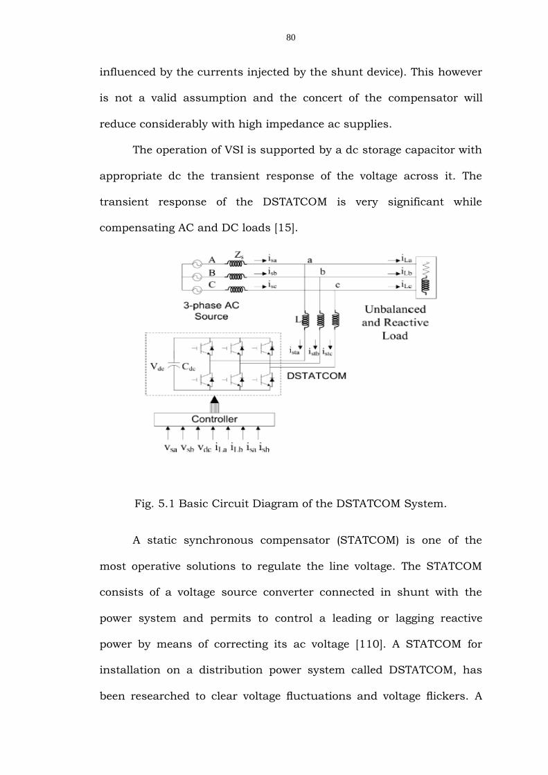
Fig. 5.1 Basic Circuit Diagram of the DSTATCOM System.
A static synchronous compensator (STATCOM) is one of the
most operative solutions to regulate the line voltage. The STATCOM
consists of a voltage source converter connected in shunt with the
power system and permits to control a leading or lagging reactive
power by means of correcting its ac voltage [110]. A STATCOM for
installation on a distribution power system called DSTATCOM, has
been researched to clear voltage fluctuations and voltage flickers. A
81
shunt active filter intended for installation on a power distribution
system, with emphasis on voltage regulation capability. Theoretical
investigation as well as computer simulation provides the dynamic
performance of harmonic damping and voltage regulation. As a result,
harmonic damping has the capability to improve the stability of
voltage regulation.
Thus, modification of the feedback gains makes it possible to
decrease voltage fluctuation in transient states, when the active filter
has the function of combined harmonic damping and voltage
regulation. The simulation results are shown to verify the effectiveness
of the active filter capable of both harmonic damping and voltage
regulation [84].
5.3. CONTROL STRATEGIES
For the controlling of voltage source converter and DC Link
voltage, different types of controllers are included to control the main
module.
5.3.1. Harmonic Damping
There are several methods to extract the harmonic components
from the detected three-phase waveforms. Among them, the so-called
p - q theory based on time domain has been widely applied to the
harmonic extraction circuit of active filters [15]. The detected three-
phase voltage is transformed into the D – Q coordinates as shown in
82
Fig.5.2. Two first order digital high pass filters (HPFs) with the same
cut off frequency as 20 Hz extract the dc component Vhd*, Vhq
* and V0
which corresponds to the fundamental frequency in the coordinates.
Fig. 5.2 Block Diagram of the control circuit equipped with the
Function of voltage regulation and Harmonic Damping.
5.3.2. Voltage Regulation
In line voltage regulation part is performed by a feedback
control. Two co ordinates Vd and Vq is compared with harmonic
extracted voltage *
hdV and *
hqV . A gain KV amplifies and to produce
current references for harmonic damping Ihd, Ihq and I0 as given in
(5.1), (5.2) and (5.3). The current reference for the voltage source
inverter is the sum of the current references from the three parts, as
follows:
83
)()()( ***
dcdcdhdhVcd VVVVGKsI (5.1)
)()( **
qhqhVcq VVGKsI (5.2)
)(3
1)(*
cbao VVVsI (5.3)
The obtained current reference is converted three phase current
reference by inverse D – Q transformation*
caI , *
cbI and*
ccI . The
three phase reference compensating current is compared with the
active filter compensating current extracted from ac system. Thus
three phase compensating current Ica, Icb and Icc are produced. The
obtained reference current is given to a PWM scheme, which is used to
generate controlled gate signal for shunt active filter.
5.3.3. DC Bus Voltage Control and PWM Method
A critical issue in this hybrid active filter is the dc-bus voltage
control. The dc bus consists of a single capacitor charged from the
power supply. During operation, the active filter may absorb an
amount of active power into or release it from the dc capacitor.
Excessive active power absorption will increase the dc-bus voltage,
and may damage the active filter.
The strategy used to control the dc-bus voltage is based on
active power control. According to the D– Q theory, a dc component in
the D–Q coordinates corresponds to active power. No direct axis
84
current on the D–Q coordinates flows in the LC filter. Thus, the active
power is controlled by adjusting the quadrature axis component.
The direct axis is set to zero. Fig. 5.3 shows a block diagram for
the dc bus voltage control. The DC bus voltage is detected and
compared with a reference, amplifying the error signal by a control
gain of 0.12. A limiter is included in the dc-bus control loop. It is
designed to ensure a smooth transient response and to avoid sudden
increments or decrements in the dc-bus voltage.
It is also designed to prevent the control loop from numerical
saturation in the control signals. A DC bus controller is required to
regulate the DC bus voltage Vdc and to compensate the inverter losses
as shown in Fig. 5.2. The measured DC bus voltage Vdc of each phase
is compared with its reference value Vdc*. Similarly, the remaining
phases and added all the error signals. The resulting error is applied
to a PI regulator.
The proportional and integral gains are set to 0.12 Ω-1 and
0.008Ω-1 s-1 respectively. Moreover, the DSTATCOM can build up and
regulate the DC capacitor voltage, the electrical quantity to be
controlled in the dc-voltage feedback loop is )( *
dcdc VV .The limiter
is set to ± 2.5 V in the digital controller which corresponds to 25% of
the maximum control signal. For a 200-V dc-bus voltage, the
maximum dc-bus control signal corresponds to a ± 10 V peak-to-peak
fundamental voltage for the inverter. The PWM gate pulses for
DSTATCOM are generated by using PWM method.
85
5.4. DC LINK VOLTAGE CONTROLLERS
The source supplies an unbalanced nonlinear ac load and a dc
load through the DC Link of the DSTATCOM, as shown in Fig. 5.1.
Due to transients on the load side, the dc bus voltage is significantly
affected. Any change in load directly affects the dc-link voltage. The
sudden removal of load would result in an increase dc-link voltage
above the reference value. The sudden increase of load would result in
reduce the dc-link voltage below the reference voltage. To regulate this
dc-link voltage, closed-loop controllers are used. The proportional-
integral-derivative (PID) control provides a generic and efficient
solution to many control problems. PID controller produces an output
signal consisting of three terms one proportional to the error signal,
another one proportional to the integral of error signal and the third
one proportional to the derivative of error signal. The control signal
from PID controller to regulate DC Link voltage is expressed in (5.4).
dtvVdKdtvVKvVKu dcdcrefddcdcrefidcdcrefpc
(5.4)
The proportional term provides overall control action
proportional to the error signal. An increase in proportional controller
gain reduces rise time and steady-state error but increases the
overshoot and settling time. An increase in integral gain reduces
steady state error but increases overshoot and settling time.
Increasing derivative gain will lead to improved stability.
86
5.4.1. Conventional DC Link voltage controller
Conventional PI Controller is used to maintain the DC Link
voltage at the reference value. To maintain the dc-link voltage at the
reference at the reference value, the DC Link capacitor needs a certain
amount of real power which is proportional to the difference between
the actual and reference voltages .The power required by the capacitor
can be expressed as
dtvVKvVKP dcdcrefidcdcrefpdc (5.5)
The dc-link capacitor has slow dynamics when compared to
the compensator. The drawback of this conventional controller is that
its transient response is slow, especially for fast-changing loads.
Also, the design of PI Controller parameters is quite difficult for
a complex system and hence these parameters are chosen by trial and
error. The disadvantage of the conventional PI Controller is the
transient response of this controller is very slow. Some work related to
the DC Link voltage controller and their stability is reported in [102].
Fig. 5.3 Conventional DC Link Voltage PI Controller.
87
5.4.2. Fast Acting DC Link Voltage Controller
In this an energy based DC Link voltage controller is proposed.
The energy required by the DC Link capacitor to charge from actual
value to the reference value can be computed as
dcdcrefdcdc vVCW 2
2
1 (5.6)
In general, the dc-link capacitor voltage has ripples with double
frequency with that of the supply frequency. The dc power required by
the dc capacitor can be computed as;
22'
2
1dcdcref
cc
dcdc vV
TT
WP (5.7)
However due to the lack of integral term there is steady state
error while compensating ac and dc loads. This is eliminated by
including integral term. The input this controller is error between the
squares of reference and actual capacitor voltages [96]. The controller
is shown in Fig. 5.4.
Fig. 5.4 Fast Acting DC Link Voltage based PI Controller.
88
An energy based controller it gives fast response compared to
the conventional PI Controller. The total power required by the DC
Link capacitor can be computed as;
dtvVKvVKP dcdcrefiedcdcrefpedc 2222 (5.8)
The transient response of the fast acting dc-link voltage
controller is very fast when compared to that of the conventional DC
Link voltage controller. By using Fuzzy Logic Controller instead of PI
Controller we will get the better result.
5.4.3. Fuzzy Logic Controller
Fuzzy control is a control method based on fuzzy logic. Just as
fuzzy logic can be described as “computing with words rather than
numbers. Fuzzy control can be simply described as “control with
sentence rather than equations”. Controllers based on fuzzy logic give
the linguistic strategies control conversion from expert knowledge in
automatic control strategies [52]. The development of control system
based on fuzzy logic involves the following steps:
a. Fuzzification strategy
b. Knowledge base
c. Rule base elaboration
d. Fuzzy inference
e. Defuzziffication strategy.
89
In addition, design of Fuzzy Logic Controller can provide
desirable both small signal and large signal dynamic performance at
same time, which is not possible with linear control technique. The
development of fuzzy logic approach here is limited to the design and
structure of the controller. Here the input is voltage and its variations;
the output constrain as the refI . The inputs of FLC are defined as the
voltage error and change of error.
The fuzzy controller ran with the input and output normalized
universe (-1,1). Fuzzy sets are defined for each input and out put
variable. There are seven fuzzy levels [NL-negative large, NM-negative
medium, NS-negative small Z-zero, PS-positive small, PM-positive
medium, PL-positive large) the membership functions for input and
output variables are triangular.
The min-max method interface engine is used. The fuzzy
method used in this FLC is center of area. The complete set of control
rules is shown in Table 5.1. Each of the 49 control rules represents
the desired controller response to a particular situation. The block
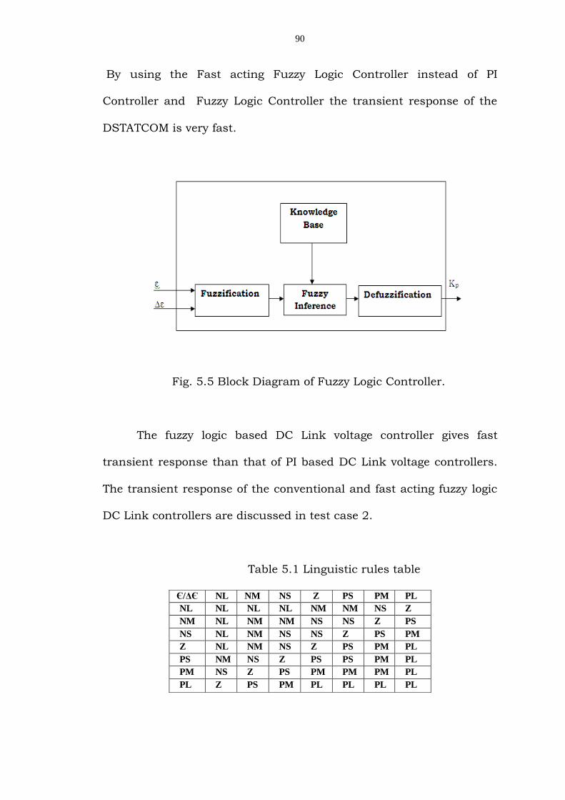
diagram presented in Fig. 5.5 shows a Fuzzy Logic Controller. The
simulation parameters are shown in Table 5.2. In this work to control
the DC Link voltage following controllers are used.
1. PI Controller
2. Fuzzy Logic Controller
3. Fast acting Fuzzy Logic Controller
90
By using the Fast acting Fuzzy Logic Controller instead of PI
Controller and Fuzzy Logic Controller the transient response of the
DSTATCOM is very fast.
Fig. 5.5 Block Diagram of Fuzzy Logic Controller.
The fuzzy logic based DC Link voltage controller gives fast
transient response than that of PI based DC Link voltage controllers.
The transient response of the conventional and fast acting fuzzy logic
DC Link controllers are discussed in test case 2.
Table 5.1 Linguistic rules table
Є/ΔЄ NL NM NS Z PS PM PL
NL NL NL NL NM NM NS Z
NM NL NM NM NS NS Z PS
NS NL NM NS NS Z PS PM
Z NL NM NS Z PS PM PL
PS NM NS Z PS PS PM PL
PM NS Z PS PM PM PM PL
PL Z PS PM PL PL PL PL
91
5.5. SIMULATION OF DSTATCOM WITH PI CONTROLLER
AND FUZZY LOGIC CONTROLLER
Computer simulation has become a crucial part of the power
electronics design procedure. DSTATCOM is a complex power
electronics device and the analysis of its behavior, which leads to
improved understanding, would be very difficult without computer
simulations (if possible at all).
The overall design process can be shortened through the use of
computer simulations, since it is usually easier to study the influence
of a parameter on the system behavior in simulation. The dynamic
and steady-state performance of DSTATCOM is observed for two
typical case studies.
In test case 1 Voltage Regulation and Harmonic Suppression of
Transformerless based DSTATCOM and in test case 2 Transient
response of the PI & Fuzzy Logic DC Link voltage controller of 3-phase
DSTATCOM while compensating AC & DC Loads the results of voltage
and current waveforms are presented below.
5.5.1. Voltage Regulation and Harmonic Suppression of
Transformerless Based DSTATCOM
Table 5.2 shows the circuit parameters used in the DSTATCOM
(shunt active filter). The simulation is carried for distribution system
92
with and without shunt active filter. Total harmonic distortion is
calculated for the system voltage and current.
Table 5.2 Circuit parameters used for the DSTATCOM.
Source voltage Va = Vb = Vc 1000 V
Power P 20KVA
Frequency F 50 Hz
Line inductance La = Lb = Lc 22.7 mH
DC - Capacitor C 4700µF
DC - voltage Vdc ref 200V
Load Diode
Rectifier & R
10Ω
Table 5.3 shows the THD for with and without shunt active
filter. From the Table 5.3, THD for with shunt active filter is very low
compared to without filter. In Fig. 5.8 shows the three phase voltages
of distribution system without shunt active filter. It can be seen that
the harmonic is disturbed in voltages. In Fig. 5.9 shows the three
phase voltages of distribution system with DSTATCOM. It could be
found that the wave shapes of the voltages are pure sinusoidal form.
Fig. 5.6 Main system without DSTATCOM.
93
Fig. 5.7 Main system with DSTATCOM.
Table 5.3 Comparison of Total harmonic distortion.
Parameters
THD for Source
current Is
THD for Load
Voltage VL
Isa Isb Isc Va Vb Vc
Without shunt
active filter
16%
18
%
17% 25% 25% 25%
With shunt
active filter
3.16% 3% 3% 4% 4% 4%
.
94
Fig. 5.8 Three Phase Voltages of Distribution System without
DSTATCOM.
Fig. 5.10 shows the three phase source current of distribution system
without shunt active filter. It can be seen that wave shapes are non
sinusoidal (the harmonic is affected in the source currents). Fig. 5.9
shows the three phase source current of distribution system with
shunt active filter. It can be seen that wave shapes are almost nearly
sinusoidal (the harmonic is suppressed in the source currents).
Fig. 5.9 Three Phase Voltages of Distribution System with
DSTATCOM.
95
Fig. 5.10 Three Phase Source Currents of Distribution System
with out DSTATCOM.
Fig. 5.11 Three Phase Source Currents of Distribution System with
DSTATCOM.
96
Fig. 5.12 Compensating Currents with DSTATCOM.
Fig. 5.12 shows the three phases compensated currents for shunt
active filter. In Fig. 5.13 shows the constant and small ripple dc
capacitor voltage of shunt active filter without startup-transient
overshoot.
Fig. 5.13 DC Voltage of DSTATCOM.
97
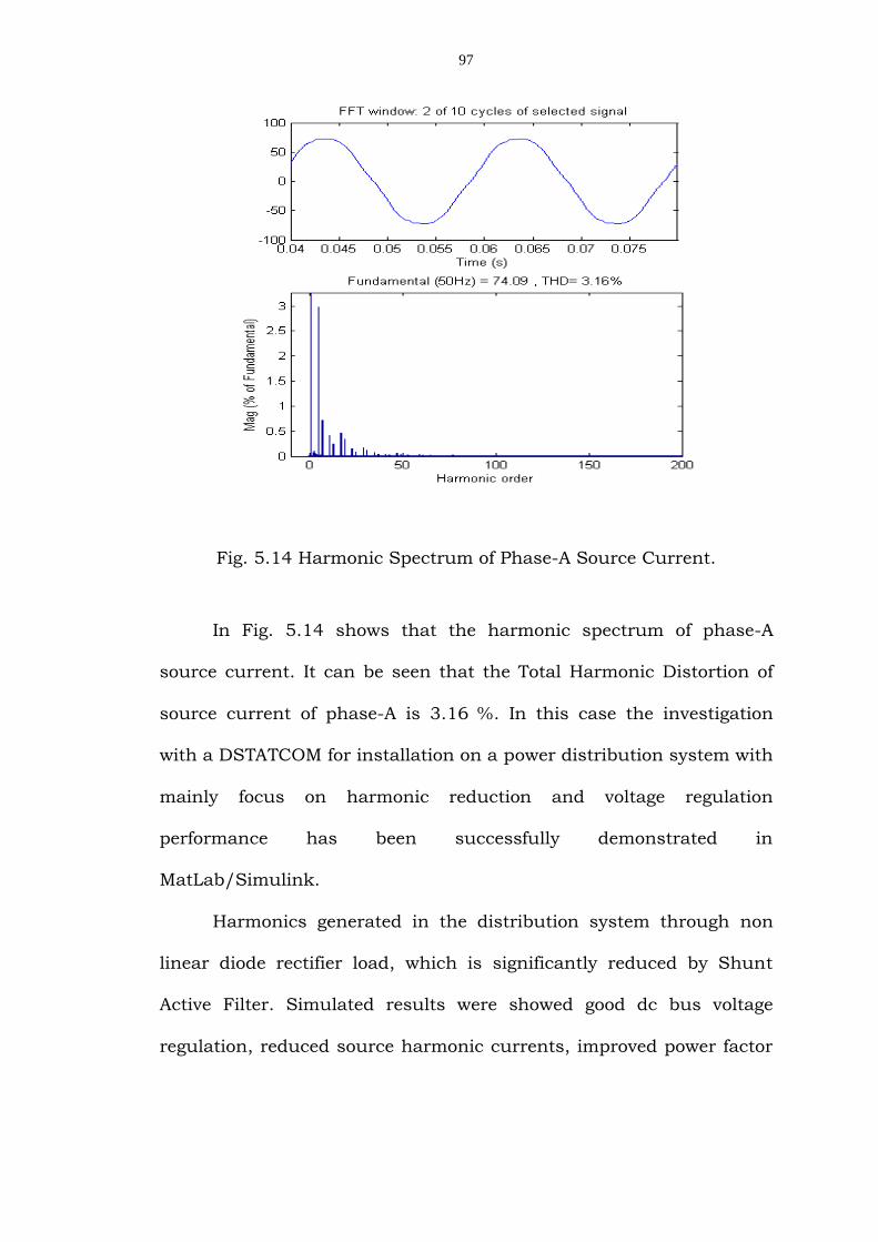
Fig. 5.14 Harmonic Spectrum of Phase-A Source Current.
In Fig. 5.14 shows that the harmonic spectrum of phase-A
source current. It can be seen that the Total Harmonic Distortion of
source current of phase-A is 3.16 %. In this case the investigation
with a DSTATCOM for installation on a power distribution system with
mainly focus on harmonic reduction and voltage regulation
performance has been successfully demonstrated in
MatLab/Simulink.
Harmonics generated in the distribution system through non
linear diode rectifier load, which is significantly reduced by Shunt
Active Filter. Simulated results were showed good dc bus voltage
regulation, reduced source harmonic currents, improved power factor
98
and stable operation. In future, intelligent control scheme is developed
to study the proposed system.
5.5.2. Transient Response of the PI & Fuzzy Logic DC-Link
Voltage Controller of 3-Phase DSTATCOM
By using MATLAB/Simulink the load compensator with VSI is
realized. The ac load consists of three-phase unbalanced load and
universal bridge. The system parameters and compensator parameters
are given in Table 5.4. Simulink diagrams of main system without and
with DSTATCOM are shown in Fig.5.15 and Fig.5.16 respectively. The
simulation studies of all the DC Link voltage controllers are analyzed.
Table 5.4 Simulation parameters for DSTATCOM
System parameters
Values
Supply voltage 400V,50 HZ
Unbalanced loads az =25, bz =44+j25.5, cz =50+j86.6
Nonlinear load Universal bridge
DC load dcR =100
DC capacitor dcC =30e-6
Reference dc-link voltage
refV =700
Gains of conventional DC-
link voltage controller
pK =40, Ki =20
Gains of fast acting dc-link
voltage controller
peK =0.11, ieK =0.055
5.5.2.1. Transient Response of the Conventional DC-Link
Voltage Controller
The transient response of the compensator is shown in Fig.
5.22. The total load which is combination of unbalanced and
99
nonlinear load is halved at the instant of t = 0.4s. Due to the sudden
decrease of the load the DC Link voltage is suddenly increase.
Therefore there is an increase in DC Link capacitor voltage above the
reference value.
Fig. 5.15 Main system without DSTATCOM.
The DC Link capacitor voltage is brought back to the reference
value based on the values of PI Controller gains after at t = 0.44s as
shown in Fig. 5.18. At 0.8s the capacitor produces power to the load
and the DC Link voltage is suddenly decrease below the reference
value.
So, the DC Link voltage is suddenly increases by removal of the
load and suddenly decreases by increasing the load. The capacitor
voltage is brought back to the reference value at t = 0.84s due to the
PI Controller action. Transient response of the conventional DC Link
voltage controller is very slow as shown in the Fig. 5.22.
100
Fig. 5.16 Main system with DSTATCOM.
Fig. 5.17 (a) Source Voltage, Fig. 5.17 (b) Source Current
Fig. 5.17 Source Voltage and Current.
101
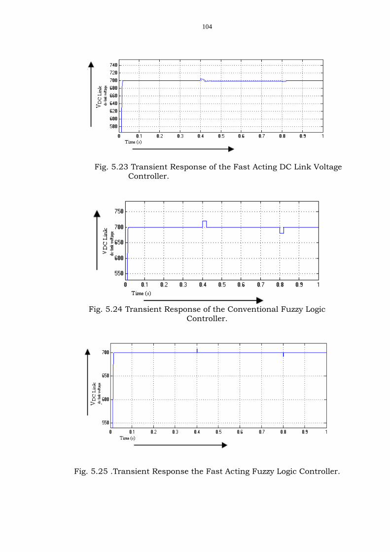
5.5.2.2. Transient performance of the Fast-Acting DC-Link
Voltage Controller
Transients in the load are considered the same as in the above
simulation study. At t = 0.4s the load is suddenly decrease and the
DC Link voltage is suddenly increased above the reference value and it
is brought back to its reference value based on the values of the PI
Controller gains. The fast acting DC Link voltage controller takes place
at the next instant and it is brought back to its reference value at t =
0.42s as shown in the Fig. 5.23. At t = 0.8s the capacitor produces
power to the load and the DC Link voltage is suddenly decrease below
the reference value. The fast acting DC Link voltage controller takes
place and the DC Link voltage is brought back to the reference value
at t = 0.82s as shown in the Fig. 5.23.
Fig. 5.18 DSTATCOM with PI Controller.
102
5.5.2.3. Transient Response of the Conventional Fuzzy Logic
Controller
By using the Fuzzy Logic Controller instead of the PI Controller
gives better transient response. The load is halved at t = 0.4s. So the
DC Link voltage is suddenly increased above the reference value. And
it is brought back to its reference value due to the Fuzzy Logic
Controller action at the instant of t = 0.42s as shown in the Fig. 5.24
and when the load is switched back to the full load at instant t = 0.8s,
the dc capacitor supplies power to the load. Hence DC Link voltage is
falls below the reference value and it is brought back to the reference