106
Chapter 5 - Internal Memory Luis Tarrataca [email protected] CEFET-RJ Luis Tarrataca Chapter 5 - Internal Memory 1 / 106

Chapter 5 - Internal Memory
Luis Tarrataca
CEFET-RJ
Luis Tarrataca Chapter 5 - Internal Memory 1 / 106

Table of Contents I
1 Introduction
2 Semiconductor Main Memory
Timing Waveforms
Major types of semiconductor memory
Random-access memory
Dynamic RAM (DRAM)
Static RAM (SRAM)
DRAM vs SRAM
Read-only memory (ROM)
Chip Logic
Luis Tarrataca Chapter 5 - Internal Memory 2 / 106

Table of Contents II
3 Error Correction
Hamming code
4 Advanced DRAM organization
Synchronous DRAM (SDRAM)
Double Data Rate SDRAM (DDR-SDRAM)
Graphics Double Data Rate SDRAM (GDDR-SDRAM)
High Bandwidth Memory (HBM)
5 References
Luis Tarrataca Chapter 5 - Internal Memory 3 / 106

Introduction
Introduction
Previous chapter discussed memory. This chapter presents:
• semiconductor main memory subsystems.
• ROM;
• DRAM;
• SRAM memories
• error control techniques used to enhance memory reliability
• more advanced DRAM architectures;
Luis Tarrataca Chapter 5 - Internal Memory 4 / 106

Introduction
But why do we need these types of memories? Any ideas?
Luis Tarrataca Chapter 5 - Internal Memory 5 / 106

Introduction
But why do we need these types of memories? Any ideas?
• Remember these guys?
Luis Tarrataca Chapter 5 - Internal Memory 6 / 106

Introduction
But why do we need these types of memories? Any ideas?
• Remember these guys?
• Serial memory takes different lengths of time to access information:
• depends on where the desired location is relative to the current position;
Luis Tarrataca Chapter 5 - Internal Memory 7 / 106

Semiconductor Main Memory
Semiconductor Main Memory
Memory is a collection of cells with the following properties
• They exhibit two stable states, used to represent binary 1 and 0;
• They are capable of being written into (at least once), to set the state;
• They are capable of being read to sense the state;
• Access time is the same regardless of the location;
Luis Tarrataca Chapter 5 - Internal Memory 8 / 106

Semiconductor Main Memory
Cell has three terminals capable of carrying an electrical signal:
• select: selects a memory cell for a read / write operation;
• control: indicates whether a read / write operation is being performed;
• read/write:
• For writing, terminal sets the state of the cell to 1 or 0.
• For reading, terminal is used for output of the cell’s state.
Figure: Memory cell write operation (Source:
[Stallings, 2015])
Figure: Memory cell read operation (Source:
[Stallings, 2015])
Luis Tarrataca Chapter 5 - Internal Memory 9 / 106

Semiconductor Main Memory
Example
Consider, a memory with a capacity of 1K words of 16 bits each:
• Capacity:
• 1K × 16 = 16Kbits =2Kbytes;
• Each word has an address:
• 0 to 1023
• When a word is read or written:
• memory acts on all 16 bits; Figure: Contents of a 1024 x 16 memory (Source:
[Mano and Kime, 2007])
Luis Tarrataca Chapter 5 - Internal Memory 10 / 106

Semiconductor Main Memory
Based on these concepts how do you think a write operation works? Any
ideas?
Luis Tarrataca Chapter 5 - Internal Memory 11 / 106

Semiconductor Main Memory
Write operation steps:
1 Apply the binary address of the desired word to the address lines.
2 Apply the data bits that must be stored in memory to the data input lines.
3 Activate the Write control line.
Memory unit will then transfer the bits to that address.
Luis Tarrataca Chapter 5 - Internal Memory 12 / 106

Semiconductor Main Memory
Based on these concepts how do you think a read operation works? Any
ideas?
Luis Tarrataca Chapter 5 - Internal Memory 13 / 106

Semiconductor Main Memory
Read operation steps:
1 Apply the binary address of the desired word to the address lines.
2 Activate the Read control line.
3 Memory unit will then transfer the bits to the data output lines.
Luis Tarrataca Chapter 5 - Internal Memory 14 / 106

Semiconductor Main Memory Timing Waveforms
Timing Waveforms
Memory unit operation is controlled by an external device (1/2):
• CPU is synchronized by its own clock pulses;
• Control signals are employed for memory read / write.
• Access time - time required for specifying an address and obtaining the
word;
• Write time - time required for specifying an address and storing the word;
• CPU must provide the control signals
Luis Tarrataca Chapter 5 - Internal Memory 15 / 106
Semiconductor Main Memory Timing Waveforms
Memory unit operation is controlled by an external device (2/2):
• CPU provides the control signals synchronized with its clock:
• This implies that:
• read / write operations will take a certain number of clock periods;
• What does this mean? Lets see with an example =)
Luis Tarrataca Chapter 5 - Internal Memory 16 / 106

Semiconductor Main Memory Timing Waveforms
Example (1/7)
Assume:
• CPU with a clock frequency of 50 Mhz;
• Memory access time: 65ns;
• Memory write time: 75ns
How many clock pulses do we need for read / write operations?
Luis Tarrataca Chapter 5 - Internal Memory 17 / 106
Semiconductor Main Memory Timing Waveforms
Example (2/7)
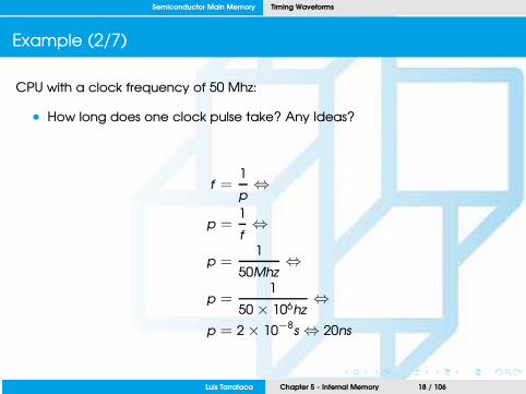
CPU with a clock frequency of 50 Mhz:
• How long does one clock pulse take? Any Ideas?
f =1
p⇔
p =1
f⇔
p =1
50Mhz⇔
p =1
50 × 106hz⇔
p = 2 × 10⁻⁸
s ⇔ 20ns
Luis Tarrataca Chapter 5 - Internal Memory 18 / 106

Semiconductor Main Memory Timing Waveforms
Example (3/7)
• CPU clock pulse: 20ns;
• Assume:
• Memory access time: 65ns;
• Memory write time: 75ns
How many clock pulses do we need for read / write operations?
• 4 clock pulses for read / write operations;
Luis Tarrataca Chapter 5 - Internal Memory 19 / 106

Semiconductor Main Memory Timing Waveforms
Example (4/7)
For the write operation:
Figure: Write cycle (Source: [Mano and Kime, 2007])
Luis Tarrataca Chapter 5 - Internal Memory 20 / 106

Semiconductor Main Memory Timing Waveforms
Example (5/7)
For the write operation:
1 CPU must provide the address (T1 pulse);
2 Memory enable is set (T1 pulse);
3 Data is supplied (T2 pulse);
4 Read/Write signal set to 0 for write operation (T2 pulse):
• CPU waits for T2 to let the address signals stabilize:
• Otherwise: wrong address may be used!
• Signal must stay activated long enough for the operation to finish;
5 When T4 completes, write operation has ended with 5ns to spare
Luis Tarrataca Chapter 5 - Internal Memory 21 / 106

Semiconductor Main Memory Timing Waveforms
Example (6/7)
For the read operation:
Figure: Read cycle (Source: [Mano and Kime, 2007])
Luis Tarrataca Chapter 5 - Internal Memory 22 / 106
Semiconductor Main Memory Timing Waveforms
Example (7/7)
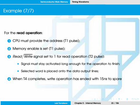
For the read operation:
1 CPU must provide the address (T1 pulse);
2 Memory enable is set (T1 pulse);
3 Read/Write signal set to 1 for read operation (T2 pulse):
• Signal must stay activated long enough for the operation to finish;
• Selected word is placed onto the data output lines;
4 When T4 completes, write operation has ended with 15ns to spare
Luis Tarrataca Chapter 5 - Internal Memory 23 / 106

Semiconductor Main Memory Major types of semiconductor memory
Major types of semiconductor memory
Lets have a look at the different types of memory technlogies:
Figure: Semiconductor memory types (Source: [Stallings, 2015])
Luis Tarrataca Chapter 5 - Internal Memory 24 / 106

Semiconductor Main Memory Random-access memory
Random-access memory
• Randomly access any possible address;
• Possible both to read and write data;
• Volatile: requires a power supply;
• For a chip with m words with n bits per word:
• Consists of an array with m × n binary storage cells
• E.g.: DRAM and SRAM.
• Lets have a look at these =)
Luis Tarrataca Chapter 5 - Internal Memory 25 / 106

Semiconductor Main Memory Random-access memory
Dynamic RAM (DRAM)
Made with cells that store data as charge on capacitors:
• Capacitor charge presence or absence is interpreted as a binary 1 or 0;
• Capacitors have a natural tendency to discharge;
• Requires periodic charge refreshing to maintain data storage
Luis Tarrataca Chapter 5 - Internal Memory 26 / 106

Semiconductor Main Memory Random-access memory
DRAM Cell components:
If voltage goes to the address line:
• Transistor closes:
• Current flows to capacitor;
If no voltage goes to the address line:
• Transistor opens:
• No current flows to capacitor;
Figure: DRAM Cell (Source: [Stallings, 2015])
Luis Tarrataca Chapter 5 - Internal Memory 27 / 106

Semiconductor Main Memory Random-access memory
Based on the DRAM cell components:
How do you think a write operation works? Any ideas?
Figure: DRAM Cell (Source: [Stallings, 2015])
Luis Tarrataca Chapter 5 - Internal Memory 28 / 106

Semiconductor Main Memory Random-access memory
Write operation:
1 Voltage signal is applied to the bit line
• Low voltage = 0;
• High voltage = 1;
2 A signal is then applied to the address line:
• transistor closes...
• ...charge goes to the capacitor.
Figure: DRAM Cell (Source: [Stallings, 2015])
Luis Tarrataca Chapter 5 - Internal Memory 29 / 106

Semiconductor Main Memory Random-access memory
Based on the DRAM cell components:
How do you think a read operation works? Any ideas?
Figure: DRAM Cell (Source: [Stallings, 2015])
Luis Tarrataca Chapter 5 - Internal Memory 30 / 106

Semiconductor Main Memory Random-access memory
Read operation:
1 Address line is activated
2 Transistor turns on
3 Capacitor charge goes to bit line...;
• ...Low voltage = 0
• ...High voltage = 1
4 Cell readout discharges the capacitor:
• state must be restored;
Figure: Dynamic RAM Cell (Source:
[Stallings, 2015])
Luis Tarrataca Chapter 5 - Internal Memory 31 / 106

Semiconductor Main Memory Random-access memory
Besides DRAM...
Do you have any idea of other type of technology that can be employed?
Any ideas?
• Maybe based on something that we saw earlier in the semester...
Luis Tarrataca Chapter 5 - Internal Memory 32 / 106

Semiconductor Main Memory Random-access memory
Static RAM (SRAM)
Binary values are stored using SR flip-flop configurations:
• Remember flip-flops? We saw them at the beginning of the semester...
• Same logic elements used in the processor registers;
• will hold its data as long as power is supplied to it.
Luis Tarrataca Chapter 5 - Internal Memory 33 / 106

Semiconductor Main Memory Random-access memory
Cell storage is modelled by an SR flip-flop:
Figure: SRAM Cell (Source:
[Mano and Kime, 2007]) Figure: SR Flip flop table (Source: [Stallings, 2015])
• Flip-flop inputs are enabled by a select (S) signal:
• S = 0, stored content is held;
• S = 1, stored content is determined by B and B
• Flip-flop outputs are enabled by a select (S) signal:
• S = 0, both C and C are 0;
• S = 1, C is the stored value and C is its complement.
Luis Tarrataca Chapter 5 - Internal Memory 34 / 106

Semiconductor Main Memory Random-access memory
How to choose between DRAM and SRAM? Any ideas?
• What are the pros / cons of DRAM?
• What are the pros / cons of SRAM?
Luis Tarrataca Chapter 5 - Internal Memory 35 / 106

Semiconductor Main Memory DRAM vs SRAM
DRAM vs SRAM (1/5)
• Both are volatile:
• power must be continuously supplied to preserve the bit values;
• DRAMs:
• Periodically refresh capacitor’s charge;
• SRAM:
• No need to periodically refresh;
Luis Tarrataca Chapter 5 - Internal Memory 36 / 106

Semiconductor Main Memory DRAM vs SRAM
DRAM vs SRAM (2/5)
• DRAM cell is simpler and smaller than a SRAM cell:
• (1 transistor, 1 capacitor) vs. SR flip-flop
• DRAM is denser (smaller cells = more cells per unit area) ;
• Due to its simplicity:
• DRAM is cheaper than corresponding SRAM;
Luis Tarrataca Chapter 5 - Internal Memory 37 / 106

Semiconductor Main Memory DRAM vs SRAM
DRAM vs SRAM (3/5)
• DRAM requires the supporting refresh circuitry (readout):
• This is a fixed cost, does not increase with size =)
• This cost is more than compensated by the smaller cost of DRAM cells;
• Thus, DRAMs tend to be favoured for large memory requirements;
Luis Tarrataca Chapter 5 - Internal Memory 38 / 106

Semiconductor Main Memory DRAM vs SRAM
DRAM vs SRAM (4/5)
• SRAMs are faster and more expensive than DRAMs
• No need to refresh the circuitry after a readout;
• Because of these characteristics:
• DRAM: used in main memory;
• SRAM: used in cache;
Luis Tarrataca Chapter 5 - Internal Memory 39 / 106
Semiconductor Main Memory DRAM vs SRAM
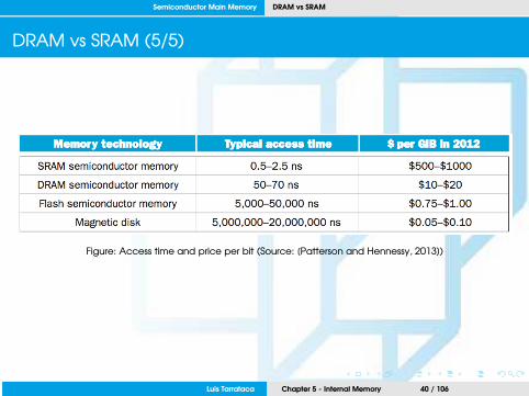
DRAM vs SRAM (5/5)
Figure: Access time and price per bit (Source: [Patterson and Hennessy, 2013])
Luis Tarrataca Chapter 5 - Internal Memory 40 / 106

Semiconductor Main Memory Read-only memory (ROM)
Read-only memory (ROM)
• Contains a permanent pattern of data that cannot be changed;
• Therefore:
• Possible to read a ROM;
• Not possible to write data more than once;
• Advantage:
• Data / Program is permanently in main memory;
• No need to load from a secondary storage device;
• Original BIOS were stored in ROM chips.
• Nonvolatile: no power source is required;
Luis Tarrataca Chapter 5 - Internal Memory 41 / 106

Semiconductor Main Memory Read-only memory (ROM)
Not possible to write data more than once:
• Data is wired into the chip as part of the fabrication process
• Data insertion is expensive;
• No room for error:
• If one bit is wrong, the whole batch of ROMs must be thrown out.
• =’(
Luis Tarrataca Chapter 5 - Internal Memory 42 / 106

Semiconductor Main Memory Read-only memory (ROM)
Different types of ROM (1/4):
• Programmable ROM (PROM):
• nonvolatile and may be written into only once;
• Writing may be performed at a later time than the original chip fabrication.
• Special equipment is required for the writing process;
• More expensive than ROM;
Luis Tarrataca Chapter 5 - Internal Memory 43 / 106

Semiconductor Main Memory Read-only memory (ROM)
Different types of ROM (2/4):
• Erasable programmable read-only memory (EPROM):
• Can be altered multiple times;
• Entire memory contents need to be erased;
• Special equipment is required for the erasure process:
• Ultra-violet radiation;
• Slow erasure procedure (>20 minutes);
• More expensive than PROM;
Luis Tarrataca Chapter 5 - Internal Memory 44 / 106

Semiconductor Main Memory Read-only memory (ROM)
Different types of ROM (3/4):
• Electrically erasable programmable read-only memory (EEPROM):
• Can be altered multiple times;
• Special equipment is required for the erasure process:
• No need to erase prior contents...
• ...only the byte or bytes addressed are updated.
• Ultra-violet radiation;
• Faster erasure procedure than EPROM;
• More expensive than EPROM;
Luis Tarrataca Chapter 5 - Internal Memory 45 / 106

Semiconductor Main Memory Read-only memory (ROM)
Different types of ROM (4/4):
• Flash memory:
• named because of the speed with which it can be reprogrammed;
• between EPROM and EEPROM in both cost and functionality:
• Uses an electrical erasing technology;
• Possible to erase blocks of memory;
• Does not provide byte-level erasure;
• Technology used in pendrives;
Luis Tarrataca Chapter 5 - Internal Memory 46 / 106

Semiconductor Main Memory Chip Logic
Chip Logic
Now that we have seen the core memory concepts:
How can we organize these concepts into a functional memory unit?
Any ideas?
Luis Tarrataca Chapter 5 - Internal Memory 47 / 106

Semiconductor Main Memory Chip Logic
Typical organization of a 16-Mbit DRAM:
Figure: Typical 16 Megabit DRAM (4M * 4) (Source: [Stallings, 2015])
Luis Tarrataca Chapter 5 - Internal Memory 48 / 106

Semiconductor Main Memory Chip Logic
In the case of the previous picture (1/4):
• 4 bits are read or written at a time
• Memory array is organized as four arrays of 2048 by 2048 elements;
• Address lines supply the address of the word to be selected;
• log2 W lines are needed;
• E.g.:, 11 address lines are needed to select one of 2048 rows;
• These lines are fed into a row decoder;
• Decoder activates a single single line of memory;
Luis Tarrataca Chapter 5 - Internal Memory 49 / 106

Semiconductor Main Memory Chip Logic
In the case of the previous picture (2/4):
• The same procedure is applied to select columns;
• Note that there are only 11 address lines (A0 − A10):
• Half the number you would expect for a 2048 × 2048 array.
• First, a row address select (RAS) signal is emitted:
• to define the row address of the array
• Second, a column address select (CAS) signal is emitted:
• to define the column address of the array
Luis Tarrataca Chapter 5 - Internal Memory 50 / 106

Semiconductor Main Memory Chip Logic
In the case of the previous picture (3/4):
• Write enable (WE) signal
• specifies that a write operation is to be performed;
• Output enable (OE)
• signal specifies that a read operation is to be performed;
Luis Tarrataca Chapter 5 - Internal Memory 51 / 106

Semiconductor Main Memory Chip Logic
In the case of the previous picture (4/4):
• Refreshing technique:
• Refresh counter: step through all of the row values;
• For each line:
• Memory row is chosen;
• RAS line is activated;
• Data are read out and written back into the same location
Luis Tarrataca Chapter 5 - Internal Memory 52 / 106

Semiconductor Main Memory Chip Logic
Lets look at a simplified example:
Figure: 256KByte memory organization (Source: [Stallings, 2015])
Luis Tarrataca Chapter 5 - Internal Memory 53 / 106

Semiconductor Main Memory Chip Logic
In the case of the previous picture:
• Shows a memory module consisting of 256K 8-bit words;
• For 256K words, an 18-bit address is needed
• Memory Address Register containing:
• 9 bits for line selection;
• 9 bits for column selection;
• Address is presented to 8 256K 1-bit chips:
• each of which provides the input/ output of 1 bit.
• Memory Buffer Register of 8-bits:
• Where data is read from;
• Where data is written to;
Luis Tarrataca Chapter 5 - Internal Memory 54 / 106

Semiconductor Main Memory Chip Logic
And that concludes the semiconductor memory section... Yay!!!
• Next topic please =)
Luis Tarrataca Chapter 5 - Internal Memory 55 / 106

Error Correction
Error Correction
Semiconductor memory systems are subject to errors (1/2):
Hard Failures: • Permanent physical defect;
• Damaged memory cell(s) cannot reliably store data:
• become stuck at 0 or 1 or...
• ...switch erratically between 0 and 1
• Caused by:
• Harsh environmental abuse;
• Manufacturing defects;
• Wear and tear;
Luis Tarrataca Chapter 5 - Internal Memory 56 / 106
Error Correction
Error Correction
Semiconductor memory systems are subject to errors (2/2):
Soft Failures: • Random, nondestructive event
• Alters the contents of one or more memory cells
• Without damaging the memory.
• Caused by:
• Power supply problems;
• Alpha particles (radioactive decay).
Luis Tarrataca Chapter 5 - Internal Memory 57 / 106

Error Correction
Hard and soft errors are clearly undesirable...
So what can we do to address them? Any ideas?
Luis Tarrataca Chapter 5 - Internal Memory 58 / 106

Error Correction
Hard and soft errors are clearly undesirable...
So what can we do to address them? Any ideas?
• Idea: algorithms for both detecting and correcting errors ;)
Luis Tarrataca Chapter 5 - Internal Memory 59 / 106

Error Correction
General method
Figure: Error correcting code function (Source: [Stallings, 2015])
Luis Tarrataca Chapter 5 - Internal Memory 60 / 106

Error Correction
From the previous picture (1/3):
1 M-bit data is to be written into memory;
2 Computation f(M) is performed on the data (K check bits);
3 Both the data and the code (M + K bits) are stored in memory;
Luis Tarrataca Chapter 5 - Internal Memory 61 / 106

Error Correction
From the previous picture (2/3):
4 Eventually, the stored word will be read out;
5 Computation f(M) is again performed on the data (K check bits);
6 A comparison is made between both check bits;
Luis Tarrataca Chapter 5 - Internal Memory 62 / 106

Error Correction
From the previous picture (3/3):
7 The comparison yields one of three results:
• No errors are detected:
• Fetched data bits are sent out;
• An error is detected, and it is possible to correct the error:
• Data bits plus error correction bits are fed into a corrector
• Producing a corrected set of M bits to be sent out.
• An error is detected, but it is not possible to correct it:
• =’( This condition is reported.
Luis Tarrataca Chapter 5 - Internal Memory 63 / 106

Error Correction
Guess what we will be seeing next?
Luis Tarrataca Chapter 5 - Internal Memory 64 / 106

Error Correction
Guess what we will be seeing next?
• Error-correcting codes =)
• High-probability of appearing in the next exam... ;)
• Lets start with a basic example...
Luis Tarrataca Chapter 5 - Internal Memory 65 / 106

Error Correction Hamming code
Hamming code
Simplest of the error-correcting codes:
Lets see an example on 4-bits:
1 Data = {1, 1, 1, 0}
2 Uses Venn diagrams;
3 Three intersecting circles → seven compartments;
4 We assign the 4 data bits to the inner compartments
Figure: Hamming error correcting
code (Source: [Stallings, 2015])
Luis Tarrataca Chapter 5 - Internal Memory 66 / 106

Error Correction Hamming code
Hamming code
Simplest of the error-correcting codes:
5 Other compartments filled with parity bits;
6 What is a parity bit?
• Total number of 1s in circle must be even;
7 Parity values:
• Circle A = three data 1s, parity bit is 1;
• Circle B = two data 1s, parity bit is 0;
• Circle C = two data 1s, parity bit is 0;Figure: Hamming error correcting
code (Source: [Stallings, 2015])
Luis Tarrataca Chapter 5 - Internal Memory 67 / 106

Error Correction Hamming code
Hamming code
Simplest of the error-correcting codes:
8 Imagine an error changes one of the data bits
• See new figure
9 Check parity bits:
• CA = two data 1s, parity bit is 1 should be 0;
• CB = two data 1s, parity bit is 0 should be 0;
• CC = one data 1s, parity bit is 0 should be 1;
10 Therefore:
• error: intersection of A with C, excluding BFigure: Hamming error correcting
code (Source: [Stallings, 2015])
Luis Tarrataca Chapter 5 - Internal Memory 68 / 106

Error Correction Hamming code
Hamming code
Simplest of the error-correcting codes:
11 Error can be corrected by changing that bit.
Figure: Hamming error correcting
code (Source: [Stallings, 2015])
Luis Tarrataca Chapter 5 - Internal Memory 69 / 106

Error Correction Hamming code
Ok, we saw an example for 4 bits...
How can we extend this to any number of bits?
Luis Tarrataca Chapter 5 - Internal Memory 70 / 106

Error Correction Hamming code
Example code to detect and correct single-bit errors in 8-bit words:
• Error code is calculated twice (check1 and check2) (Slide 60)
• Bit-by-bit comparison is done by performing XOR (⊕):
b7 b6 b5 b4 b3 b2 b1 b0
check1 0 0 1 1 0 0 1 1
check2 0 1 0 1 0 1 0 1
check1 ⊕ check2 0 1 1 0 0 1 1 0
• Result is called the syndrome word:
• A zero bit means a match;
• A one bit means a mismatch;
Luis Tarrataca Chapter 5 - Internal Memory 71 / 106

Error Correction Hamming code
Syndrome word will have K -bits
• Syndrome has a range between 0 and 2K − 1;
• If syndrome has value 0, no error was detected;
• Otherwise, 2K − 1 values to indicate which bit was in error;
Luis Tarrataca Chapter 5 - Internal Memory 72 / 106

Error Correction Hamming code
Syndrome word will have K -bits
• Syndrome has a range between 0 and 2K − 1;
• If syndrome has value 0, no error was detected;
• Otherwise, 2K − 1 values to indicate which bit was in error;
But how large should K be?
Luis Tarrataca Chapter 5 - Internal Memory 73 / 106

Error Correction Hamming code
But how large should K be?
• We know that there should exist:
• 2K − 1 combinations to indicate where the error is.
• Therefore, if we have M-bit words:
• 2K − 1 should be large enough to encode one of the M available positions;
• Error can be in position 0;
• Error can be in position 1;
• . . .
• Error can be in position M − 1;
• I.e.: 2K − 1 ≥ M;
Luis Tarrataca Chapter 5 - Internal Memory 74 / 106

Error Correction Hamming code
But what happens if we have an error in the K check bits?
Error can be:
• As before in one of the original M positions;
• But now we also need to consider K positions;
• I.e.: 2K − 1 ≥ M + K ;
Luis Tarrataca Chapter 5 - Internal Memory 75 / 106

Error Correction Hamming code
Figure: Increase in word length with error correction (Source: [Stallings, 2015])
• For 8 data bits, 4 check bits are required, representing an increase of 50%
• K = 3 : 23 − 1 < 8 + 3
• K = 4 : 24 − 1 ≥ 8 + 4
Luis Tarrataca Chapter 5 - Internal Memory 76 / 106

Error Correction Hamming code
We would like to generate a syndrome with the following characteristics:
• If the syndrome contains all 0s:
• No error has been detected.
• If the syndrome contains one and only one bit set to 1
• Then an error has occurred in one of the check bits
• No correction is needed;
• If the syndrome contains more than one bit set to 1:
• Then the syndrome value indicates the position of the data bit in error.
• This data bit is inverted for correction.
Luis Tarrataca Chapter 5 - Internal Memory 77 / 106

Error Correction Hamming code
Data (8-bit) and syndrome (4-bit) are arranged into a 12-bit word:
Figure: Layout of data bits and check bits (Source: [Stallings, 2015])
1 Bit positions that are powers of 2 are designated as check bits;
2 Bit positions that are not power of 2 are designated as data bits;
Luis Tarrataca Chapter 5 - Internal Memory 78 / 106

Error Correction Hamming code
3 Each check bit operates on every data bit whose position number:
• contains a 1 in the same bit position as the position number of that check bit.
4 E.g.: Check bit 1 operates on:
• Data bit 1 (0011), since it has a 1 in position 1;
• Data bit 2 (0101), since it has a 1 in position 1;
• Data bit 4 (0101), since it has a 1 in position 1;
• Data bit 5 (1001), since it has a 1 in position 1;
• Data bit 7 (1011), since it has a 1 in position 1;
5 I.e.: C1 = D1 ⊕ D2 ⊕ D4 ⊕ D5 ⊕ D7
Luis Tarrataca Chapter 5 - Internal Memory 79 / 106

Error Correction Hamming code
6 E.g.: Check bit 2 operates on:
• Data bit 1 (0011), since it has a 1 in position 2;
• Data bit 3 (0110), since it has a 1 in position 2;
• Data bit 4 (0111), since it has a 1 in position 2;
• Data bit 6 (1010), since it has a 1 in position 2;
• Data bit 7 (1011), since it has a 1 in position 2;
7 I.e.: C2 = D1 ⊕ D3 ⊕ D4 ⊕ D6 ⊕ D7
Luis Tarrataca Chapter 5 - Internal Memory 80 / 106

Error Correction Hamming code
8 E.g.: Check bit 4 operates on:
• Data bit 2 (0101), since it has a 1 in position 3;
• Data bit 3 (0110), since it has a 1 in position 3;
• Data bit 4 (0111), since it has a 1 in position 3;
• Data bit 8 (1100), since it has a 1 in position 3;
9 I.e.: C4 = D2 ⊕ D3 ⊕ D4 ⊕ D8
Luis Tarrataca Chapter 5 - Internal Memory 81 / 106

Error Correction Hamming code
10 E.g.: Check bit 8 operates on:
• Data bit 5 (1001), since it has a 1 in position 4;
• Data bit 6 (1010), since it has a 1 in position 4;
• Data bit 7 (1011), since it has a 1 in position 4;
• Data bit 8 (1100), since it has a 1 in position 4;
11 I.e.: C8 = D5 ⊕ D6 ⊕ D7 ⊕ D8
Luis Tarrataca Chapter 5 - Internal Memory 82 / 106

Error Correction Hamming code
12 Overall conclusion:
C1 = D1 ⊕ D2 ⊕ D4 ⊕ D5 ⊕ D7
C2 = D1 ⊕ D3 ⊕ D4 ⊕ ⊕ D6 ⊕ D7
C4 = D2 ⊕ D3 ⊕ D4 ⊕ D8
C8 = D5 ⊕ D6 ⊕ D7 ⊕ D8
Luis Tarrataca Chapter 5 - Internal Memory 83 / 106

Error Correction Hamming code
Example (1/5)
Lets say that the 8-bit input word is 00111001:
Figure: Check bit calculation (Source: [Stallings, 2015])
• C1 = D1 ⊕ D2 ⊕ D4 ⊕ D5 ⊕ D7 = 1 ⊕ 0 ⊕ 1 ⊕ 1 ⊕ 0 = 1
• C2 = D1 ⊕ D3 ⊕ D4 ⊕ D6 ⊕ D7 = 1 ⊕ 0 ⊕ 1 ⊕ 1 ⊕ 0 = 1
• C4 = D2 ⊕ D3 ⊕ D4 ⊕ D8 = 0 ⊕ 0 ⊕ 1 ⊕ 0 = 1
• C8 = D5 ⊕ D6 ⊕ D7 ⊕ D8 = 1 ⊕ 1 ⊕ 0 ⊕ 0 = 0
Luis Tarrataca Chapter 5 - Internal Memory 84 / 106

Error Correction Hamming code
Example (2/5)
The combined data and check bits will be stored as:
Figure: Check bit calculation (Source: [Stallings, 2015])
Luis Tarrataca Chapter 5 - Internal Memory 85 / 106

Error Correction Hamming code
Example (3/5)
Suppose now that data bit 3 sustains an error and is changed from 0 to 1:
Figure: Check bit calculation (Source: [Stallings, 2015])
Luis Tarrataca Chapter 5 - Internal Memory 86 / 106

Error Correction Hamming code
Example (4/5)
Check bits are recalculated:
• C1 = D1 ⊕ D2 ⊕ D4 ⊕ D5 ⊕ D7 = 1 ⊕ 0 ⊕ 1 ⊕ 1 ⊕ 0 = 1
• C2 = D1 ⊕ D3 ⊕ D4 ⊕ D6 ⊕ D7 = 1 ⊕ 1 ⊕ 1 ⊕ 1 ⊕ 0 = 0
• C4 = D2 ⊕ D3 ⊕ D4 ⊕ D8 = 0 ⊕ 1 ⊕ 1 ⊕ 0 = 0
• C8 = D5 ⊕ D6 ⊕ D7 ⊕ D8 = 1 ⊕ 1 ⊕ 0 ⊕ 0 = 0
Luis Tarrataca Chapter 5 - Internal Memory 87 / 106

Error Correction Hamming code
Example (5/5)
Syndrome is formed by comparing new check bits against old:
C8 C4 C2 C1
0 1 1 1
⊕ 0 0 0 1
0 1 1 0
• The result is 0110 (bit position 6) indicates that data bit 3 is in error.
Figure: Check bit calculation (Source: [Stallings, 2015])
Luis Tarrataca Chapter 5 - Internal Memory 88 / 106

Error Correction Hamming code
Example 1
Fill out the table and calculate the syndrome for:
• Data stored: 11101001
• Data fetched: 01101001
Bit Position 12 11 10 9 8 7 6 5 4 3 2 1
Position Number 1100 1011 1010 1001 1000 0111 0110 0101 0100 0011 0010 0001
Data bit
Check bit
Word Stored as
Word Fetched as
Luis Tarrataca Chapter 5 - Internal Memory 89 / 106

Error Correction Hamming code
Example 2
Fill out the table and calculate the syndrome for:
• Data stored: 10011001
• Data fetched: 10010001
Bit Position 12 11 10 9 8 7 6 5 4 3 2 1
Position Number 1100 1011 1010 1001 1000 0111 0110 0101 0100 0011 0010 0001
Data bit
Check bit
Word Stored as
Word Fetched as
Luis Tarrataca Chapter 5 - Internal Memory 90 / 106

Advanced DRAM organization
Advanced DRAM organization
Basic building block of main memory remains the DRAM chip:
• No significant changes in DRAM architecture from the 1970s to the 2000’s
• Traditional DRAM chip is constrained both:
• by its internal architecture and...
• ...by its interface to the processor’s memory bus.
So, what can be done to improve performance?
Luis Tarrataca Chapter 5 - Internal Memory 91 / 106

Advanced DRAM organization
So, what can be done to improve performance?
• One or more levels of high-speed SRAM cache;
• However:
• SRAM is costlier than DRAM;
• Expanding cache size beyond a certain point yields diminishing returns;
• A number of enhancements have been developed:
• SDRAM;
• DDR-DRAM;
• RDRAM
Luis Tarrataca Chapter 5 - Internal Memory 92 / 106

Advanced DRAM organization
A performance comparison of the different types of DRAM:
Figure: Performance comparison of some DRAM alternatives (Source: [Stallings, 2015])
Luis Tarrataca Chapter 5 - Internal Memory 93 / 106

Advanced DRAM organization Synchronous DRAM (SDRAM)
Synchronous DRAM (SDRAM)
SDRAM works in a synchronous manner:
• Data exchanges with the processor are synchronized with system clock;
• Unlike DRAM which is asynchronous and imposes wait states;
Wait, what is a wait state?
Luis Tarrataca Chapter 5 - Internal Memory 94 / 106

Advanced DRAM organization Synchronous DRAM (SDRAM)
Wait, what is a wait state?
In a typical DRAM (1/2):
1 Processor presents addresses and control signals to the memory;
2 Indicating that data at an address should be read/written from/into;
3 After a delay (access time) the DRAM either writes or reads the data:
Luis Tarrataca Chapter 5 - Internal Memory 95 / 106

Advanced DRAM organization Synchronous DRAM (SDRAM)
Wait, what is a wait state?
In a typical DRAM (2/2):
4 During the access-time delay DRAM performs various tasks, e.g.:
• Activating high capacitance of the row and column lines;
• Sensing the data;
• Routing data out through the output buffers
5 Processor waits through this delay, slowing performance.
• Thus the name wait states
Luis Tarrataca Chapter 5 - Internal Memory 96 / 106

Advanced DRAM organization Synchronous DRAM (SDRAM)
Based on the previous text...
What do you think would be an ideal method for interacting with memory?
Any ideas?
Luis Tarrataca Chapter 5 - Internal Memory 97 / 106

Advanced DRAM organization Synchronous DRAM (SDRAM)
Based on the previous text...
What do you think would be an ideal method for interacting with memory?
Any ideas?
• Let the processor issue read / write commands;
• Memory processes these requests;
• Meanwhile the processor is able to do something else;
Luis Tarrataca Chapter 5 - Internal Memory 98 / 106

Advanced DRAM organization Synchronous DRAM (SDRAM)
SDRAM advantage 1
• Processor issues data and address information to the SDRAM;
• SDRAM responds after a set number of clock cycles;
• Meanwhile the processor can perform other tasks;
Figure: SDRAM read timing (Source: [Stallings, 2015])
• In this example:
• Processor issues read command (READ A);
• Memory has a latency of two clock cycles and 4-bits bursts;
• Meanwhile processor executes NOP instructions;
Luis Tarrataca Chapter 5 - Internal Memory 99 / 106

Advanced DRAM organization Synchronous DRAM (SDRAM)
SDRAM advantage 2
• Also, DRAM has the ability to transfer bits in burst:
• Several units of data are synchronously transferred onto the bus;
• Without having to specify the address of those data units;
• No need to refresh MAR multiple times;
• Can be done when reading multiple sequential addresses;
• Is performed by specifying a burst length variable;
Luis Tarrataca Chapter 5 - Internal Memory 100 / 106

Advanced DRAM organization Double Data Rate SDRAM (DDR-SDRAM)
Double Data Rate SDRAM (DDR-SDRAM)
Transfers are synchronized to the system clock:
• Same as SDRAM, however:
• SDRAM only transfers on the rising edge of the clock;
• DDR-SDRAM transfers on the rising and the falling edge of the clock:
• Twice the bandwidth based on the same clock rate and data width;
Luis Tarrataca Chapter 5 - Internal Memory 101 / 106

Advanced DRAM organization Double Data Rate SDRAM (DDR-SDRAM)
Figure: DDR SDRAM road timing (Source: [Stallings, 2015])
Luis Tarrataca Chapter 5 - Internal Memory 102 / 106

Advanced DRAM organization Graphics Double Data Rate SDRAM (GDDR-SDRAM)
Graphics Double Data Rate SDRAM (GDDR-SDRAM)
Sames as DDR-SDRAM, however:
• Lower voltage requirements, thus lower heat dissipation;
• Higher data width bus allows for higher transfer speeds;
• Made specifically for the texture requirements of video games;
Figure: Geforce GTX 1080 Figure: Geforce GTX 1080 Undercarriage
Luis Tarrataca Chapter 5 - Internal Memory 103 / 106

Advanced DRAM organization Graphics Double Data Rate SDRAM (GDDR-SDRAM)
What about the future? What is there to come?
Luis Tarrataca Chapter 5 - Internal Memory 104 / 106

Advanced DRAM organization High Bandwidth Memory (HBM)
High Bandwidth Memory (HBM)
• 3D-stacked DRAM, a.k.a. stack;
Figure: GDDR5 vs HBM (Source: [Stallings, 2015])
• Next generation of graphic cards;
Luis Tarrataca Chapter 5 - Internal Memory 105 / 106

References
References I
Mano, M. M. and Kime, C. (2007).
Logic and Computer Design Fundamentals.
Prentice Hall Press, Upper Saddle River, NJ, USA, 4th edition.
Patterson, D. and Hennessy, J. (2013).
Computer Organization and Design: The Hardware/Software Interface.
The Morgan Kaufmann Series in Computer Architecture and Design. Elsevier Science.
Stallings, W. (2015).
Computer Organization and Architecture.
Pearson Education.
Luis Tarrataca Chapter 5 - Internal Memory 106 / 106


