30
Chapter 5 Peer-to-Peer Protocols and Data Link Layer PART II: Data Link Controls Framing Point-to-Point Protocol High-Level Data Link Control Link Sharing Using Statistical Multiplexing
| Date post: | 06-Mar-2018 |
| Category: |
Documents |
| Upload: | trinhtuyen |
| View: | 240 times |
| Download: | 4 times |
Chapter 5Peer-to-Peer Protocols
and Data Link Layer
PART II: Data Link ControlsFraming
Point-to-Point ProtocolHigh-Level Data Link Control
Link Sharing Using Statistical Multiplexing

Data Link Protocols
Directly connected, wire-likeLosses & errors, but no out-of-sequence framesApplications: Direct Links; LANs; Connections across WANs
Data Links ServicesFramingError controlFlow controlMultiplexingLink MaintenanceSecurity: Authentication & Encryption
ExamplesPPPHDLCEthernet LANIEEE 802.11 (Wi Fi) LAN
Data linklayer
Physicallayer
Physicallayer
Data linklayer
A B
Packets Packets
Frames
Chapter 5Peer-to-Peer Protocols
and Data Link Layer
Framing
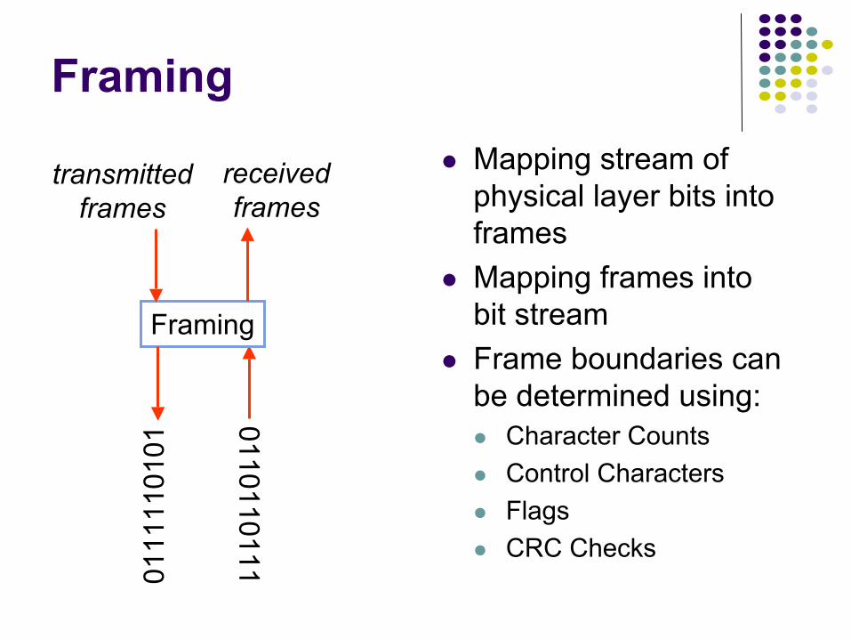
FramingMapping stream of physical layer bits into framesMapping frames into bit streamFrame boundaries can be determined using:
Character CountsControl CharactersFlagsCRC Checks
0110110111
Framing
receivedframes
0111
1101
01transmitted
frames
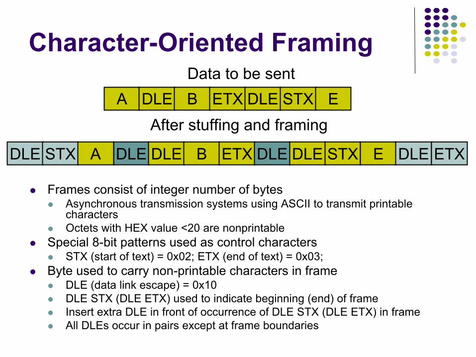
Data to be sentA DLE B ETX DLE STX E
After stuffing and framing
DLE DLE B ETX DLE DLE STXDLE STX A E DLE ETX
Character-Oriented Framing
Frames consist of integer number of bytesAsynchronous transmission systems using ASCII to transmit printable charactersOctets with HEX value <20 are nonprintable
Special 8-bit patterns used as control charactersSTX (start of text) = 0x02; ETX (end of text) = 0x03;
Byte used to carry non-printable characters in frameDLE (data link escape) = 0x10DLE STX (DLE ETX) used to indicate beginning (end) of frame Insert extra DLE in front of occurrence of DLE STX (DLE ETX) in frameAll DLEs occur in pairs except at frame boundaries
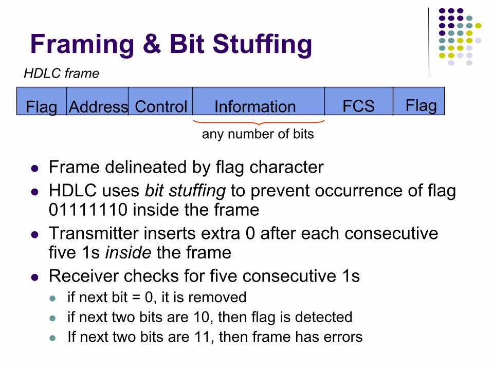
Framing & Bit Stuffing
Frame delineated by flag characterHDLC uses bit stuffing to prevent occurrence of flag 01111110 inside the frame Transmitter inserts extra 0 after each consecutive five 1s inside the frameReceiver checks for five consecutive 1s
if next bit = 0, it is removedif next two bits are 10, then flag is detectedIf next two bits are 11, then frame has errors
Flag FlagAddress Control Information FCS
HDLC frame
any number of bits
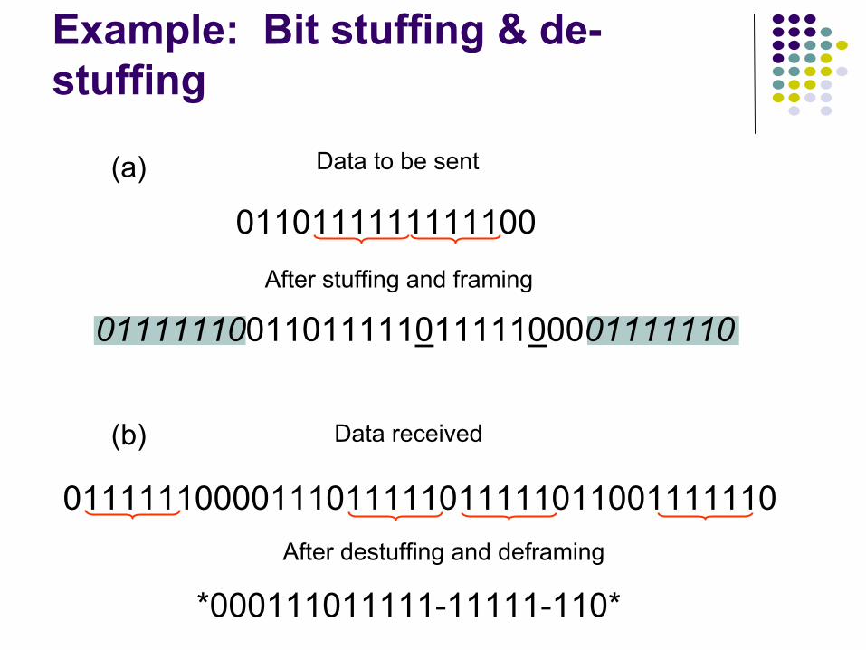
0110111111111100
Data to be sent
After stuffing and framing
0111111001101111101111100001111110
(a)
*000111011111-11111-110*
Data received
After destuffing and deframing
01111110000111011111011111011001111110
(b)
Example: Bit stuffing & de-stuffing
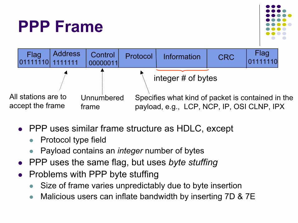
PPP Frame
PPP uses similar frame structure as HDLC, exceptProtocol type fieldPayload contains an integer number of bytes
PPP uses the same flag, but uses byte stuffingProblems with PPP byte stuffing
Size of frame varies unpredictably due to byte insertionMalicious users can inflate bandwidth by inserting 7D & 7E
Flag FlagAddress Control Information CRCProtocol01111110 011111101111111 00000011
Unnumbered frame
Specifies what kind of packet is contained in the payload, e.g., LCP, NCP, IP, OSI CLNP, IPX
All stations are toaccept the frame
integer # of bytes

PPP is character-oriented version of HDLCFlag is 0x7E (01111110)Control escape 0x7D (01111101)Any occurrence of flag or control escape inside of frame is replaced with 0x7D followed by
original octet XORed with 0x20 (00100000)
Byte-Stuffing in PPP
Data to be sent
41 7D 42 7E 50 70 46
After stuffing and framing
5D 42 7D 5E 50 70 467E 41 7D 7E
Chapter 5Peer-to-Peer Protocols
and Data Link Layer
High-Level Data Link Control
High-Level Data Link Control (HDLC)
Bit-oriented data link control Derived from IBM Synchronous Data Link Control (SDLC)Related to Link Access Procedure Balanced (LAPB)
LAPD in ISDNLAPM in cellular telephone signaling
Physicallayer
Data linklayer
Data linklayer
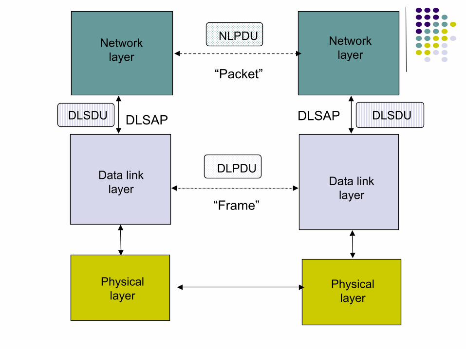
Networklayer
DLSDU DLSDU
Networklayer
Physicallayer
DLPDU
NLPDU
“Packet”
“Frame”
DLSAP DLSAP
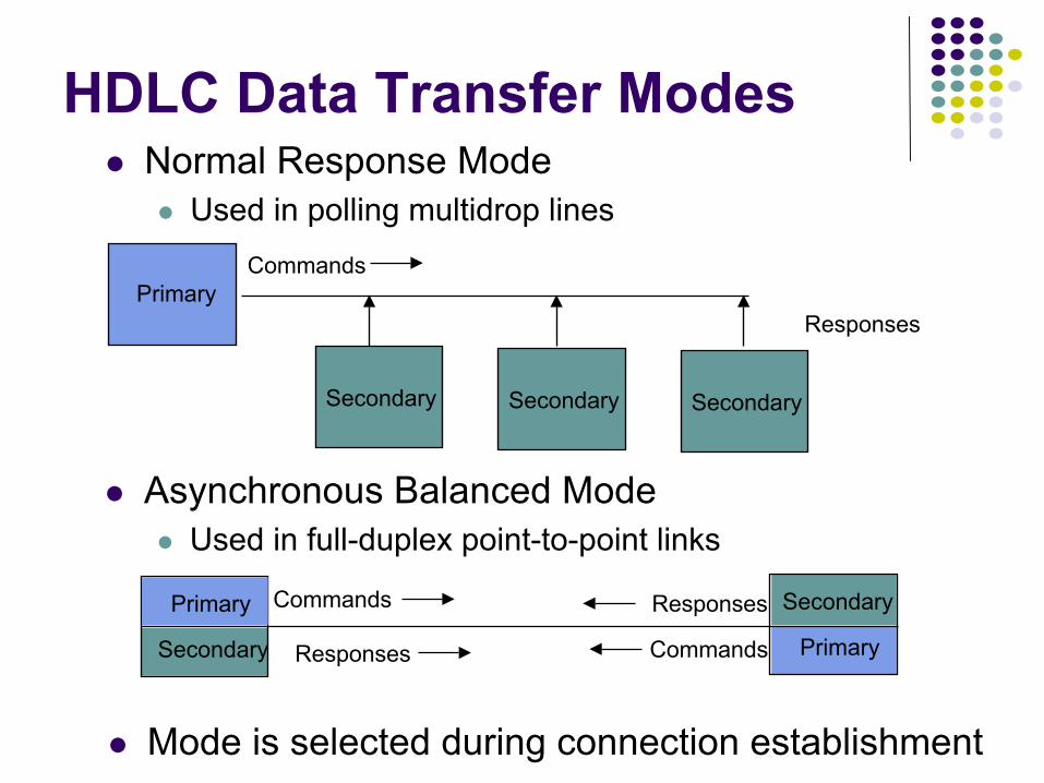
Normal Response ModeUsed in polling multidrop lines
Asynchronous Balanced ModeUsed in full-duplex point-to-point links
HDLC Data Transfer Modes
PrimaryCommands
Responses
Secondary Secondary Secondary
Primary
Secondary
Commands Responses
Primary
Secondary
CommandsResponses
Mode is selected during connection establishment
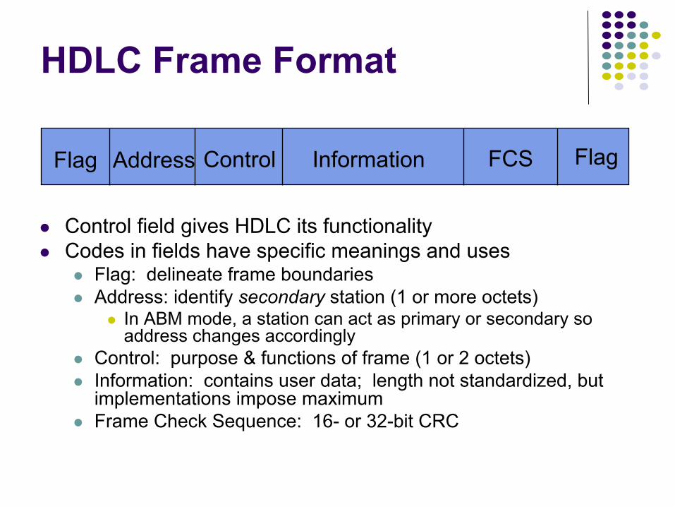
HDLC Frame Format
Control field gives HDLC its functionalityCodes in fields have specific meanings and uses
Flag: delineate frame boundariesAddress: identify secondary station (1 or more octets)
In ABM mode, a station can act as primary or secondary so address changes accordingly
Control: purpose & functions of frame (1 or 2 octets)Information: contains user data; length not standardized, but implementations impose maximumFrame Check Sequence: 16- or 32-bit CRC
Flag FlagAddress Control Information FCS
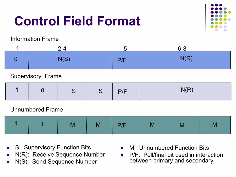
Control Field Format
0 N(S) N(R)P/F
1 2-4 5 6-8Information Frame
N(R)P/F
Supervisory Frame
1 0 S S
Unnumbered Frame
P/F1 1 M M M M M
S: Supervisory Function BitsN(R): Receive Sequence NumberN(S): Send Sequence Number
M: Unnumbered Function Bits P/F: Poll/final bit used in interaction between primary and secondary
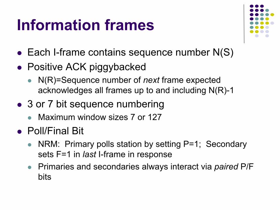
Information framesEach I-frame contains sequence number N(S)Positive ACK piggybacked
N(R)=Sequence number of next frame expected acknowledges all frames up to and including N(R)-1
3 or 7 bit sequence numbering Maximum window sizes 7 or 127
Poll/Final BitNRM: Primary polls station by setting P=1; Secondary sets F=1 in last I-frame in responsePrimaries and secondaries always interact via paired P/F bits
Frames lost due to loss-of-synch or receiver buffer overflowFrames may undergo errors in transmissionCRCs detect errors and such frames are treated as lostRecovery through ACKs, timeouts & retransmissionSequence numbering to identify out-of-sequence & duplicate framesHDLC provides for options that implement several ARQ methods
Error Detection & Loss Recovery
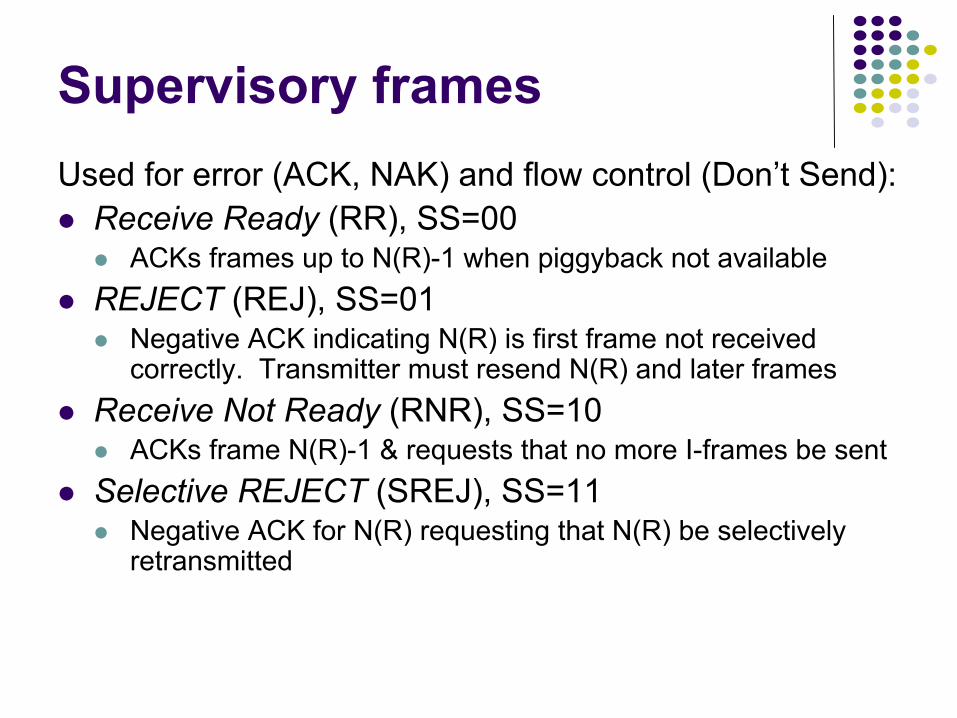
Supervisory framesUsed for error (ACK, NAK) and flow control (Don’t Send):
Receive Ready (RR), SS=00ACKs frames up to N(R)-1 when piggyback not available
REJECT (REJ), SS=01 Negative ACK indicating N(R) is first frame not received correctly. Transmitter must resend N(R) and later frames
Receive Not Ready (RNR), SS=10ACKs frame N(R)-1 & requests that no more I-frames be sent
Selective REJECT (SREJ), SS=11Negative ACK for N(R) requesting that N(R) be selectively retransmitted
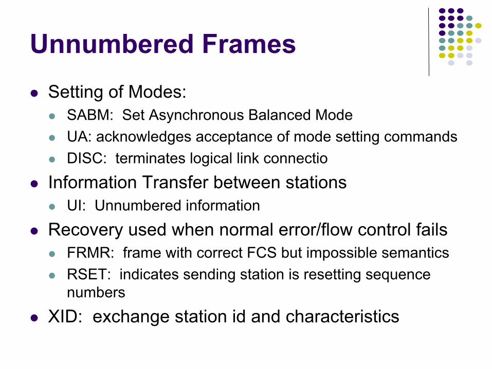
Unnumbered FramesSetting of Modes:
SABM: Set Asynchronous Balanced ModeUA: acknowledges acceptance of mode setting commandsDISC: terminates logical link connectio
Information Transfer between stationsUI: Unnumbered information
Recovery used when normal error/flow control failsFRMR: frame with correct FCS but impossible semanticsRSET: indicates sending station is resetting sequence numbers
XID: exchange station id and characteristics
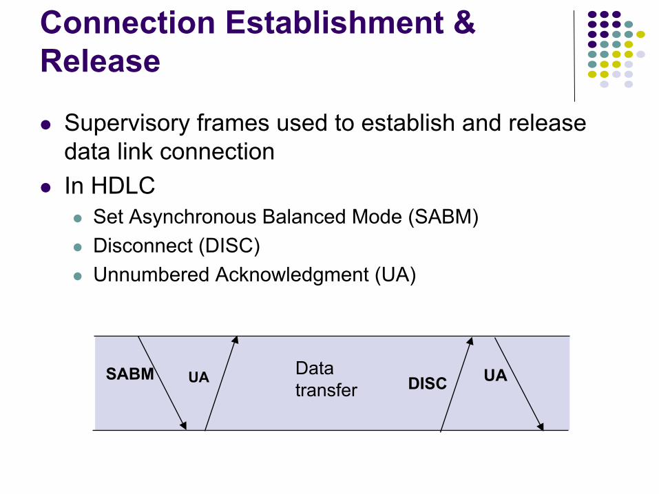
Connection Establishment & Release
Supervisory frames used to establish and release data link connectionIn HDLC
Set Asynchronous Balanced Mode (SABM)Disconnect (DISC)Unnumbered Acknowledgment (UA)
SABM UAUA DISCDatatransfer
Primary A Secondaries B, CB, RR, 0, P
B, I, 0, 0B, I, 1, 0B, I, 2, 0,F
X
B, SREJ, 1C, RR, 0, P
C, RR, 0, F
B, SREJ, 1,P
B, I, 1, 0B, I, 3, 0B, I, 4, 0, F
B, I, 0, 5
Time
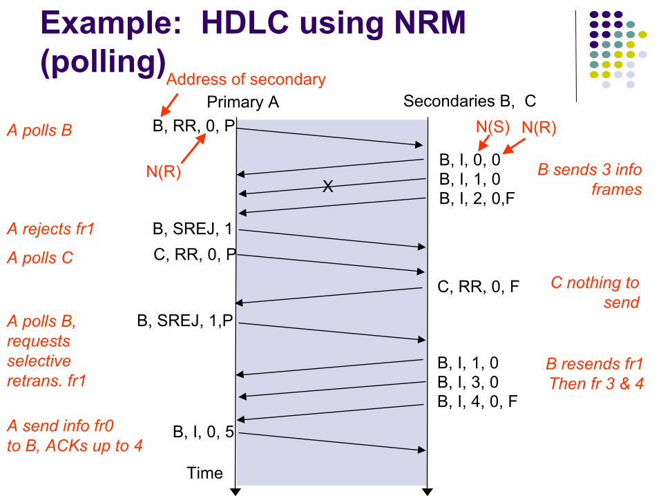
Example: HDLC using NRM (polling)
A polls B
B sends 3 infoframes
A rejects fr1
A polls CC nothing to
sendA polls B, requestsselective retrans. fr1
B resends fr1Then fr 3 & 4
A send info fr0to B, ACKs up to 4
N(R)
N(S) N(R)
Address of secondary
Combined Station A Combined Station BB, I, 0, 0 A, I, 0, 0
B, I, 1, 0
B, I, 2, 1
A, I, 1, 1
A, I, 2, 1
X
B, REJ, 1B, I, 3, 2
B, I, 4, 3
B, I, 1, 3
B, I, 2, 4
B, I, 3, 4
A, I, 3, 1
B, RR, 2
B, RR, 3
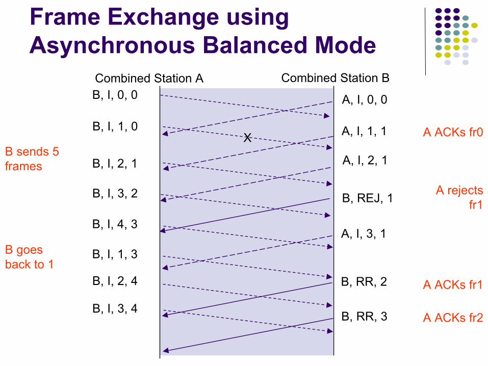
Frame Exchange using Asynchronous Balanced Mode
B sends 5 frames
A ACKs fr0
A rejects fr1
B goes back to 1
A ACKs fr1
A ACKs fr2
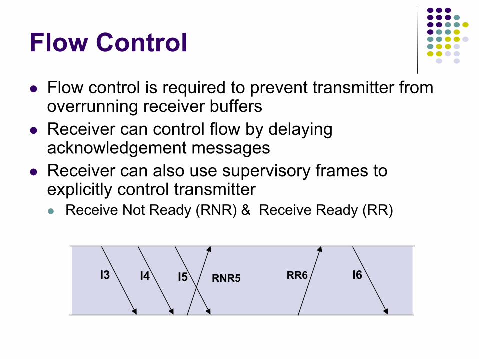
I3 I4 I5 I6RNR5 RR6
Flow ControlFlow control is required to prevent transmitter from overrunning receiver buffersReceiver can control flow by delaying acknowledgement messagesReceiver can also use supervisory frames to explicitly control transmitter
Receive Not Ready (RNR) & Receive Ready (RR)
Chapter 5Peer-to-Peer Protocols
and Data Link Layer
Link Sharing Using Statistical Multiplexing
Buffer
A
B
C
Input lines
Output line
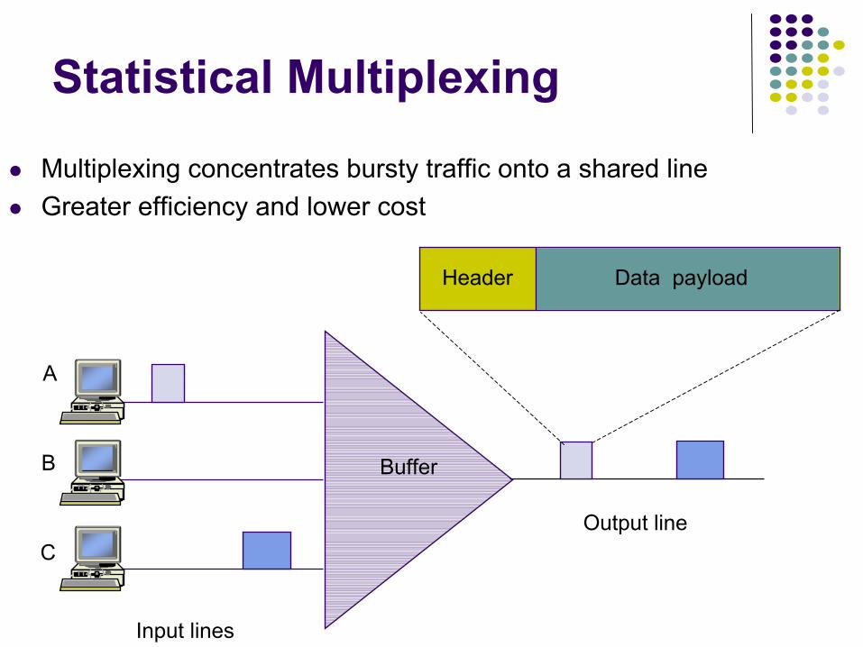
Header Data payload
Statistical Multiplexing
Multiplexing concentrates bursty traffic onto a shared lineGreater efficiency and lower cost
A1 A2
B1 B2
C2C1
A2B1 B2 C2C1
(a)
(b) A1Shared lines
Dedicated lines
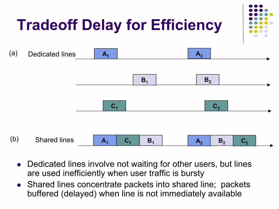
Tradeoff Delay for Efficiency
Dedicated lines involve not waiting for other users, but lines are used inefficiently when user traffic is burstyShared lines concentrate packets into shared line; packets buffered (delayed) when line is not immediately available
1
2
N
1
2
N
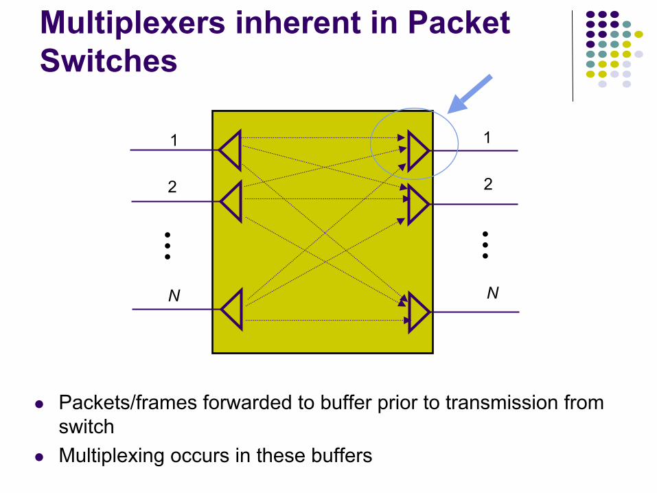
Multiplexers inherent in Packet Switches
Packets/frames forwarded to buffer prior to transmission from switchMultiplexing occurs in these buffers
Buffer
Output line
Input lines
A
B
C
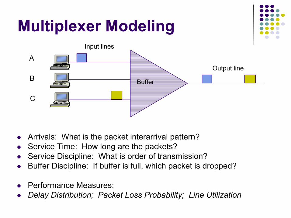
Multiplexer Modeling
Arrivals: What is the packet interarrival pattern?Service Time: How long are the packets?Service Discipline: What is order of transmission?Buffer Discipline: If buffer is full, which packet is dropped?
Performance Measures:Delay Distribution; Packet Loss Probability; Line Utilization
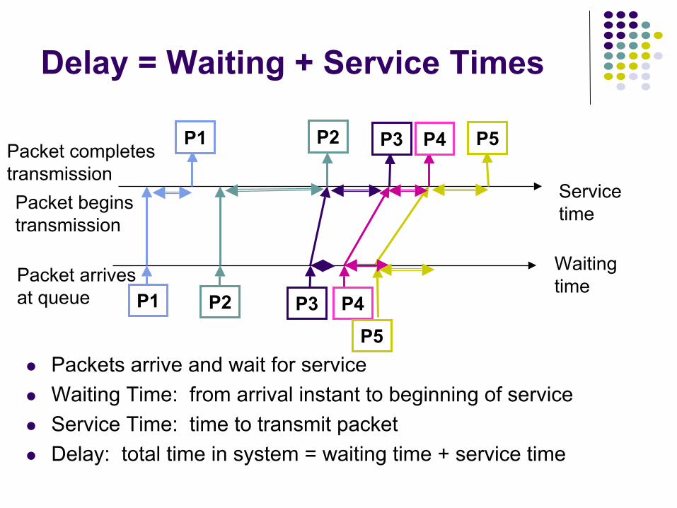
Delay = Waiting + Service Times
Packets arrive and wait for service Waiting Time: from arrival instant to beginning of serviceService Time: time to transmit packetDelay: total time in system = waiting time + service time
Packet arrivesat queue
Packet beginstransmission
Packet completestransmission
Servicetime
Waitingtime
P1
P1
P2
P2
P3
P3
P4
P4
P5
P5
A1 A2
B1 B2
C2C1
A2B1 B2 C2C1
(a)
(b) A1Shared line
Dedicated lines
(c) N(t)
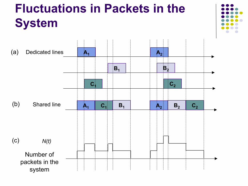
Fluctuations in Packets in the System
Number of packets in the
system


