Chapter 5SLM Production Systems: RecentDevelopments in Process Development,Machine Concepts and Component Design
Reinhart Poprawe, Christian Hinke, Wilhelm Meiners,Johannes Schrage, Sebastian Bremen and Simon Merkt
Abstract The emerging Additive Manufacturing (AM) and especially the Selec-tive Laser Melting (SLM) technologies provide great potential for solving thedilemma between scale and scope, i.e. manufacturing products at mass productioncosts with a maximum fit to customer needs or functional requirements. Due totechnology intrinsic advantages like one-piece-flow capability and almost infinitefreedom of design, Additive Manufacturing was recently even described as “themanufacturing technology that will change the world”. Due to the complex natureof production systems, the technological potential of AM and especially SLM canonly be realised by a holistic comprehension of the complete value creation chain,especially the interdependency between products and production processes.Therefore this paper aims to give an overview regarding recent research in machineconcepts and process development as well as component design which has beencarried out within the cluster of excellence “Integrative production technology forhigh wage countries”.
5.1 Introduction
The overall objective of “ICD-A Individualised Production” within the Cluster ofExcellence is the resolution of the dichotomy between scale and scope, i.e. man-ufacturing products at mass production costs with a maximum fit to customer needsor functional requirements (Schleifenbaum 2011).
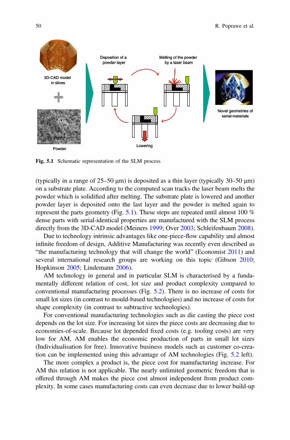
The emerging Additive Manufacturing (AM) and especially the Selective LaserMelting (SLM) technologies provide great potential for solving this dilemma. Withthis layer-based technology the most complex products can be manufacturedwithout tools or moulds. The 3D-CAD model gets sliced layer wise for computingthe scan tracks of the laser beam. In a first manufacturing step powder material
R. Poprawe � C. Hinke (&) � W. Meiners � J. Schrage � S. Bremen � S. MerktFraunhofer Institute for Laser Technology ILT, Steinbachstr. 15, 52074 Aachen, Germanye-mail: [email protected]
(typically in a range of 25–50 μm) is deposited as a thin layer (typically 30–50 μm)on a substrate plate. According to the computed scan tracks the laser beam melts thepowder which is solidified after melting. The substrate plate is lowered and anotherpowder layer is deposited onto the last layer and the powder is melted again torepresent the parts geometry (Fig. 5.1). These steps are repeated until almost 100 %dense parts with serial-identical properties are manufactured with the SLM processdirectly from the 3D-CAD model (Meiners 1999; Over 2003; Schleifenbaum 2008).
Due to technology intrinsic advantages like one-piece-flow capability and almostinfinite freedom of design, Additive Manufacturing was recently even described as“the manufacturing technology that will change the world” (Economist 2011) andseveral international research groups are working on this topic (Gibson 2010;Hopkinson 2005; Lindemann 2006).
AM technology in general and in particular SLM is characterised by a funda-mentally different relation of cost, lot size and product complexity compared toconventional manufacturing processes (Fig. 5.2). There is no increase of costs forsmall lot sizes (in contrast to mould-based technologies) and no increase of costs forshape complexity (in contrast to subtractive technologies).
For conventional manufacturing technologies such as die casting the piece costdepends on the lot size. For increasing lot sizes the piece costs are decreasing due toeconomies-of-scale. Because lot depended fixed costs (e.g. tooling costs) are verylow for AM, AM enables the economic production of parts in small lot sizes(Individualisation for free). Innovative business models such as customer co-crea-tion can be implemented using this advantage of AM technologies (Fig. 5.2 left).
The more complex a product is, the piece cost for manufacturing increase. ForAM this relation is not applicable. The nearly unlimited geometric freedom that isoffered through AM makes the piece cost almost independent from product com-plexity. In some cases manufacturing costs can even decrease due to lower build-up
Novel geometries ofserial-materials
3D-CAD model in slices
Powder
Deposition of apowder layer
Melting of the powderby a laser beam
Lowering
Novel geometries ofserial-materials
3D-CAD model in slices
Powder
Deposition of apowder layer
Melting of the powderby a laser beam
Lowering
Fig. 5.1 Schematic representation of the SLM process
50 R. Poprawe et al.
volumes of optimized products with high geometric complexity. Topology opti-misation is one design approach to save weight while functionally adapting theproduct design to predefined load cases (Huang 2007). These different relationsbetween piece cost and product complexity offer a unique capability for AM tomanufacture innovative products perfectly adapted to the specific technologicalrequirements through the integration of lattice structures (Fig. 5.2 right).
Due to the complex nature of production systems, the technological potential ofAM and especially SLM can only be realised by a holistic comprehension of thecomplete value creation chain, especially the interdependency between productsand production processes.
Therefore this paper aims to give an overview regarding recent research inmachine concepts and process development as well as component design which hasbeen carried out within the cluster of excellence “Integrative production technologyfor high wage countries”.
5.2 SLM Machine Concepts
State-of-the-art SLM machines are typically equipped with a 400 W laser beamsource and a build space of 250 × 250 × 300 mm3. There are different ways toincrease the productivity of SLM machines in terms of process build rate. In generalthe productivity can be increase by the following measures:
Increase of laser power to increase the scanning speed, use bigger layer thicknessand bigger beam diameter to increase the build-up speed.
Product complexity
Additive Manufacturing
High Speed Additive Manufacturing
Conventional Manufacturing
Lot size
Additive Manufacturing
High Speed Additive Manufacturing
ConventionalManufacturing
Individualisation for free Complexity for free
Cost Cost
Innovative business models Innovative products
Fig. 5.2 Innovative business models and innovative products enabled by Additive Manufacturing
5 SLM Production Systems: Recent Developments … 51
By increasing the build volume more parts can be manufactured in one build job.Hence, the number of necessary machine set-up and part removal procedures can bereduced.
Another method to increase the productivity is the parallelisation of the SLMprocess by using multiple laser beam sources and multi laser-scanning-systems inone machine. Either the build area can be multiplied or one build space can beprocessed by multi lasers and scanning-systems at the time.
The SLM machine X-line 1000R by Concept Lasers that was presented at theEuromold (2012) comprises a big build space of 630 × 400 × 500 mm3 that can beprocessed with one laser-scanning-system that is moved above the build platform(Fig. 5.3). This machine is equipped with two process chambers that are rotatable.One process chamber can be prepared for the next build job while in the second onethe SLM process can take place (Concept Laser 2014).
Another example of a SLM machine with an increased build volume is the SLMmachine SLM500HL by SLM Solutions. The build volume is 500 × 280 × 335 mm3.The process chamber can be moved inside and out of the machine. The preparationof the build space can be done outside of the process chamber. The SLM machineSLM500HL can be equipped with up to 4 laser beam sources with that the build arecan be processed at the same time. Furthermore the so called skin-core build strategycan be performed. The beam with a small diameter (dS = 80 µm) and up to a laserpower of 400 W is used to build up the outer shape of the parts (skin). A laser beamwith big beam diameter (dS = 700 µm) and laser power up to 1 kW is used to buildthe inner core of the part (core). So the build up speed can be elevated whilemaintaining the part accuracy (SLM Solutions 2014).
Fig. 5.3 SLM machine concepts for increasing the productivity
52 R. Poprawe et al.
5.2.1 Valuation Method for SLM Machine Concepts
For the comparison and the evaluation of different SLM machine concepts not onlythe investment costs of the machine have to be taken into account but also the coststhat are caused during the whole utilization time. Therefore a suitable valuationmethod has to be found.
One approach is to analyse the life cycle costs (such as the machine price,maintenance costs and energy costs) and the cost of the life cycle performance(such as “laser-on-time” to “laser-off time”).
In typical cost models for SLM investment evaluation the machine hourly rate isused to calculate the price for the SLM manufactured part. Furthermore, cost andtime factors for preparation and follow steps may be included in the calculation(Rickenbacher 2013).
In a life cycle cost analysis, including the identification of cost drivers is carriedout for additively manufactured components (Lindemann 2012). As the main costdriver, the machine costs (73 %) and material costs (11 %) were followed by thecost of any demand (7 %) and preparatory work (4 %) are identified.
In none of those cost models the influence of the SLM machine concept (buildspace, laser power, etc.) is analysed in detail. The cost drivers of those SLMmachines are undiscovered.
A life cycle cost based model is developed to create a possibility to comparedifferent SLM machine concepts.
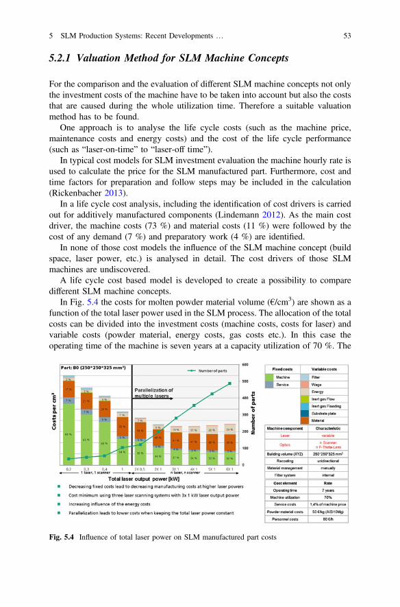
In Fig. 5.4 the costs for molten powder material volume (€/cm3) are shown as afunction of the total laser power used in the SLM process. The allocation of the totalcosts can be divided into the investment costs (machine costs, costs for laser) andvariable costs (powder material, energy costs, gas costs etc.). In this case theoperating time of the machine is seven years at a capacity utilization of 70 %. The
Fig. 5.4 Influence of total laser power on SLM manufactured part costs
5 SLM Production Systems: Recent Developments … 53
build space is considered with 250 × 250 × 325 mm3 and the part to be manu-factured is a space-filling solid cuboid of the dimension of 250 × 250 × 325 mm3.Here only one laser-scanning system is used up to 1 kW total laser power. At totallaser power >1 kW the SLM process is parallelised by integrating multiple laserscanner systems in one SLM machine.
The findings are: The costs of molten material are reduced when using highertotal laser power due to increasing productivity. The minimum costs are found at atotal laser power of 3 kW, which is provided by 3 × 1 kW laser and scannersystems. With further increase of the total laser power (>3 kW) and hence inte-grating more laser beam sources and more laser-scanning systems the increasingenergy costs lead to an increase in total manufacturing costs.
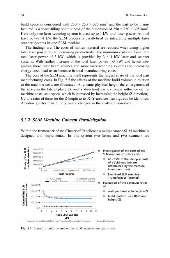
The cost of the SLM machine itself represents the largest share of the total partmanufacturing costs. In Fig. 5.5 the effects of the machine build volume in relationto the machine costs are illustrated. At a same physical height the enlargement ofthe space in the lateral plane (X and Y direction) has a stronger influence on themachine costs, as a space, which is increased by increasing the height (Z direction).Up to a ratio of three for the Z-height to its X–Y-area cost savings can be identified.At ratios greater than 3, only minor changes in the costs are observed.
5.2.2 SLM Machine Concept Parallelization
Within the framework of the Cluster of Excellence a multi-scanner-SLM machine isdesigned and implemented. In this system two lasers and two scanners are
Fig. 5.5 Impact of build volume on the SLM manufactured part costs
54 R. Poprawe et al.
integrated. These two scanners can be positioned to each other that both either scantwo fields on its own (double-sized build space) or one scan field is processed withtwo scanners simultaneously (Fig. 5.6).
With these multi-scanner systems new scanning strategies can be developed andimplemented (Fig. 5.7).
Scanning strategy 1: Both scan fields are positioned next to each other with aslight overlap. This results in a doubling of the build area. By using two laser beam
Fig. 5.6 SLM machine concept of parallelization
Fig. 5.7 New SLM laser processing strategies with two lasers and two scanning systems
5 SLM Production Systems: Recent Developments … 55
sources and two laser-scanning systems both scan fields can be processed at thesame time. In this case the build-up rate is doubled.
Scanning strategy 2: The two laser beam sources and the two laser-scanning sys-tems expose the same build area. Again, a doubling of the build-up rate is achieved. Inaddition, new process strategies may be developed: A laser beam is used for pre-heating the powder material that is followed by a second laser beam that melts thepowder afterwards.
5.3 Process Development
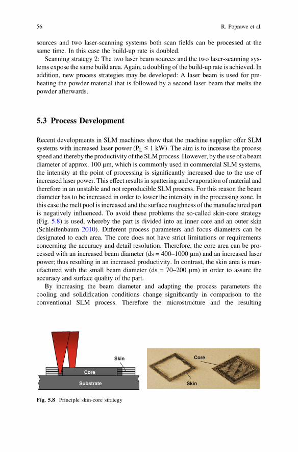
Recent developments in SLM machines show that the machine supplier offer SLMsystems with increased laser power (PL ≤ 1 kW). The aim is to increase the processspeed and thereby the productivity of the SLMprocess. However, by the use of a beamdiameter of approx. 100 µm, which is commonly used in commercial SLM systems,the intensity at the point of processing is significantly increased due to the use ofincreased laser power. This effect results in spattering and evaporation of material andtherefore in an unstable and not reproducible SLM process. For this reason the beamdiameter has to be increased in order to lower the intensity in the processing zone. Inthis case the melt pool is increased and the surface roughness of the manufactured partis negatively influenced. To avoid these problems the so-called skin-core strategy(Fig. 5.8) is used, whereby the part is divided into an inner core and an outer skin(Schleifenbaum 2010). Different process parameters and focus diameters can bedesignated to each area. The core does not have strict limitations or requirementsconcerning the accuracy and detail resolution. Therefore, the core area can be pro-cessed with an increased beam diameter (ds = 400–1000 μm) and an increased laserpower; thus resulting in an increased productivity. In contrast, the skin area is man-ufactured with the small beam diameter (ds = 70–200 μm) in order to assure theaccuracy and surface quality of the part.
By increasing the beam diameter and adapting the process parameters thecooling and solidification conditions change significantly in comparison to theconventional SLM process. Therefore the microstructure and the resulting
Substrate
Core
Skin
Skin
Core
Fig. 5.8 Principle skin-core strategy
56 R. Poprawe et al.
mechanical properties have to be investigated in detail. These investigations aredone for the maraging tool steel 1.2709 within the Cluster of excellence.
The first step is to investigate process parameters on cubic test samples whichhave a averaged density of ≥99.5 %. Therefore a SLM machine setup with a laserbeam diameter of ds = 80 µm (Gaussian beam profile) and ds = 728 µm (Top-hatbeam profile) is used. The results for the achieved theoretical build-up rate which iscalculated by the product of hatch distance, layer thickness and scanning velocity isillustrated in Fig. 5.9. It can be observed that by the increase of the laser power from300 W up to PL = 1 kW and an adaption of the process parameters layer thicknessand scanning velocity the theoretical build up rate can be increased from 3 mm3/s to15 mm3/s. A further increase of the laser power up to PL = 2 kW results in anincrease of the theoretical build-up rate to 26 mm3/s (factor 8,9). These investi-gations show that it is possible with the use of increased laser power up toPL = 2 KW to heighten the theoretical build-up rate and thereby the productivitysignificantly.
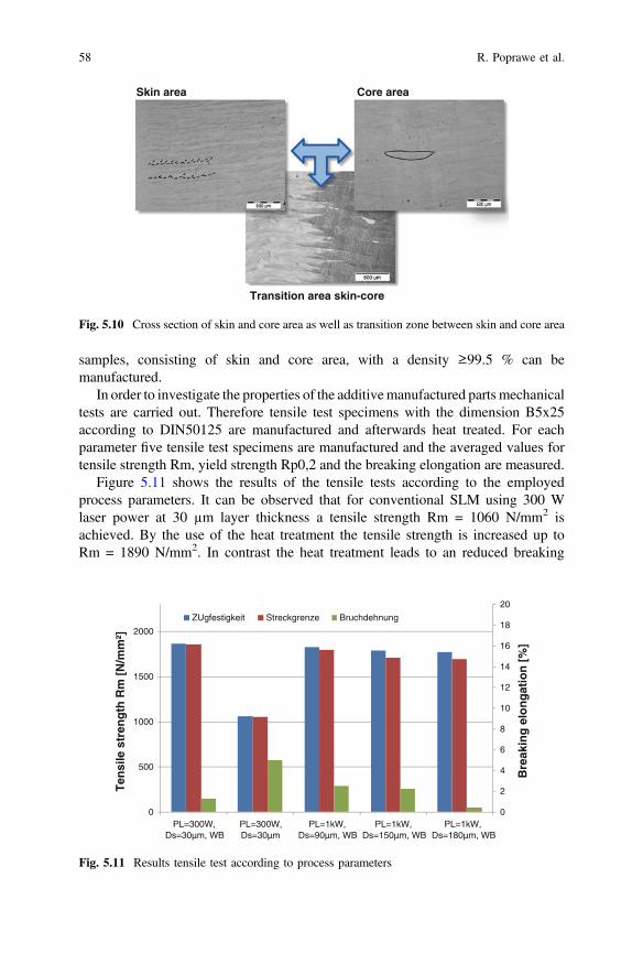
After the investigation of process parameters the microstructure for the manu-factured test samples is investigated. Especially the transition zone between skinand core area has to be investigated in order to assure a metallurgical bondingbetween skin and core area. Due to the different layer thicknesses (Ds,skin = 30 µm,Ds,core = 60–150 µm) the scanning strategy has to be adapted.
Figure 5.10 shows etched cross section of the skin and core area as well as thetransition zone between skin and core area. It can be observed that due to the use ofthe increased beam diameter the melt pool size is significantly increased. In additionthe transition zone between skin and core area shows no defects and metallurgicalbonding. As a result it can be noted that by the use of the skin-core strategy, test
0,0
5,0
10,0
15,0
20,0
25,0
30,0
0,06 0,09 0,12 0,15
Th
eore
tica
l bu
ild-u
pra
te V
th[m
m³/
s]
Layer thickness Ds [mm]
PL=1kW PL=1,5kW PL=2kW
Reference Conv. SLM (PL=300W | ds =70µm)
x 8,9
Fig. 5.9 Theoretical build up rate according to layer thickness and laser power processing the toolsteel 1.2709
5 SLM Production Systems: Recent Developments … 57
samples, consisting of skin and core area, with a density ≥99.5 % can bemanufactured.
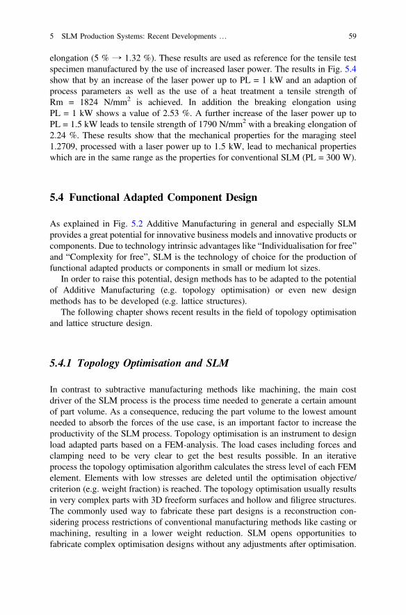
In order to investigate the properties of the additivemanufactured parts mechanicaltests are carried out. Therefore tensile test specimens with the dimension B5x25according to DIN50125 are manufactured and afterwards heat treated. For eachparameter five tensile test specimens are manufactured and the averaged values fortensile strength Rm, yield strength Rp0,2 and the breaking elongation are measured.
Figure 5.11 shows the results of the tensile tests according to the employedprocess parameters. It can be observed that for conventional SLM using 300 Wlaser power at 30 µm layer thickness a tensile strength Rm = 1060 N/mm2 isachieved. By the use of the heat treatment the tensile strength is increased up toRm = 1890 N/mm2. In contrast the heat treatment leads to an reduced breaking
0
2
4
6
8
10
12
14
16
18
20
0
500
1000
1500
2000
PL=300W,Ds=30µm, WB
PL=300W,Ds=30µm
PL=1kW,Ds=90µm, WB
PL=1kW,Ds=150µm, WB
PL=1kW,Ds=180µm, WB
Bre
akin
g e
lon
gat
ion
[%
]
Ten
sile
str
eng
th R
m [
N/m
m²]
ZUgfestigkeit Streckgrenze Bruchdehnung
Fig. 5.11 Results tensile test according to process parameters
Skin area Core area
Transition area skin-core
Fig. 5.10 Cross section of skin and core area as well as transition zone between skin and core area
58 R. Poprawe et al.
elongation (5 % → 1.32 %). These results are used as reference for the tensile testspecimen manufactured by the use of increased laser power. The results in Fig. 5.4show that by an increase of the laser power up to PL = 1 kW and an adaption ofprocess parameters as well as the use of a heat treatment a tensile strength ofRm = 1824 N/mm2 is achieved. In addition the breaking elongation usingPL = 1 kW shows a value of 2.53 %. A further increase of the laser power up toPL = 1.5 kW leads to tensile strength of 1790 N/mm2 with a breaking elongation of2.24 %. These results show that the mechanical properties for the maraging steel1.2709, processed with a laser power up to 1.5 kW, lead to mechanical propertieswhich are in the same range as the properties for conventional SLM (PL = 300 W).
5.4 Functional Adapted Component Design
As explained in Fig. 5.2 Additive Manufacturing in general and especially SLMprovides a great potential for innovative business models and innovative products orcomponents. Due to technology intrinsic advantages like “Individualisation for free”and “Complexity for free”, SLM is the technology of choice for the production offunctional adapted products or components in small or medium lot sizes.
In order to raise this potential, design methods has to be adapted to the potentialof Additive Manufacturing (e.g. topology optimisation) or even new designmethods has to be developed (e.g. lattice structures).
The following chapter shows recent results in the field of topology optimisationand lattice structure design.
5.4.1 Topology Optimisation and SLM
In contrast to subtractive manufacturing methods like machining, the main costdriver of the SLM process is the process time needed to generate a certain amountof part volume. As a consequence, reducing the part volume to the lowest amountneeded to absorb the forces of the use case, is an important factor to increase theproductivity of the SLM process. Topology optimisation is an instrument to designload adapted parts based on a FEM-analysis. The load cases including forces andclamping need to be very clear to get the best results possible. In an iterativeprocess the topology optimisation algorithm calculates the stress level of each FEMelement. Elements with low stresses are deleted until the optimisation objective/criterion (e.g. weight fraction) is reached. The topology optimisation usually resultsin very complex parts with 3D freeform surfaces and hollow and filigree structures.The commonly used way to fabricate these part designs is a reconstruction con-sidering process restrictions of conventional manufacturing methods like casting ormachining, resulting in a lower weight reduction. SLM opens opportunities tofabricate complex optimisation designs without any adjustments after optimisation.
5 SLM Production Systems: Recent Developments … 59
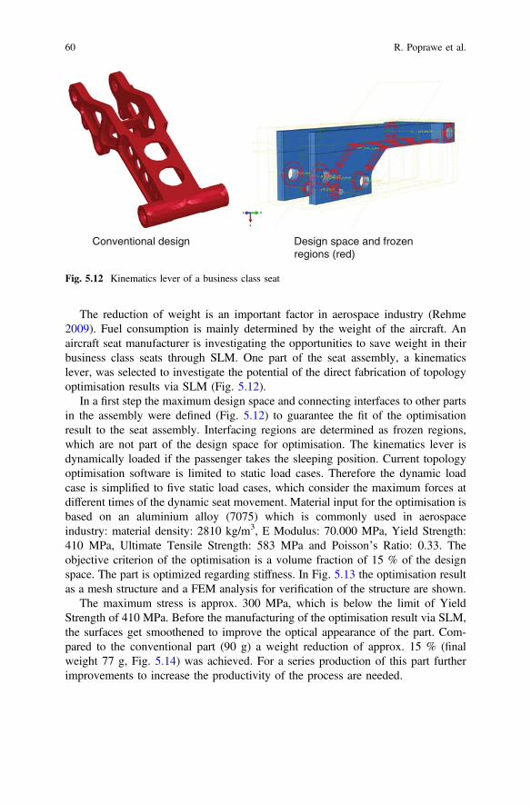
The reduction of weight is an important factor in aerospace industry (Rehme2009). Fuel consumption is mainly determined by the weight of the aircraft. Anaircraft seat manufacturer is investigating the opportunities to save weight in theirbusiness class seats through SLM. One part of the seat assembly, a kinematicslever, was selected to investigate the potential of the direct fabrication of topologyoptimisation results via SLM (Fig. 5.12).
In a first step the maximum design space and connecting interfaces to other partsin the assembly were defined (Fig. 5.12) to guarantee the fit of the optimisationresult to the seat assembly. Interfacing regions are determined as frozen regions,which are not part of the design space for optimisation. The kinematics lever isdynamically loaded if the passenger takes the sleeping position. Current topologyoptimisation software is limited to static load cases. Therefore the dynamic loadcase is simplified to five static load cases, which consider the maximum forces atdifferent times of the dynamic seat movement. Material input for the optimisation isbased on an aluminium alloy (7075) which is commonly used in aerospaceindustry: material density: 2810 kg/m3, E Modulus: 70.000 MPa, Yield Strength:410 MPa, Ultimate Tensile Strength: 583 MPa and Poisson’s Ratio: 0.33. Theobjective criterion of the optimisation is a volume fraction of 15 % of the designspace. The part is optimized regarding stiffness. In Fig. 5.13 the optimisation resultas a mesh structure and a FEM analysis for verification of the structure are shown.
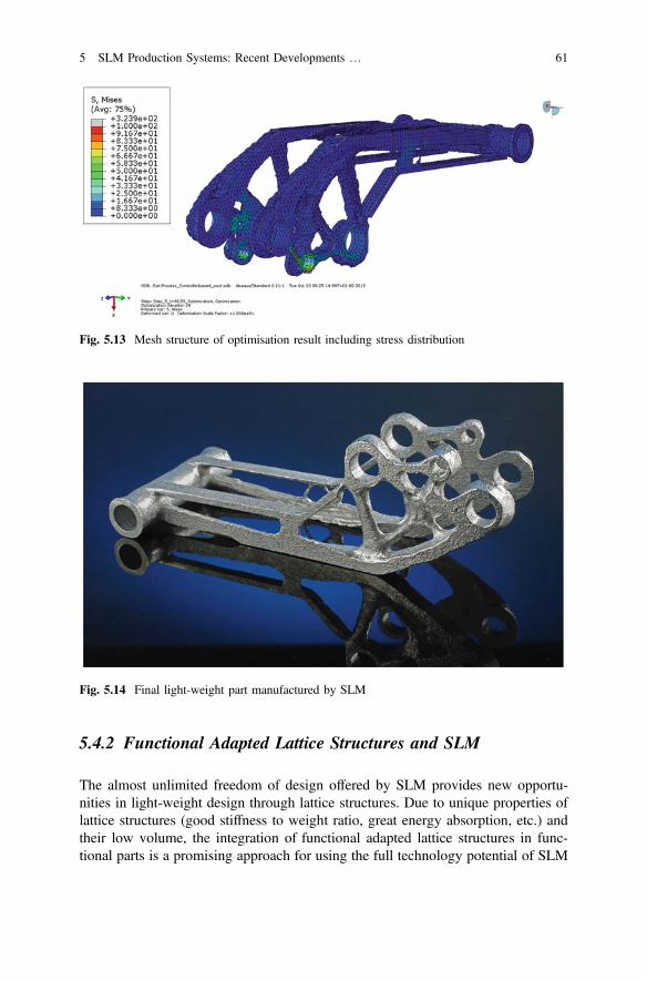
The maximum stress is approx. 300 MPa, which is below the limit of YieldStrength of 410 MPa. Before the manufacturing of the optimisation result via SLM,the surfaces get smoothened to improve the optical appearance of the part. Com-pared to the conventional part (90 g) a weight reduction of approx. 15 % (finalweight 77 g, Fig. 5.14) was achieved. For a series production of this part furtherimprovements to increase the productivity of the process are needed.
Conventional design Design space and frozenregions (red)
Fig. 5.12 Kinematics lever of a business class seat
60 R. Poprawe et al.
5.4.2 Functional Adapted Lattice Structures and SLM
The almost unlimited freedom of design offered by SLM provides new opportu-nities in light-weight design through lattice structures. Due to unique properties oflattice structures (good stiffness to weight ratio, great energy absorption, etc.) andtheir low volume, the integration of functional adapted lattice structures in func-tional parts is a promising approach for using the full technology potential of SLM
Fig. 5.14 Final light-weight part manufactured by SLM
Fig. 5.13 Mesh structure of optimisation result including stress distribution
5 SLM Production Systems: Recent Developments … 61
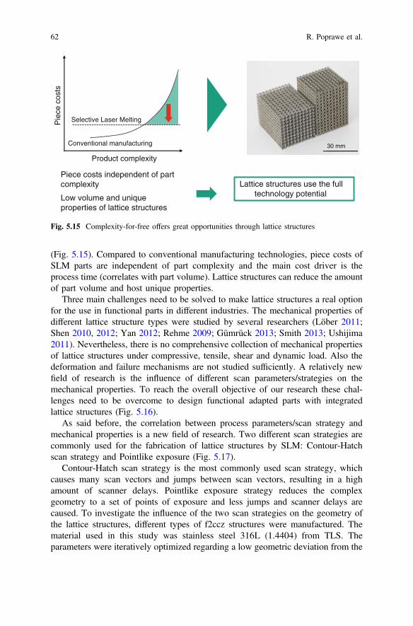
(Fig. 5.15). Compared to conventional manufacturing technologies, piece costs ofSLM parts are independent of part complexity and the main cost driver is theprocess time (correlates with part volume). Lattice structures can reduce the amountof part volume and host unique properties.
Three main challenges need to be solved to make lattice structures a real optionfor the use in functional parts in different industries. The mechanical properties ofdifferent lattice structure types were studied by several researchers (Löber 2011;Shen 2010, 2012; Yan 2012; Rehme 2009; Gümrück 2013; Smith 2013; Ushijima2011). Nevertheless, there is no comprehensive collection of mechanical propertiesof lattice structures under compressive, tensile, shear and dynamic load. Also thedeformation and failure mechanisms are not studied sufficiently. A relatively newfield of research is the influence of different scan parameters/strategies on themechanical properties. To reach the overall objective of our research these chal-lenges need to be overcome to design functional adapted parts with integratedlattice structures (Fig. 5.16).
As said before, the correlation between process parameters/scan strategy andmechanical properties is a new field of research. Two different scan strategies arecommonly used for the fabrication of lattice structures by SLM: Contour-Hatchscan strategy and Pointlike exposure (Fig. 5.17).
Contour-Hatch scan strategy is the most commonly used scan strategy, whichcauses many scan vectors and jumps between scan vectors, resulting in a highamount of scanner delays. Pointlike exposure strategy reduces the complexgeometry to a set of points of exposure and less jumps and scanner delays arecaused. To investigate the influence of the two scan strategies on the geometry ofthe lattice structures, different types of f2ccz structures were manufactured. Thematerial used in this study was stainless steel 316L (1.4404) from TLS. Theparameters were iteratively optimized regarding a low geometric deviation from the
30 mm
Piece costs independent of partcomplexity
Low volume and uniqueproperties of lattice structures
Lattice structures use the fulltechnology potential
Pie
ce c
osts
Selective Laser Melting
Conventional manufacturing
Product complexity
Fig. 5.15 Complexity-for-free offers great opportunities through lattice structures
62 R. Poprawe et al.
CAD model. A measurement of the relative density of the lattice structures byarchimedean density measurement was performed. The relative density is the fillingdegree of the structure and can be used to determine geometric deviations of thestructure. Three different kinds of Contour-Hatch parameters (Laser power:100–130 W, scan speed: 700–900 mm/s) and one parameter set for Pointlikeexposure (Laser power: 182 W) were investigated. Figure 5.18 shows the deviationsof the relative density to the CAD model target for the investigated parameters.
For Pointlike exposure strategy the relative density is 4 % higher than the CADmodel target. All in all, the CAD model target can be reached with low deviations.To further investigate the geometry lattice structures were investigated by micro CTmeasurement. Figure 5.19 shows a reconstruction based on these CT images.
Lattice structures manufactured by Contour-Hatch scan strategy show no visiblebuild-up errors and vertical and diagonal struts have the same diameter. In contrastpointlike exposure strategy show light contractions at knots and deviations betweenvertical and diagonal strut diameter.
Seite 6
Point of exposureHatch scans
Contour scan Melt pool propagation
CAD target
Contour-Hatch Pointlike exposure
Fig. 5.17 Commonly used scan strategies for the fabrication of lattice structures
Challenges:
Mechanical propertiesunknown
Deformation and failuremechanism unknown
Correlation between processparameters / scan strategiesand mechanical properties
Overall objective: Integration of lattice structures in functionalparts
Fig. 5.16 A new way of designing functional parts by the integration of lattice structures
5 SLM Production Systems: Recent Developments … 63
Open Access This chapter is distributed under the terms of the Creative Commons AttributionNoncommercial License, which permits any noncommercial use, distribution, and reproduction inany medium, provided the original author(s) and source are credited.
Acknowledgment The authors would like to thank the German Research Foundation DFG forthe kind support within the Cluster of Excellence “Integrative Production Technology for High-Wage Countries.
PointlikeContour-Hatch
Light contractionsat knots
Deviations between verticaland diagonal struts
No build-up erros
Vertical and diagonal strutshave almost same diameter
Fig. 5.19 Mirco CT reconstructions to investigate the dimensional accuracy of lattice structures
12,0012,2512,5012,7513,0013,2513,5013,7514,00
KH1 KH2 KH3 LP1
+2,7 %
CAD value
+4,0 %
-0,2 %-0,3 %
Relative density (%)
Fig. 5.18 Deviations of relative density to the CAD model target
64 R. Poprawe et al.
References
Concept Laser (2014) Data sheet X line 1000R. http://platforms.monash.edu/mcam/images/stories/Concept/xline_1000.pdf Accessed 02.10.2014
Economist (2011) Cover Story, 12.2.2011Gibson I et al (2010) Additive Manufacturing Technologies. Rapid Prototyping to Direct Digital
Manufacturing, Springer, HeidelbergGümrük R, Mines R A W (2013) Compressive behaviour of stainless steel micro-lattice structures,
International Journal of Mechanical Sciences, 2013Hopkinson N et al (eds) (2005) Rapid Manufacturing: An Industrial Revolution for the Digital
Age. WileyHuang X, Xie M (2010) Evolutionary Topology Optimisation of Continuum Structures: Methods
and Applications. WileyLindemann U (eds) (2006) Individualisierte Produkte - Komplexität beherrschen in Entwicklung
und Produktion, Springer, HeidelbergLindemann C et al (2012) Analyzing Product Lifecycle Costs for a Better Understanding of Cost
Drivers in Additive Manufacturing. In: Proceedings of “International Solid FreeformFabrication Symposium 2012”, Austin Texas
Löber L, Klemm D, Kühn U, Eckert, J (2011) Rapid Manufacturing of Cellular Structures of Steelor Titaniumalumide, MSF (Materials Science Forum), Vol. 690, 2011
Over C (2003) Generative Fertigung von Bauteilen aus Werkzeugstahl X38CrMoV5-1 und TitanTiAL6V4 mit „Selective Laser Melting“. Dissertation, RWTH Aachen
Rehme O (2009) Cellular Design for Laser Freeform Fabrication, PhD Thesis, Laser ZentrumNord, Hamburg
Rickenbacher L (2013) An integrated cost-model for selective laser melting. Rapid PrototypingJournal, Vol. 19 Number 3 2013, pp. 208–214
Schleifenbaum H, Meiners W, Wissenbach K (2008) Towards Rapid Manufacturing for seriesproduction: an ongoing process report on increasing the build rate of Selective Laser Melting(SLM). International Conference on Rapid Prototyping & Rapid Tooling & Rapid Manufac-turing, Berlin, Germany
Schleifenbaum H et al (2010) Individualized production by means of high power Selective LaserMelting. CIRP Journal of Manufacturing Science and Technology, vol 2 (3), pp. 161–169
Schleifenbaum H et al (2011) Werkzeuglose Produktionstechnologien für individualisierteProdukte. In: Brecher C (eds) Integrative Produktionstechnik für Hochlohnländer, Springer
Shen Y, McKown S, Tsopanos S, Sutcliffe C J, Mines R A W, Cantwell W J (2010) TheMechanical Properties of Sandwich Structures Based on Metal Lattice Architectures, Journal ofSandwich Structures and Materials, Vol. 12, 2010
Shen Y, Cantwell W J, Mines R A W, Ushijima K (2012) The Properties of Lattice StructuresManufactured Using Selective Laser Melting, AMR (Advanced Materials Research), Vol. 445,pp. 386–391, 2012
SLM Solutions (2014) Data sheet SLM500HL. http://www.stage.slm-solutions.com/download.php?f=8277396e9b97045edbb7ef680e3ada56 Accessed 02.10.2014
Smith M, Guan Z, Cantwell W J (2013) Finite element modelling of the compressive response oflattice structures manufactured using the selective laser melting technique, International Journalof Mechanical Sciences, 2013
Ushijima K, Cantwell W J, Mines R A W, Tsopanos S, Smith M (2011) An investigation into thecompressive properties of stainless steel micro-lattice structures, Journal of SandwichStructures and Materials, 2011
Yan C, Hao L, Hussein A, Raymont D (2012) Evaluations of cellular lattice structuresmanufactured using selective laser melting, International Journal of Machine Tools andManufacture, Vol 62, pp. 32–38, 2012
5 SLM Production Systems: Recent Developments … 65