October 2021 5-1 Chapter 5 Structures 5.1 Usage This chapter defines a variety of geometric and hydraulic design requirements and guidelines associated with roadway and multimodal bridges, retaining walls, and sound barrier walls. This chapter replaces the former Bridge Policy. Designs shall conform to the requirements of this chapter in the same manner as previous designs conformed to the former Bridge Policy. 5.1.1 Exceptions to Guidelines In general, apply the criteria presented in this chapter unless project-specific conditions dictate otherwise. On a case-by-case basis, develop project-specific design criteria during NCDOT Project Delivery Network (PDN) activity 2RD1 for projects with special requirements, such as: • Bridges with long spans • Bridges with total lengths greater than 200 feet • Locations with special significance, such as: – Close proximity to historic sites or public parks – Movable bridges or other specialty structure types – Other special features. Consider items such as: • Unique site conditions • Stakeholder agency requirements • Accident experience • Future traffic growth (which may suggest providing wider bridge decks or larger horizontal clearances to accommodate future widening of facilities) • Commitments documented in the National Environmental Policy Act/State Environmental Policy Act (NEPA/SEPA) documents (PDN Activity 2EP1). As an example, an exception may be considered when more cost-effective criteria are warranted to provide continuity along the existing facility. Such exceptions may be warranted when the project involves little or no approach roadway work and additional improvements to the facility are not anticipated in the near future. Such project-specific design criteria may deviate from guidance presented here and elsewhere in the RDM. Coordinate with the Project Manager, NCDOT discipline leads, and NCDOT Division representatives as needed when considering deviations from the criteria. Refer to RDM Part II Chapter 7 for guidance on design exceptions. 5.1.2 Existing Bridges to Remain Over time, facility improvements encourage higher speeds and attract larger vehicles. Existing substandard structures may need rehabilitation, widening, or replacement. Because of the high cost of new structures, existing bridges and culverts that meet acceptable criteria should be retained.
Transcript
October 2021 5-1
Chapter 5 Structures 5.1 Usage This chapter defines a variety of geometric and hydraulic design requirements and guidelines associated with roadway and multimodal bridges, retaining walls, and sound barrier walls. This chapter replaces the former Bridge Policy. Designs shall conform to the requirements of this chapter in the same manner as previous designs conformed to the former Bridge Policy.
5.1.1 Exceptions to Guidelines In general, apply the criteria presented in this chapter unless project-specific conditions dictate otherwise. On a case-by-case basis, develop project-specific design criteria during NCDOT Project Delivery Network (PDN) activity 2RD1 for projects with special requirements, such as:
• Bridges with long spans
• Bridges with total lengths greater than 200 feet
• Locations with special significance, such as:
– Close proximity to historic sites or public parks
– Movable bridges or other specialty structure types
– Other special features. Consider items such as:
• Unique site conditions
• Stakeholder agency requirements
• Accident experience
• Future traffic growth (which may suggest providing wider bridge decks or larger horizontal clearances to accommodate future widening of facilities)
• Commitments documented in the National Environmental Policy Act/State Environmental Policy Act (NEPA/SEPA) documents (PDN Activity 2EP1).
As an example, an exception may be considered when more cost-effective criteria are warranted to provide continuity along the existing facility. Such exceptions may be warranted when the project involves little or no approach roadway work and additional improvements to the facility are not anticipated in the near future. Such project-specific design criteria may deviate from guidance presented here and elsewhere in the RDM. Coordinate with the Project Manager, NCDOT discipline leads, and NCDOT Division representatives as needed when considering deviations from the criteria. Refer to RDM Part II Chapter 7 for guidance on design exceptions.
5.1.2 Existing Bridges to Remain Over time, facility improvements encourage higher speeds and attract larger vehicles. Existing substandard structures may need rehabilitation, widening, or replacement. Because of the high cost of new structures, existing bridges and culverts that meet acceptable criteria should be retained.
Roadway Design Manual Structures
October 2021 5-2
Where an existing highway is to be reconstructed or widened, retain existing bridges that meet the following criteria:
1. The bridge geometry fits the proposed alignment and profile. 2. The bridge is structurally sound. 3. Bridge rails meet, or can be upgraded to meet, current performance requirements. 4. The safe load carrying capacity meets current performance requirements (see below). 5. There is no significant accident history in the vicinity of the existing bridge. 6. The bridge clear deck width meets requirements defined herein.
Existing bridges that meet the above criteria except that they provide deficient clear deck width should be considered for widening. In such cases, widen the bridge to the same dimension as recommended for a new bridge. See Table 5-1 for minimum clear roadway width and vertical clearance requirements for existing bridges to remain in place. The guidance in Table 5-1 reflects traditional policy; this guidance is in the process of being revised in a future update.
Table 5-1 Minimum Clear Roadway Width and Vertical Clearances for Existing Bridges to Remain in Place
Minimum Clear Roadway Width for Existing Bridges to Remain in Place
Local Design ADT 1 Local 2 Design ADT Collector 2 Arterial Freeway Interstate
≤ 250 20′ ≤ 400 22′ 28′ 3,7
251 to 1,500 22′ 401 to 1,500 22′ 28′ 3,7
1,501 to 2000 24′ 1,501 to 2,000
24′ 28′ 3,7
> 2,000 28′ > 2,000 28′ 28′ 24′ plus paved
shoulders 4
24′ plus paved
shoulders 5
Minimum Vertical Clearances for Existing Bridges to Remain in Place
14′ 14′ 14′ 14′ 16′ 6
Notes: 1. ADT = Average Daily Traffic. 2. Bridges longer than 100′ may be analyzed individually in accordance with recommended minimum width of traveled way and
shoulders in the GB, referring to the appropriate chapter based on roadway functional classification. The designer should consider the condition of the structure, the clear width provided, crash history, traffic volumes, design speed, snow storage, and other pertinent factors.
3. For arterials with 11′ lanes and design speeds of 40 mph or less, 26′ may be used. 4. As a minimum, an Accident History Evaluation should be completed to determine if additional width is required. Ultimate
widening should be considered for all existing bridges with less than 3′ offsets to parapets. Bridges longer than 200′ may be analyzed individually.
5. Bridges longer than 200′ may be analyzed individually in accordance with recommended minimum width of traveled way and shoulders in the GB Chapter 8 Section 8.2.4. The designer should consider the condition of the structure, the clear width provided, crash history, traffic volumes, design speed, snow storage, and other pertinent factors (4′ minimum offset to parapet required).
6. Minimum 14′ on Urban Interstate when there is an Alternate Interstate Routing with 16′ clearance. 7. Width of travel way may remain at 22′ (plus paved shoulders) on reconstructed highways where alignment and safety records
are satisfactory.
Roadway Design Manual Structures
October 2021 5-3
The Structures Lead should determine the required safe load carrying capacity of existing bridges during PDN Activity 1ST1, Initiate Structures Investigation. To consider retaining an existing bridge in place, it should provide the following safe load carrying capacity:
• Bridges carrying interstate, freeway, or arterial traffic – The safe load carrying capacity should be 10 percent greater than that required to carry North Carolina Legal Loads when load-rated in accordance with the NCDOT Structures Management Unit Manual.
• Bridges carrying local and collector traffic – The bridge shall be load-rated (and load posted, if necessary) in accordance with the NCDOT Structures Management Unit Manual to a weight limit determined to meet the needs of the route served; however, the safe load capacity shall be sufficient to carry school buses and vital services vehicles where there is no reasonable or adequate alternate route.
5.2 Guidelines for Sub Regional Tier Bridge Projects 5.2.1 Usage The Sub Regional Tier Design Guidelines (SRTG) in this section define the design requirements for bridge replacement projects only on North Carolina Highway System facilities designated as minor collectors, local, or secondary roads. This section replaces the former SRTG (February 2008). Qualifying designs shall conform to the requirements of this section in the same manner as previous designs conformed to the former SRTG (February 2008). Projects at locations identified by North Carolina’s Highway Safety Improvement Program are not eligible for design under the SRTG. The SRTG establish broad limits by presenting minimum values for design to minimize the amount of approach work and to maximize the limited funds available for the bridge program. Consider site-specific conditions and apply prudent engineering judgment when applying these guidelines. Design projects to provide safety and desirable levels of service appropriate to the social, economic, and environmental conditions of each project. The SRTG establish bridge replacement design criteria intended to maintain current operating conditions without compromising safety. These guidelines emphasize minimizing changes in the vertical grade, structure length and width, approach roadway limits, and right of way for each site. When appropriate, consider options to rehabilitate rather than replace existing bridges and options to use accelerated construction techniques. Coordinate with the Project Manager, Structures Lead, Hydraulic Design Engineer, Design Geotechnical Engineer, Traffic Analysis Engineer, NEPA/SEPA Lead, and Division Engineer or Project Management Unit, as appropriate, during PDN Activity 1FS3, Complete Project Scoping Report, to determine whether to design the project following the SRTG.
5.2.2 Geometric Design Criteria During PDN Activity 1RD1, Initiate Roadway Coordination, obtain available traffic forecasts developed by the Traffic Analysis Engineer during PDN Activity 1TP1 and available safety data (e.g., crash data, available volumes including non-motorists, and roadway characteristics data) developed by the Traffic Safety Planning Engineer during PDN Activity 1TS1. If traffic forecasts for the facility are not available, use engineering judgment to interpret other nearby available traffic data. When crash and severity rates are below the statewide averages, use the geometric design criteria presented in this section for SRTG projects.
Exercise appropriate engineering judgment to achieve desirable levels of traffic service and safety, while considering site-specific conditions. At a minimum, provide a design that maintains current operating conditions. Provide appropriate safety improvements at documented and potentially hazardous locations. For very low-volume local roads, consider using the current AASHTO Guidelines for Geometric Design for Very Low-Volume Local Roads (2001) in lieu of the SRTG. Coordinate with the Project Manager, Division Engineer, and NEPA/SEPA Lead regarding this decision. A very low-volume local road is defined as a facility that is functionally classified as a local road and has a design average daily traffic volume of 400 vehicles per day or less. Specific geometric design criteria for SRTG projects include:
Design Speed Refer to RDM Part I Chapter 2 Section 2.2 to determine the design speed during PDN Activity 1RD1, considering the topography, anticipated operating speed, use of adjacent land, and functional classification of the highway. Share the identified design speed with the NEPA/SEPA Lead for them to record in the NEPA/SEPA documents in PDN Activity 2EP1. Design pertinent highway features in relation to the design speed to obtain a balanced design. Unless otherwise noted, references to design speed throughout Section 5.2 refer to this identified design speed. The Safety Planning Group in the Traffic Safety Unit will provide Bridge Speed Investigations to assist the Bridge Replacement Program in producing safe and economical bridge designs for low volume roadways. Low volume roadways are defined as having less than or equal to 2,500 ADT.
Lane and Shoulder Widths Determine lane and shoulder widths in accordance with Table 2 in the guide NCDOT Resurfacing, Restoration, and Rehabilitation (R-R-R) of Highways and Streets. The lane and shoulder widths listed in that table are the minimum acceptable values; do not use lane or shoulder widths on the bridge narrower than those of the approach roadway typical section.
Bridge Width See Table 5-2 for minimum bridge width criteria. The Roadway Design Lead should coordinate with the Structures Lead during PDN Activity 2RD1 to determine if it is appropriate to provide a wider bridge. Refer to Section 5.3.6.1 below for specific guidance on bridge widths when cored slab or box beam bridges are proposed.
Table 5-2 Clear Bridge Deck Widths for SRTG Projects
Notes: 1. In no case shall the clear bridge deck width be less than the approach roadway width (including paved shoulders). 2. For current average daily traffic (ADT) over 3,000 vehicle/day, use 30′.
Horizontal Clearance Refer to Section 5.3.3 below; use Horizontal Clearances for Local and Collector System facilities.
Vertical Clearance Refer to Section 5.3.4 below.
Horizontal Alignment If the calculated design speed for the alignment is within 10 mph of the project’s required design speed, consider retaining the existing horizontal alignment. Provide correct superelevation as discussed below under Cross Slope and Superelevation. Refer to RDM Part I Chapter 3 Section 3.3 for discussion of horizontal alignment.
Vertical Alignment Consider retaining the existing vertical profile if the calculated design speed is within 20 mph of the project’s required design speed and the design traffic volumes are less than 1,500 vehicles/day or is within 10 mph of the project’s design speed regardless of the traffic volumes. Apply engineering judgment to achieve desirable levels of traffic service and safety, considering site-specific conditions. Maintain current operating conditions when appropriate but provide an improved design at documented, or potentially, hazardous locations. Refer to RDM Part I Chapter 3 Section 3.5 for discussion of vertical alignment.
Stopping Sight Distance Provide minimum stopping sight distance for the horizontal and vertical curve conditions as stated above under Horizontal Alignment and Vertical Alignment. Refer to RDM Part I Chapter 3 Section 3.2.2 for stopping sight distance requirements.
Cross Slope Provide cross slopes sufficient to facilitate proper drainage and per cross slope design guidance provided in RDM Part I Chapter 2 Section 2.7.4. Coordinate with the Hydraulic Design Engineer to determine cross slopes.
Superelevation Ideally, design superelevation for roadways on curved alignments in accordance with the design guidance presented in RDM Part I Chapter 3 Section 3.4. If minimum superelevation rates cannot be provided, coordinate with the Division Traffic Engineer and the Signing and Delineation Engineer to determine whether to identify the permissible speed with speed limit signs.
Grades Consider retaining the existing roadway grade, provided an appropriate minimum grade is provided. Coordinate with Division staff to identify an appropriate minimum grade (typically at least 0.3 percent).
Roadway Design Manual Structures
October 2021 5-6
5.2.3 Guardrail Provide guardrail end treatments or transitions at bridge rails on all four corners of undivided two-way, two-lane bridges. When the design speed is 45 mph or less, provide Test Level 2 (TL-2) Guardrail End Units at each end of the bridge approach. Provide a minimum 12.5-foot-long section of Steel Beam Guardrail between anchors (structural anchors and/or guardrail end units). When the design speed is equal to or greater than 45 mph, provide a Test Level 3 (TL-3) Guardrail End Unit at each end of the bridge. Provide a minimum 25-foot-long section of Steel Beam Guardrail between anchors (structural anchors and/or guardrail end units).
5.2.4 Hydraulic Design Coordinate with the Project Manager, Hydraulic Design Engineer, and Structures Lead during PDN Activities 2RD1 and 3RD1 to identify appropriate hydraulic design issues and criteria that may affect the roadway design. The Hydraulic Design Engineer will:
• Determine if the project site is Federal Emergency Management Agency (FEMA) regulated or not and what type of study is required.
• Determine the hydraulic design frequency
• Identify required hydraulic structures and recommend structure types.
• Determine the need for, and recommended type of, bridge deck drainage.
• Determine scour design parameters and potential for debris buildup.
5.2.5 Geotechnical Design Coordinate with the Design Geotechnical Engineer during PDN Activity 2RD1 and 3GT2 to determine if there are any geotechnical design issues that might affect the roadway design. Examples might include identification of unstable slopes, special embankment conditions, or unique pavement conditions.
5.2.6 Structural Design Coordinate with the Structures Lead during PDN Activity 2RD1 to determine if there are any structural design issues that might affect the roadway design. Examples include bridge width considerations, bridge length and span arrangement considerations, and bridge geometry considerations. Coordinate with the Structures Lead and Design Geotechnical Engineer during PDN Activity 2RD1 to determine which Bridge Approach Fill details to use. Refer to NCDOT Roadway Standard Drawings Std. Nos. 422.01, 422.02, and 422.03 for the standard Bridge Approach Fill details.
5.3 Bridges 5.3.1 Bridge Information in the Design Recommendation Plan Set Include roadway design information needed by the Structures Lead to develop Preliminary General Drawings (PDN Activity 2ST2) in the Design Recommendation Plan Set (DRPS) developed in PDN Activity 2RD1. Adhere to the requirements of this chapter when developing the DRPS. Examine each structure to provide the most economical and safest design. Approval of the DRPS submittal will serve as official notification the Roadway Design review has been completed and any comments relevant to the structure design have been addressed. Develop the roadway design elements and initial structure geometry in PDN Activity 2RD1 for inclusion in the DRPS. These items should reflect the Approved Design Criteria (PDN Activity 2RD1) and the Traffic Operations Analysis Memorandum (PDN Activity 2TM1). Include the following structures-related information in the various plans of the DRPS:
5.3.1.1 Title Sheet Show approximate begin and end bridge stations to the nearest foot (+/-). The approximate stations for begin and end bridge in the DRPS should reflect coordination with the Structures Lead during PDN Activity 2RD1. These limits will be verified by the Structures Lead during the development of Preliminary General Drawings (PDN Activity 2ST2). Evaluate approximate stations for begin and end approach slabs (with input from the Structures Lead as needed) with regard to interaction with items such as drainage features and intersections. Once the Preliminary General Drawings are approved, incorporate the final stations for begin and end bridge and begin and end approach slabs into the roadway design under PDN Activity 3RD1.
5.3.1.2 Typical Section Sheets Provide a typical section for each proposed bridge, including:
• Lane widths and types
• Shoulder widths
• Cross slopes/superelevation
• Minimum offset from the proposed edge of travel to interior bridge rail
• Other roadway elements that affect the layout of the structure, including, but not limited to:
– Total width
– Sidewalk, barrier, fencing, or monolithic island requirements
– Minimum bridge length requirements associated with spanning any given constraints Provide a typical section under each proposed grade separation bridge depicting items needed to determine the minimum required span length(s) and vertical geometry of the structure, including:
• Lane widths and types
• Future lane locations and widths, if applicable
• Paved shoulder widths
Roadway Design Manual Structures
October 2021 5-8
• Unpaved shoulder widths
• Any positive protection treatments with applicable standards and widths
• Cross slopes/superelevation
• Paved offset and/or distance to the end bent fill slope break point (see Note 1 below)
• If the roadway under the structure is median-divided, also provide:
– Median dimensions
– Shoulder and ditch slopes
– Positive protection treatment with applicable standards and widths
• Other information that could affect the bridge design, particularly the span lengths and vertical clearance
Note 1: For grade separation bridges, the distances from the roadway alignment to the end bent fill slope break points is critical. The end bent fill slope break point is defined as the point where a projection of the end bent fill slope intersects a projection of the cross slope of the roadway pavement, unpaved shoulder, or paved offset (i.e., the cross slope of the roadway surface closest to the end bent). Refer to NCDOT Roadway Standard Drawings Std. Nos. 610.01 through 610.04 for various conditions. If 6-inch slope protection is provided per Std. No. 610.03, the end bent fill slope break point is the PVI of the 6-foot vertical curve, which is at mid-width of the 9-foot wide slope protection. For clarity, a direct dimension from the proposed roadway centerline to end bent slope break point should be provided in the DRPS.
5.3.1.3 Plan and Profile Sheets Show the equality station and skew angle for the intersecting alignments for each bridge location over a roadway or railroad. Include information that would affect the location, size, or orientation of items such as interior bents, end bents, foundations, retaining walls, or end bent fill slopes; determine the appropriate sheets for presentation of this information on a case-by-case basis. Other coordination items such as traffic projections are communicated in other submittals and should not be included in the DRPS.
5.3.2 Deck Widths for Bridges
5.3.2.1 General Criteria Determine bridge deck widths during PDN Activity 2RD1 based on the functional classification, traffic conditions (ADT), and widths and types of lanes of the roadway being carried by the bridge. The bridge deck widths should reflect the approved Design Criteria (PDN Activity 2RD1) and approved Traffic Analysis (PDN Activity 2TM1). Refer to Figures 5-1 through 5-12 for illustrations of the appropriate deck width for bridges carrying Interstate highways, freeways, arterial system roads, local and collector roads, and ramps.
Shoulder widths may be different on the bridge than what is shown in the roadway typical sections approaching the bridge. Evaluate shoulder width requirements on a case-by-case basis, considering the following:
• Bridge lengths greater than 200 feet
• Truck volumes
• Auxiliary lane lengths
• Horizontal sight distance requirements When evaluating sight distances, consider bridge rail type, offset, horizontal curvature, and crest vertical curves on the structure. Investigate bridges with horizontally curved alignments and bridges on or near ramps. Refer to RDM Part I Chapter 9 Section 9.4.1.6 for required sight distances at terminals of ramps.
Roadway Design Manual Structures
October 2021 5-10
Figure 5-1 Interstate System Bridge Deck Widths for Four or More Lanes Divided Shoulder Approach
1. 10' should be considered with six or more through lanes. 2. 12' should be considered when the design year truck volumes exceed 250 DDHV. 3. Use 10' shoulder when auxiliary lane connects interchanges, or an auxiliary lane is longer than 2,500'. 4. Review Section 5.3.2 in its entirety for additional information on medians across bridges.
Roadway Design Manual Structures
October 2021 5-11
Figure 5-2 Freeway System Bridge Deck Widths for Four or More Lanes Divided Shoulder Approach
1. 10' should be considered with six or more through lanes. 2. 12' should be considered when the design year truck volumes exceed 250 DDHV. 3. Use 10' shoulder when auxiliary lane connects interchanges, or an auxiliary lane is longer than 2,500'. 4. Review Section 5.3.2 in its entirety for additional information on medians across bridges.
Roadway Design Manual Structures
October 2021 5-12
Figure 5-3 Arterial System Bridge Deck Widths for Two-Lane Two-Way Traffic
1. Bridge deck width charts are based on design year ADT. If only current ADT is available, design year ADT should be obtained from the traffic forecasting unit of the statewide planning branch.
2. Bridges 200' or greater may have a lesser width. The offsets to parapet, rail, or barrier shall be at least 4' from the nearest travel lane.
3. Refer to GB Chapter 3 for curve widening consideration. 4. The offset for bridges within the urban area boundary may be increased to a minimum of 7'-6″ to accommodate future
sidewalks. The engineer should check with the hydraulics unit to determine if additional offset is needed to accommodate for drainage.
5. Refer to Section 5.3.2.5 below for additional considerations on bridges with curb and gutter approaches. 6. When auxiliary lanes are required, add their width to the width of the travel lanes. 7. Minimum shoulder widths of 6' are desired for structures located at interchanges. The minimum values shown above may be
used if the required sight distance can be achieved.
Roadway Design Manual Structures
October 2021 5-13
Figure 5-4 Arterial System Bridge Deck Widths for Four or More Lanes Divided Shoulder Approach and Curb and Gutter Approach
1. 10' should be considered with six or more through lanes. 2. Review Section 5.3.2 in its entirety for additional information on medians across bridges. 3. Refer to Section 5.3.2.5 below for additional considerations on bridges with curb and gutter approaches. 4. Refer to Section 5.4 below for additional information on when to consider providing sidewalks on bridges.
Roadway Design Manual Structures
October 2021 5-14
Figure 5-5 Arterial System Bridge Deck Widths for Four or More Lanes Divided Shoulder Approach and Curb and Gutter Approach with Auxiliary Lanes
1. 10' should be considered with six or more through lanes. 2. The offset for bridges within the urban area boundary may be increased to a minimum of 7'-6″ to accommodate future
sidewalks. 3. Review Section 5.3.2 in its entirety for additional information on medians across bridges. 4. Refer to Section 5.3.2.5 below for additional considerations on bridges with curb and gutter approaches. 5. Refer to Section 5.4 below for additional information on when to consider providing sidewalks on bridges.
Roadway Design Manual Structures
October 2021 5-15
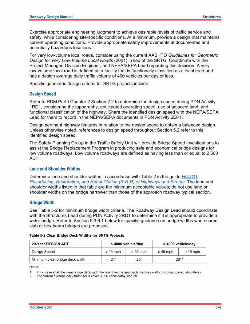
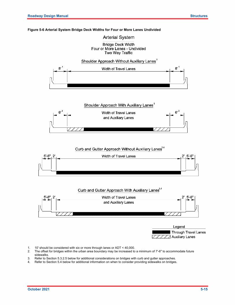
Figure 5-6 Arterial System Bridge Deck Widths for Four or More Lanes Undivided
1. 10' should be considered with six or more through lanes or ADT < 40,000. 2. The offset for bridges within the urban area boundary may be increased to a minimum of 7'-6" to accommodate future
sidewalks. 3. Refer to Section 5.3.2.5 below for additional considerations on bridges with curb and gutter approaches. 4. Refer to Section 5.4 below for additional information on when to consider providing sidewalks on bridges.
Roadway Design Manual Structures
October 2021 5-16
Figure 5-7 Collector Roads and Streets Bridge Deck Widths for Two-Lane Two-Way Traffic
1. The width of traveled way may remain at 22' on reconstructed highways where alignment and safety records are satisfactory. 2. For bridges in excess of 100' in length, the minimum width of traveled way plus 3' on each side is acceptable. 3. An 18' minimum width may be used for roadways with ADT < 250 and speed of 40 mph or less. 4. With speeds of 55 mph or greater, consider using lane width of 24' where substantial truck volumes are present or agricultural
equipment frequently uses the road. 5. Bridge deck width charts are based on design year ADT. If only current ADT is available, design year ADT should be obtained
from the traffic forecasting unit of the statewide planning branch. 6. Where the approach roadway width (traveled way plus shoulder) is surfaced, that surface width shall be carried across all
structures. 7. Refer to GB Chapter 3 for curve widening consideration. 8. The offset for bridges within the urban area boundary may be increased to a minimum of 7'-6" to accommodate future
sidewalks. The engineer should check with the hydraulics unit to determine if additional offset is needed to accommodate for drainage.
9. Refer to Section 5.3.2.5 below for additional considerations on bridges with curb and gutter approaches. 10. When auxiliary lanes are required, add their width to the width of the travel lanes. 11. Minimum shoulder widths of 6' are desired for structures which are located at interchanges. The minimum values shown above
may be used if the required sight distance can be achieved.
Roadway Design Manual Structures
October 2021 5-17
Figure 5-8 Local Roads and Streets Bridge Deck Widths
1. The width of traveled way may remain at 22' on reconstructed highways where alignment and safety records are satisfactory. 2. For bridges in excess of 100' in length, the minimum width of traveled way plus 3' on each side is acceptable. 3. For mountainous terrain and having an ADT between 400 and 600 the use of 18' width and 2' shoulders is acceptable. Refer to
GB Chapter 5. 4. With speeds of 55 mph or greater, consider using lane width of 24' where substantial truck volumes are present or agricultural
equipment frequently uses the road. 5. Bridge deck width charts are based on design year ADT. If only current ADT is available, design year ADT should be obtained
from the traffic forecasting unit of the statewide planning branch. 6. Refer to GB Chapter 3 for curve widening consideration. 7. The offset for bridges within the urban area boundary may be increased to a minimum of 7'-6" to accommodate future
sidewalks. The engineer should check with the hydraulics unit to determine if additional offset is needed to accommodate for drainage.
8. Refer to Section 5.3.2.5 below for additional considerations on bridges with curb and gutter approaches. 9. When auxiliary lanes are required, add their width to the width of the travel lanes. 10. Minimum shoulder widths of 6' are desired for structures which are located at interchanges. The minimum values shown above
may be used if the required sight distance can be achieved.
Roadway Design Manual Structures
October 2021 5-18
Figure 5-9 Local and Collector System Bridge Deck Widths for Four or More Lanes Divided
1. Minimum shoulder widths of 6' are desired for structures which are located at interchanges. The minimum values shown above may be used if the required sight distance can be achieved.
2. For structures of 100' or less in length and having ADT over 2,000 use 6' shoulders. 3. For structures of 100' or less in length and having ADT over 8,000 use 4' shoulders. 4. The offset for bridges within the urban area boundary may be increased to a minimum of 7'-6" to accommodate future
sidewalks. 5. Review Section 5.3.2 in its entirety for additional information on medians across bridges. 6. Refer to Section 5.3.2.5 below for additional considerations on bridges with curb and gutter approaches. 7. Refer to Section 5.4 below for additional information on when to consider providing sidewalks on bridges.
Roadway Design Manual Structures
October 2021 5-19
Figure 5-10 Local and Collector System Bridge Deck Widths for Four or More Lanes Divided with Auxiliary Lanes
1. Minimum shoulder widths of 6' are desired for structures which are located at interchanges. The minimum values shown above may be used if the required sight distance can be achieved.
2. For structures of 100' or less in length and having ADT over 2,000 use 6' shoulders. 3. For structures of 100' or less in length and having ADT over 8,000 use 4' shoulders. 4. The offset for bridges within the urban area boundary may be increased to a minimum of 7'-6" to accommodate future
sidewalks. 5. Review Section 5.3.2 in its entirety for additional information on medians across bridges. 6. Refer to Section 5.3.2.5 below for additional considerations on bridges with curb and gutter approaches. 7. Refer to Section 5.4 below for additional information on when to consider providing sidewalks on bridges.
Roadway Design Manual Structures
October 2021 5-20
Figure 5-11 Local and Collector System Bridge Deck Widths for Four or More Lanes Undivided Two-Way Traffic
1. Minimum shoulder widths of 6' are desired for structures which are located at interchanges. The minimum values shown above may be used if the required sight distance can be achieved.
2. For structures of 100' or less in length and having ADT over 2,000 use 6' shoulders. 3. The offset for bridges within the urban area boundary may be increased to a minimum of 7'-6" to accommodate future
sidewalks. 4. Refer to Section 5.3.2.5 below for additional considerations on bridges with curb and gutter approaches. 5. Refer to Section 5.4 below for additional information on when to consider providing sidewalks on bridges.
Roadway Design Manual Structures
October 2021 5-21
Figure 5-12 One Way Ramp Bridge Deck Widths
1. Use 10' for directional interchange ramps. On directional interchange ramps it is acceptable to switch the widened offset to the inside of the curve when needed for horizontal sight distance.
2. Curb and gutter should be considered only to facilitate particularly difficult drainage situations. Curb and gutter is not recommended on intermediate or directional ramps, except in special cases.
3. Refer to GB Chapter 10 for additional information.
Note that the 2-foot gutter widths shown in these guidelines assume the use of standard 2′-6′′ curb and gutter details. If other curb and gutter details are used, adjust bridge widths accordingly.
Roadway Design Manual Structures
October 2021 5-22
5.3.2.2 Single versus Dual Bridges On a divided highway, coordinate with the Project Manager, Structures Lead, and Work Zone Traffic Control (WZTC) Project Design Engineer during PDN Activities 2RD1, 2TM2, and 2ST1 to determine whether to provide dual, separate structures or a single structure. Consider bridge constructability and future bridge inspection access. Generally, the Structures Management Unit prefers dual, separate bridges when the clear space in the median between the edges of the bridge decks is wide enough to facilitate future bridge inspections. Ideally, the clear median between structures should be wide enough to allow access by under bridge inspection devices (also known as snoopers); however, in cases where other means of access are possible, a narrower clear median width may be acceptable. Consider the concept temporary traffic control plans; the phasing of construction and associated traffic shifts may suggest advantages to the use of a single structure or dual, separate structures. If a single structure is proposed, show the raised median or median barrier width in the DRPS. From a geometry and design perspective is it most desirable to provide a uniform median width and a single vertical alignment through the roadway approaches and along the structure. If dual, separate bridges are proposed, previous value engineering exercises suggest that providing independent alignments and independent vertical profiles (also known as bifurcated profiles) allows flexibility for optimizing earthwork, retaining walls, vertical clearances, maintenance of existing pavement, and structure type and size. In some cases, local adjustments to the horizontal or vertical alignments at bridges (including widening or narrowing of median offsets) may allow for structure designs that are safer, easier, and/or more economical to build and maintain. Coordinate with the Project Manager, Structures Lead, WZTC Project Design Engineer, Area Construction Engineer, and Division staff when considering local horizontal or vertical alignments at bridges. Consider current, proposed, and future conditions when making such evaluations.
5.3.2.3 Raised Islands on Bridges Coordinate with the Structures Lead during PDN Activity 2RD1 to determine if a raised island is required on a bridge. When raised islands are required, use only mountable island types. Section 6.2.5 of the NCDOT Structures Management Unit Manual and NCDOT Roadway Standard Drawings Std. No. 852.01 include standard details for standard mountable islands (also known as permanent concrete median strips) on bridge decks. Detail islands in the DRPS.
5.3.2.4 Median Barriers Coordinate with the Structures Lead during PDN Activity 2RD1 to determine if a median barrier is required on the bridge. Provide a concrete median barrier in these situations:
• Single structures on controlled access facilities regardless of design speed
• Single structures on non-controlled divided facilities with design speeds greater than 50 mph
Where the approach roadway has a concrete median barrier, continue the same type of barrier across the structure. If there is no concrete median barrier on the approach roadway, provide the standard concrete median barrier recommended in Figures 6-27 and 6-28 of the NCDOT Structures Management Unit Manual; locate the ends of barrier at the ends of approach slab and provide appropriate safety end treatments.
5.3.2.5 Special Criteria for Facilities with Sidewalks, Bikeways, Shared-Use Paths Design the clear width for new bridges on streets with curb and gutter approaches to match the curb-to-curb approach width except where bikeways are carried across the structure. For projects involving bikeways, determine the required clear width on a case-by-case basis. Determine bridge deck widths during PDN Activity 2RD1 based on the functional classification, traffic conditions (ADT), and the widths and types of lanes of the roadway being carried by the bridge.
5.3.3 Horizontal Clearances for Bridges Horizontal clearance requirements under a highway bridge affect bridge span lengths and total length. Identify the minimum horizontal clearance requirements for the feature or features being crossed by the bridge.
5.3.3.1 Bridges over Roadways Determine horizontal clearance requirements for bridges crossing existing or proposed roadways during PDN Activity 2RD1 based on the functional classification, traffic conditions (ADT), and the widths and types of lanes of the roadway or roadways under the bridge. Coordinate with the Project Manager, Structures Lead, Congestion Management Project Design Engineer, NEPA/SEPA Lead, and appropriate Division staff to consider accommodating future widening of the roadway under the bridge. Any provisions for future widenings other than those contained in the approved environmental documents prepared in PDN Activity 2EP1 shall require approval by the Project Manager and the Division Engineer. The typical sections under the bridge should reflect the approved Design Criteria (PDN Activity 2RD1) and approved Traffic Analysis (PDN Activity 2TM1). Refer to Figures 5-13 through 5-19 for illustrations of the appropriate horizontal clearance requirements for bridges crossing Interstate highways, Freeways, Arterial System roads, Local and Collector roads, and Ramps. When a ditch section is to be continued under a bridge, coordinate with the Structures Lead and the Hydraulic Design Engineer during PDN Activity 2RD1 and adjust the roadway typical section under the bridge as appropriate to avoid conflicts between ditches and interior bents. Ideally, provide 2-foot minimum clearance between the face of interior bent columns and the top of the ditch. During PDN Activity 2RD1, the Structures Lead will evaluate the feasibility of the initial structure concept proposed by the roadway designer. The Structures Lead will determine the necessity for, and location of, interior bents, considering construction cost, maintenance cost, risk of accidents, potential for future widening (of both the bridge itself and the roadway underneath the bridge), and continuity of the typical section under the bridge. Provide input on these items to the Structures Lead as appropriate. If necessary, adjust the typical section under the bridge to accommodate interior bents or other structural features, with appropriate horizontal clearance provisions. During PDN Activity 2RD1, coordinate with the Project Manager, Division Project Manager, Division Traffic Engineer, Division Project Development Engineer, Division Environmental Supervisor, and Division Planning Engineer to determine the necessity for providing sufficient lateral offset to allow for construction of future greenways, sidewalks, or trails where the NCDOT Complete Streets Policy guidelines has justified the need for additional lateral offset. Depict such offsets in the typical section under the bridge so the Structures Lead can address these requirements when laying out the bridge.
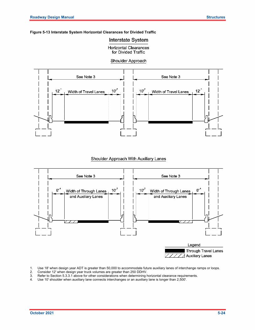
Figure 5-13 Interstate System Horizontal Clearances for Divided Traffic
1. Use 18' when design year ADT is greater than 50,000 to accommodate future auxiliary lanes of interchange ramps or loops. 2. Consider 12' when design year truck volumes are greater than 250 DDHV. 3. Refer to Section 5.3.3.1 above for other considerations when determining horizontal clearance requirements. 4. Use 10' shoulder when auxiliary lane connects interchanges or an auxiliary lane is longer than 2,500'.
Roadway Design Manual Structures
October 2021 5-25
Figure 5-14 Freeway System Horizontal Clearances for Divided Traffic
1. Use 18' when design year ADT is greater than 50,000 to accommodate future auxiliary lanes of interchange ramps or loops. 2. Consider 12' when design year truck volumes are greater than 250 DDHV. 3. Refer to Section 5.3.3.1 above for other considerations when determining horizontal clearance requirements. 4. Use 10' shoulder when auxiliary lane connects interchanges or an auxiliary lane is longer than 2,500'.
Roadway Design Manual Structures
October 2021 5-26
Figure 5-15 Arterial System Horizontal Clearances for Undivided Traffic
1. When design ADT is under 2,000 use 6' offset. When design ADT is 2,000 and over, use 8' offset. 2. The offset for bridges within the urban area boundary may be increased to a minimum of 7'-6" to accommodate future
sidewalks. Engineer should check with the Hydraulics Unit to determine if additional offset is needed to accommodate for drainage.
3. Refer to Section 5.3.3.1 above for other considerations when determining horizontal clearance requirements. 4. Refer to Section 5.3.7 below for additional information on sidewalks and curb and gutter approaches. The presence of curb and
gutter does not negate the need to provide protection when bridge piers are located within the clear zone.
Roadway Design Manual Structures
October 2021 5-27
Figure 5-16 Arterial System Horizontal Clearances for Divided Traffic Shoulder Approach
1. The offset for bridges within the urban area boundary may be increased to a minimum of 7'-6" to accommodate future sidewalks. Engineer should check with the Hydraulics Unit to determine if additional offset is needed to accommodate for drainage.
2. Refer to Section 5.3.3.1 above for other considerations when determining horizontal clearance requirements.
Roadway Design Manual Structures
October 2021 5-28
Figure 5-17 Arterial System Horizontal Clearances for Divided Traffic Curb and Gutter Approach
1. Refer to Section 5.3.3.1 above for other considerations when determining horizontal clearance requirements. 2. Refer to Section 5.3.7 below for additional information on sidewalks and curb and gutter approaches. The presence of curb and
gutter does not negate the need to provide protection when bridge piers are located within the clear zone.
Roadway Design Manual Structures
October 2021 5-29
Figure 5-18 Local and Collector System Horizontal Clearances for Design Year ADT
1. The offset for bridges within the urban area boundary may be increased to a minimum of 7'-6" to accommodate future sidewalks. Engineer should check with the Hydraulics Unit to determine if additional offset is needed to accommodate for drainage.
2. Refer to Section 5.3.3.1 above for other considerations when determining horizontal clearance requirements. 3. Refer to Section 5.3.7 below for additional information on sidewalks and curb and gutter approaches. The presence of curb and
gutter does not negate the need to provide protection when bridge piers are located within the clear zone.
Roadway Design Manual Structures
October 2021 5-30
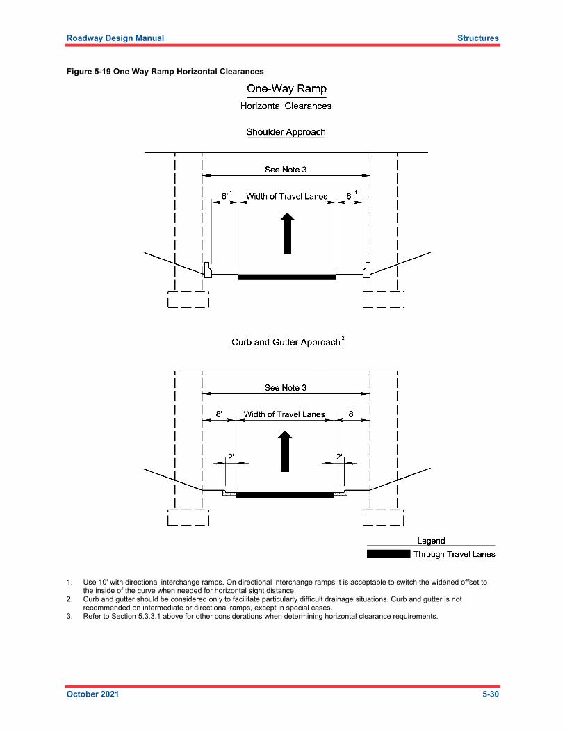
Figure 5-19 One Way Ramp Horizontal Clearances
1. Use 10' with directional interchange ramps. On directional interchange ramps it is acceptable to switch the widened offset to the inside of the curve when needed for horizontal sight distance.
2. Curb and gutter should be considered only to facilitate particularly difficult drainage situations. Curb and gutter is not recommended on intermediate or directional ramps, except in special cases.
3. Refer to Section 5.3.3.1 above for other considerations when determining horizontal clearance requirements.
Roadway Design Manual Structures
October 2021 5-31
5.3.3.2 Bridges over Waterways Determine the required length of bridges crossing existing or proposed waterways (such as streams, rivers, lakes, canals, or flood relief channels) based on the Hydraulic Planning Report prepared by the Hydraulic Design Engineer in PDN Activity 2HY1. Collaborate with the Structures Lead and Hydraulic Design Engineer as needed to determine an economical and practical bridge length and identify appropriate interior bent locations during PDN Activity 2RD1. Coordinate with the Project Manager, Structures Lead and appliable governing agencies (such as the U.S. Coast Guard or U.S. Army Corps of Engineers) on a case-by-case basis to identify bridge length, horizontal navigation clearance, and interior bent location requirements for bridges crossing navigable waterways during PDN Activity 2RD1.
5.3.3.3 Bridges over Railroads Determine the required length of bridges crossing existing or proposed railroads during PDN Activity 2RD1. Collaborate with the Structures Lead and Project Manager as needed to determine an economical and practical bridge length and identify appropriate interior bent locations during PDN Activity 2RD1. In general, provide 25 feet of horizontal clearance from centerline of track to face of bent (to avoid the need for crash walls); in most cases this will meet the roadbed standards for most railroads and will provide room for a ditch in front of the bent. For bridges over railroads owned by North Carolina Railroad (NCRR), CSX, or Norfolk Southern Railroad, refer to the railroad owner’s standards for additional guidance. For bridges over railroads owned by CSX (and as general good practice for bridges over any railroads) avoid locating mechanically stabilized earth (MSE) walls or other movement-activated retaining walls within the railroad right of way. Adjust these requirements to reflect individual site conditions as requested by the railroad. The Project Manager, Roadway Design Lead, and Structures Lead should coordinate with the affected railroads at the beginning of PDN Activity 2RD1 to confirm the requirements. Present the confirmed requirements in the DRPS.
5.3.3.4 Bridge End Bent Slopes Coordinate with the Project Manager, Structures Lead, and Design Geotechnical Engineer during PDN Activity 2RD1 to determine the end bent slopes. In some cases, vertical abutment walls are provided at bridge end bents to reduce span lengths and the total length of the bridge. Such cases typically involve the use of mechanically stabilized earth (MSE) walls or other retaining wall types. Coordinate with the Project Manager, Structures Lead, and Design Geotechnical Engineer during PDN Activity 2RD1 when vertical walls are considered at end bents. Consider structural issues, geotechnical issues, safety issues (such as sight distances), and future widening issues. Generally, bridges are provided with spill-through slopes at end bents. When spill-through slopes are provided at end bents, required end bent slopes (generally either 1.5:1 or 2:1 (horizontal : vertical), measured normal to the end bent) are defined in Section 11-1 of the NCDOT Structures Management Unit Manual, however in some cases site-specific conditions may require the use of nonstandard slopes. For bridges over roadways and railroads (except where project specific requirements dictate otherwise), the Structures Lead will generally detail 4-inch-thick end bent concrete slope protection.
For bridges over roadways when the end bent fill slope is 2:1 (normal to the end bent), the Structures Lead typically details end bent concrete slope protection to the limits of the shadow line of the bridge per the provisions of Section 12-5 of the NCDOT Structures Management Unit Manual. For bridges over roadways when the end bent fill slope is 1.5:1 (normal to the end bent), the Structures Lead typically details end bent concrete slope protection until the slopes are 1.75:1 or flatter. For bridges carrying roadways on fills, use a conical (wrap around) transition from the slope under the bridge to the side slopes, where the side slopes are 2:1 or flatter. In this case end bent concrete slope protection is provided until the midpoint of the transition from the end bent fill slope (normal to the end bent) to the approach embankment side slopes; the slope at this midpoint should be 1.75:1 or flatter. Section 12-5 of the NCDOT Structures Management Unit Manual includes figures showing the end bent concrete slope protection limits for various situations. For bridges over water, the Structures Lead will generally detail rock rip-rap slope protection at end bents in accordance with the Bridge Survey and Hydraulic Design Report (prepared by the Hydraulic Design Engineer during PDN Activity 2HY1) and the provisions of Section 12-4 of the NCDOT Structures Management Unit Manual. Coordinate with the Structures Engineer, Design Geotechnical Engineer, and Hydraulic Design Engineer during PDN Activity 2RD1 to determine the required slope protection for bridges over water. For bridges with large skew angles, there may be no slope transition in two opposing quadrants of the crossing. In this case, the 1.5:1 end bent slope will simply intersect the flatter end bent fill slope. Slope paving transitions will vary from bridge to bridge depending upon skew angle, type of grading around the bridge, pier placement, and the type of structure (single or dual). Coordinate with the Structures Engineer during PDN Activity 2RD1 to determine slope protection details at each bridge site. This coordination facilitates development of the bridge Preliminary General Drawings to enable the correct detailing in the roadway plans for paved shoulder tapers, placement of concrete barrier or guardrail, and roadway shoulder and ditch transitions on the bridge approach. Typically, end bent concrete slope protection (pay item 4″ SLOPE PROTECTION) and rock riprap at end bents (pay item RIP RAP CLASS II (1′-6″ THICK) or similar) are Structures pay items and are not included in the roadway estimate. For nontypical situations (such as concrete slope protection or rock riprap at locations extending beyond the typical bridge end bent locations), coordinate with the Structures Lead to determine pay items and details for the final plans.
5.3.4 Vertical Clearances for Bridges Design vertical geometry to provide adequate vertical clearance for structures crossing roadways. Meet minimum vertical clearance requirements above the full width of pavement including useable shoulder and minimum vertical clearance requirements above future lanes and future loops. Present vertical clearance requirements (including needed accommodations for future lanes) in the DRPS. Identify the bridge control point as part of the vertical geometry design process. The bridge control point is the horizontal location of the point at which the minimum vertical clearance occurs. Identify the bridge control point by considering the relationship between the vertical profiles and typical sections (cross slopes and superelevations) of the roadways on and below the bridge. In many cases, the bridge control point can be clearly identified based on the interaction of profiles and cross slopes, but in other cases the bridge control point may change through the course of the development of the vertical geometry design. Examine crown points,
shoulder break points, and other changes in cross-sectional geometry as possible bridge control point locations. Examine these points on both the left and right sides of the alignments on and below the bridge. Once identified, use the bridge control point to help set vertical profiles such that minimum vertical clearance requirements are met. After designing the vertical profiles and cross-sectional geometry, confirm that minimum vertical clearance requirements are met at all possible locations of the bridge control point to check that the actual point of minimum vertical clearance has been correctly identified.
5.3.4.1 Required Vertical Clearances Minimum vertical clearance requirements for highway bridges over various roadways and railroads are presented in Table 5-3. The minimum required clearance values include an allowance for 6 inches of future resurfacing. The desirable clearance values include an additional 6 inches to provide the flexibility to accommodate minor changes to final superstructure depths without redesign of the roadway geometry.
Table 5-3 Vertical Clearances for Highway Bridges
Element Crossed Minimum Required Clearance
Desirable Clearance Notes
Interstate Highways, Freeways, and Arterials
16′-6″ 17′-0″ Structures over roadways with flexible (asphalt) pavements
Interstate Highways, Freeways, and Arterials
17′-0″ 17′-6″ Structures over roadways with Portland cement concrete pavement
Interstate Highways, Freeways, and Arterials
17′-0″ 17′-6″ Structures over roadways with pavement type not yet determined in the design process, with ADTT > 5,000
Local and Collector Roads and Streets
15′-0″ 15′-6″
Railroads
23′-0″ 23′-6″ Typical clearance requirements are shown; coordinate with affected railroad at the beginning of PDN Activity 2RD1 to confirm.
Vertical clearances significantly greater than these limits require justification by economics or by reason of the vertical geometry being controlled by other design features. For highway bridges over railroads, the typical minimum required vertical clearance is 23′-0″ and the desired vertical clearance is 23′-6″. However, the roadway designer, Project Manager, and Structures Lead should confirm the minimum required vertical clearance with the affected railroad at the beginning of PDN Activity 2RD1 and present the confirmed requirements in the DRPS. For pedestrian overpass bridges and sign structures, the minimum required vertical clearance is 17′-0″ and the desired vertical clearance is 17′-6″. Freeboard (minimum vertical clearance from water surface elevation to bridge superstructure low chord elevation) shall be at least 2 feet for bridges carrying Interstate highways, Freeways, Arterials, or Secondary crossings over major rivers. Freeboard shall be at least 1-foot for other roads. Freeboard less than these limits can be discussed on a case-by-case basis when conditions warrant, if approved by the Hydraulic Design Engineer, the Structures Lead, and any affected stakeholder agencies (such as the FHWA, the U.S. Army Corp of Engineers, the FEMA, or other agencies).
Roadway Design Manual Structures
October 2021 5-34
Identify vertical navigation clearance requirements for bridges over navigable waterways based on the U.S. Coast Guard Bridge Permit or based on agreements with the affected governing agencies or organizations.
5.3.4.2 Bridge Superstructure Depths NCDOT Structures Management Unit Manual Figure 6-1 provides a list of preliminary superstructure depths for span lengths up to 160 feet. Preliminary superstructure depths for span lengths greater than 160 feet are estimated by the Structures Lead on a case-by-case basis. Coordinate with the Structures Lead during PDN Activity 2RD1 to determine appropriate span arrangements, span lengths, and preliminary superstructure depths. Use the longest span length within a given bridge when determining preliminary superstructure depths and consider using the next larger depth when the controlling span length is near the upper end of the design span range. Use these preliminary superstructure depths to check preliminary vertical clearances during PDN Activity 2RD1 (refer to Section 5.3.4.1 above). The Structures Lead will confirm the preliminary superstructure depth during PDN Activity 2ST1 and will confirm the final superstructure depth during PDN Activity 3ST1. To meet vertical clearance requirements, the roadway designer may need to revise roadway profiles to accommodate revisions to the superstructure depth.
5.3.5 Geometric Design Considerations at Bridges Coordinate the geometric design of the roadway at bridges with the Structures Lead early during PDN Activity 2RD1. Discuss the geometric design with regard to the guidelines presented below. When possible, adjust the geometric design of the roadway to simplify the design, detailing, and construction of the bridges. When considering the use of geometry not satisfying the ideal recommendations below, consult with both the Structures Lead and the Area Construction Engineer.
5.3.5.1 Horizontal Alignment Horizontal alignments with spiral curves greatly complicate the design, detailing, and construction of bridges. Avoid locating spiral curves on bridges whenever possible; balance this preference with other considerations such as minimizing right of way impacts. Avoid locating circular curves on bridges if possible. When impractical to completely avoid horizontal curvature on the bridge, locate the begin and end points of the curve (PC and PT point) outside of the begin and end of the bridge if possible. When the bridge end bents are skewed, check that the acute corners of the bridge remain within the limits of the circular curve if possible. When practical, adjust alignments to reduce or eliminate skew of the alignment being carried by the bridge in relation to the roadway or other features being crossed below. The Structures Lead may choose to reduce or eliminate the skew of end bents or interior bents by lengthening the bridge or by other means. Combinations of curvature and skew greatly complicate the design, detailing, and construction of bridges. Avoid such geometry or minimize the severity as much as possible.
5.3.5.2 Vertical Alignment In general, design the vertical profile over a bridge to provide a tangent grade or a crest vertical curve and avoid locating sag vertical curves on bridges, particularly when the bridge superstructure uses prestressed concrete girders. Prestressed concrete girders feature upward
camber at midspan and require deeper than normal girder build-ups when the roadway geometry involves a sag vertical curve; this complicates design, detailing, and construction of the bridge. Do not locate low points on bridges, as this results in unacceptable ponding on the structure. Providing deck drains does not alleviate the ponding; deck drains at low points are particularly susceptible to clogging by sediment and debris. When designing the vertical profiles over and under a bridge, consider the need to meet vertical clearance requirements. Refer to Section 5.3.4 above for further discussion of vertical clearances and the bridge control point. For divided highways with separate, dual bridges: Consider designing with independent vertical profiles (also known as bifurcated profiles) when warranted by the nature of the design. Example situations might include conditions where it is desirable to have different left lane and right lane profiles to better match local topography or to better tie into driveways or cross streets near the ends of the bridge. In such situations, exercise engineering judgment and locate grade points on the appropriate alignments. Coordinate with the Structures Lead during PDN Activity 2RD1 to discuss how the roadway design will affect the design and construction of the bridges. For divided highways with single bridges: Design a single vertical profile with the grade point at centerline of alignment.
5.3.5.3 Cross Slopes, Superelevation, and Cross-Sectional Geometry In general, provide a constant cross-sectional geometry across the length of the bridge when feasible. Avoid superelevation transitions on bridges, as this complicates deck screeding. Avoid transitioning from a crown section to a superelevated section on bridges if possible; such a transition cannot be accommodated by common bridge deck screeding machines, forcing the use of specialty longitudinal deck screed machines and complicated deck placement operations. Other limits on cross slopes and superelevation are presented in Sections 6.2.2.7, 6.4.1, and 6.5.1 of the NCDOT Structures Management Unit Manual. There are several limits which, if exceeded, might render the structure extremely difficult, impractical, or impossible to construct. Coordinate with the Structures Lead during PDN Activity 2RD1 to review and discuss the cross slopes, superelevation, and cross-sectional geometry at all bridges on the project. When designing divided highways, coordinate with the Structures Lead and the Area Construction Engineer during PDN Activity 2RD1 to discuss the location of the grade point(s). Generally, design with grade points located on the roadway surface; choose between providing a single grade point on the median centerline versus providing split grade points based on conversations with the Structures Lead and the Regional Bridge Construction Engineer, the nature of the bridge (i.e., one single bridge versus separate dual bridges), and the implications on cross-sectional geometry
5.3.5.4 Geometric Feature Combinations to Avoid In addition to the items listed above, the NCDOT Structures Management Unit Manual notes that combinations of two or more of the following geometric features can result in bridge deck surfaces that are difficult to finish with typical bridge deck screeding machines.
• Crowned section (e.g., normal crown) Avoid combinations of these conditions on bridges. If it appears combinations of these conditions are unavoidable, discuss the implications with the Structures Lead and the Regional Bridge Construction Engineer.
5.3.6 Guidelines for Cored Slab and Box Beam Bridge Spans Prestressed concrete cored slabs and box beams represent a practical and economical superstructure choice for small, short length bridges in some, but not all, situations. Section 6.1.2 of the NCDOT Structures Management Unit Manual lists functional classification, highway system, bridge length, span length, horizontal and vertical geometry, cross slopes, superelevation, and other cross-sectional geometry limits, and other considerations for the use of prestressed concrete cored slabs and box beams. Consult with the Structures Lead (and the Hydraulic Design Engineer if the bridge is a stream crossing) during PDN Activity 2RD1 to determine if cored slabs or box beams are a practical choice any given bridge site. Various limitations and guidelines related to the use of cored slabs and box beams are listed below. If these limits are exceeded, the use of cored slabs or box beams can still be considered on a case-by-case basis, subject to approval by the Project Manager, Division Engineer, Regional Bridge Construction Engineer, and Structures Management Unit.
5.3.6.1 Cored Slab and Box Beam Bridge Widths Cored slabs and box beams are 3-foot-wide elements constructed side-by-side and post-tensioned together. As a result, the available out-to-out bridge widths vary by 3-foot increments. Increase the shoulder widths as needed on the bridge so that the sum of lane, shoulder, median, sidewalk, and barrier widths equals a 3-foot increment. Coordinate with the Structures Lead to determine the width of barrier rails (including consideration of offsets from back face of barrier to edge of bridge deck as prescribed in Section 6.2.4 and the associated figures in the NCDOT Structures Management Unit Manual).
5.3.6.2 Cored Slab and Box Beam Bridge Wearing Surfaces Sections 6.4.3 and 6.5.3 of the NCDOT Structures Management Unit Manual specify the desired wearing surface (overlay) material (asphalt or concrete) for cored slab and box beam bridges, respectively, based on highway system, anticipated traffic volumes, and specific site conditions (such as low water crossings in some parts of the state). Consult with the Structures Lead during PDN Activity 2RD1 to determine the appropriate wearing surface material and the minimum wearing surface thickness. Cored slab and box beam superstructures are constructed in such a way that they provide a single cross slope at the top of the prestressed concrete elements. Crown sections roadway geometry is achieved by varying the thickness of the overlay across the width of the bridge. Superelevated roadway geometry is achieved by constructing the cored slab or box beam superstructure on a cross slope (with sloped end bent and interior bent caps). Superelevation transition is achieved by varying the thickness of the wearing surface across the width and length of the bridge. Avoid situations that require excessive wearing surface thickness to achieve the desired roadway geometry. Coordinate with the Structures Lead to determine the nominal wearing surface thickness for cored slab or box beam bridges. Consider the roadway profile, cross slope, upward camber at midspan of the cored slabs or box beams, and minimum permissible overlay thickness.
Determine the nomination overlay thickness at the span ends so that the minimum permissible overlay thickness is provided at midspan.
5.3.6.3 Cored Slab and Box Beam Bridge Standard Designs Coordinate with the Structures Lead during PDN Activity 2RD1 to discuss how the roadway design can accommodate the use cored slab and box beam standard design plans if possible. The standard plans are given for skews between 60 degrees and 120 degrees at increments of 15 degrees. Span lengths are given at 5-foot increments in Table 5-4.
Table 5-4 Standard Design Cored Slab and Box Beams Parameters
Span Length in 5′ Increments Unit Depth Type Superstructure Depth at
Gutter line (see note)
25′ to 55′ 21″ Cored Slab 25″
60′ to 70′ 24″ Cored Slab 28″
75′ to 90′ 33″ Box Beam 37″
95′ to 100′ 39″ Box Beam 43″
Note: Superstructure depth is from top of wearing surface to bottom of prestressed concrete cored slab or box beam, measured at the gutter line. These values include a 2″ allowance for the wearing surface and a 2″ allowance for adjustment of the wearing surface thickness to accommodate camber of the cored slab or box beam at midspan. Adjust (increase) the values as appropriate to account for cross slope effects, especially for crown sections. In crown sections, the wearing surface at centerline of alignment is typically thicker than at the gutter line, so the effective superstructure depth used to calculate vertical clearances will be larger.
5.3.6.4 Top-Down Construction of Cored Slab and Box Beam Bridge Cored slab and box beam units can be used when top-down construction is anticipated or required. Coordinate with the Project Manager, NEPA/SEPA Lead, and Structures Lead during PDN Activity 2RD1 to discuss the use of top-down construction. Sections 6.4.2 and 6.5.2 of the NCDOT Structures Management Unit Manual lists maximum span length limits for top-down construction of cored slab and box beam superstructures, respectively.
5.3.6.5 Cored Slab and Box Beam Bridge Geometry Sections 6.4.1 and 6.5.1 of the NCDOT Structures Management Unit Manual list various limits on horizontal alignment, skew, vertical curve, and superelevation or normal crown geometry for cored slab and box beam bridges, respectively. Among other considerations listed in these references, limit superelevation on cored slab or box beam bridges to 4 percent or less.
5.3.7 Grading and Roadside Design Under Bridges During the Alignment Defined Stage and PDN Activity 2RD1, the roadway designer is responsible for coordinating with the other technical discipline leads, NCDOT Units, and Division staff as appropriate to develop the Design Recommendation Plan Set. During this stage, the Structures Lead will be developing Preliminary General Drawings as part of PDN Activity 2ST2. Coordinate with the Structures Lead, Hydraulic Design Engineer, and Design Geotechnical Engineer during PDN Activity 2RD1 to determine appropriate grading and roadside design at bridges. Discuss roadside safety, drainage, slope stability, structural design, and economy.
Drainage Under Bridges Several factors affect drainage under bridges, including:
• Roadway and ditch grades
• Type of grading (cut or fill)
• Single or dual lane roadway
• End bent fill area treatment Normally, there should be only a small amount of water under a bridge, except in unusual situations such as:
• Combinations of divided roadway sections and large bridge skew angles
• Cases where collected drainage from the roadway below the bridge is carried through the section under the bridge.
In some cases, special shoulder paving may be required to prevent erosion at the point where concentrated water runs from behind the concrete barrier onto the shoulder.
Layout and Design of Bridges The layout and design of bridges involves determining span lengths, end bent and bent locations, the types and sizes of superstructure elements, the types and sizes of substructure elements, and the types and sizes of foundations. The Structures Lead and the Design Geotechnical Engineer will address the layout and design of bridges, which is affected by various factors, including:
• Span lengths
• Total bridge length
• Vertical clearance requirements
• Skew
• Curvature
• End bent slopes
End Bent Slopes End bent slopes are generally determined to achieve a measure of slope stability, which is affected by:
• Local subsurface conditions
• Embankment heights
• Type of grading (cut or fill) In some cases, retaining wall end bents may be used instead of end bent slopes.
Grading at Bridges Evaluate each bridge on a case-by-case basis with regard to drainage under the bridge, layout of the bridge, and end bent slopes. Once these items are determined, there are various options for grading at bridges, as well as various options for protecting bridge piers and end bent
Roadway Design Manual Structures
October 2021 5-39
slopes. Grading and roadside design issues at bridges typically fall into one of nine basic situations. Four situations address protection of bridge piers, either in the median or adjacent to shoulders:
1. Median bridge piers with earth berms 2. Median bridge piers with concrete barrier or guardrail 3. Outside or shoulder bridge piers within the clear zone 4. Outside bridge piers beyond the clear zone
Treat retaining walls within the clear zone in a manner like outside or shoulder bridge piers within the clear zone. Five situations address protection of end bent slopes without shoulder bridge piers:
1. End bent slopes with natural or false cuts 2. End bent slopes with concrete barrier or guardrail 3. End bent slopes with curb and gutter 4. End bent slopes with existing ditch (without provision for future pavement widening) 5. End bent slopes with existing ditch (with provision for future pavement widening)
Each of these situations is described below in Sections 5.3.7.1 through 5.3.7.9, respectively. Section 5.3.7.10 discusses shoulder slope rates under bridges; this information applies to the various situations discussed in Sections 5.3.7.1 through 5.3.7.9. Section 5.3.3.4 discusses the geometry of bridge end bent slopes; this information applies to the various situations discussed in Sections 5.3.7.1 through 5.3.7.9.
5.3.7.1 Median Bridge Piers with Earth Berms Provide earth berm median pier protection when structures span over divided facilities with bridge piers located in medians of sufficient width to accommodate the required grading. Coordinate with the Structures Lead during PDN Activity 2RD1 to determine the need for, and location of, median bridge piers. Assess median width and clear zone requirements with respect to the traffic volumes and conditions of the facility under the bridge. Provide a minimum 400-foot-long transition between the normal typical section and the slope protection required at the bridge pier. Develop grading details and transitions from the typical section in accordance with NCDOT Roadway Standard Drawings Std. No. 225.08. When the median width is not sufficient to accommodate the required grading, provide concrete barrier; refer to Section 5.3.7.2 below.
5.3.7.2 Median Bridge Piers with Concrete Barrier or Guardrail Provide concrete barrier or guardrail pier protection when structures span over divided facilities with bridge piers located in medians of width insufficient to accommodate the required grading. Coordinate with the Structures Lead during PDN Activity 2RD1 to determine the need for, and location of, median bridge piers. Assess median width and clear zone requirements with respect to the traffic volumes and conditions of the facility under the bridge. Refer to NCDOT Roadway Standard Drawings Std. No. 857.01 and 862.01 for guidance on the use of concrete barrier versus guardrail and Std. No. 854.05 for concrete barrier transition lengths and details.
Note that the presence of curb and gutter does not negate the need to provide protection when median bridge piers are located within the clear zone.
5.3.7.3 Outside or Shoulder Bridge Piers Within the Clear Zone The Structures Lead will determine the need for, and location of, outside bridge piers (i.e., interior bents located between the bridge end bents and the roadway below the bridge) during PDN Activity 2RD1. The use of shoulder bridge piers (i.e., interior bents located directly adjacent to the shoulders of the roadway below the bridge) is discouraged, but in some cases may be required. Section 6.1.2 of the NCDOT Structures Management Unit Manual states that shoulder bridge piers are not permitted adjacent to the travel way. When outside or shoulder bridge piers are required, they may be located within the clear zone. Refer to RDM Part I Chapter 4 Section 4.6 for guidance on defining the clear zone. Measure the horizontal clearance to the face of the bridge pier, which is defined as the element of the bridge pier (the column or bent cap) closest to the travel way. In cases where very tall columns are used (where the bottom of the bent cap is located several feet above the desired minimum vertical clearance), measure the horizontal clearance to the column; otherwise measure the horizontal clearance to the face of the bent cap. Compare the clear zone width and the horizontal clearance to the face of the bridge pier. When bridge piers are located within the clear zone, provide appropriate protection. Refer to RDM Part I Chapter 6 for guidance on roadside barrier design. Typical protection measures include concrete barrier or guardrail; see below for further discussion of specific details related to these two options. Note that the presence of curb and gutter does not negate the need to provide protection when median bridge piers are located within the clear zone.
Outside Bridge Piers with Concrete Barrier When using concrete barrier protection, locate the end bent slope break point 1′-6′′ behind the face of the barrier. This is based on the 1′-5″ width of the NCDOT Standard 41-inch tall Single Faced Precast Reinforced Concrete Barrier (NCDOT Roadway Standard Drawings Std. No. 857.01) with a 1-inch expansion joint between the back of barrier and the face of the turned-down toe of the 4-inch thick end bent concrete slope protection. If a wider rail is used, provide a larger dimension. The end bent slope break point is defined as the intersection of the projection of the top of the paved offset with the projection of the top of the end bent concrete slope protection. Coordinate with the Structures Lead during PDN Activity 2ST1 to locate the bridge pier a minimum of 1′-11′′ behind the face of the barrier. This results in a 6-inch space between the back of the barrier and the face of the pier allowing room for the turned-down toe of the 4-inch end bent concrete slope protection with 1-inch expansion joints on both sides. The space provided will allow runoff from the end bent concrete slope protection to flow unobstructed behind the concrete barrier. Detail a full width paved shoulder from the edge of travel lane to the face of the concrete barrier. Taper the full width paved shoulder under the bridge to the typical paved shoulder width as shown in the plan view in NCDOT Roadway Standard Drawings Std. No. 610.01. Develop grading details and transitions from the typical section in accordance with NCDOT Roadway Standard Drawings Std. No. 225.09. When the concrete barrier section extends beyond the end of slope protection paving, begin the paved shoulder taper at the end of concrete barrier.
Refer to NCDOT Roadway Standard Drawings Std. No. 610.01 for further details. See also Figure 5-20 for additional information not explicitly presented in Std. No. 610.01.
Outside Bridge Piers with Guardrail When using guardrail protection, locate the end bent slope break point at least 5′-6″ from the face of the guardrail when standard steel beam guardrail (6′-3″ post spacing with 6-foot posts) is specified. The minimum offset distance from the face of the guardrail to the end bent slope break point is 3′-6″ (3′-1.5″ post spacing with 6-foot posts). When the offset distance from the end bend slope break point to face of guardrail is between 3′-6″ and 5′-6″, specify 3′-1.5″ post spacing at a point 25 feet prior to the outside bridge pier and carry the 3′-1.5″ post spacing throughout the length of the outside bridge piers. If the offset distance of 3′-6″ cannot be provided, use concrete barrier protection. Add a special detail or notes on the guardrail summary and plan sheets to clarify the areas where 3′-1.5″ post spacing is required. Refer to NCDOT Roadway Standard Drawings Std. No. 862.01 for further details.
Figure 5-20 Shoulder Detail Under Bridge with Bridge Pier and Concrete Barrier or with End Bent Slope and Guardrail
1. The location of the projected end bent break point for the case of a bridge pier on outside shoulder is the same as for the case of guardrail on outside shoulder.
2. Refer to Figures 5-13 thru 5-19 above related to Horizontal Clearances.
Roadway Design Manual Structures
October 2021 5-43
5.3.7.4 Outside Bridge Piers Beyond the Clear Zone The Structures Lead will determine the need for, and location of, outside bridge piers (i.e., interior bents located between the bridge end bents and the roadway below the bridge) during PDN Activity 2RD1. In some cases, the outside bridge pier closest to the roadway may be located beyond the clear zone. These situations are typically associated with very long, multi-span bridges. The face of bridge pier is defined as the closest element of the bridge pier (whether column or bent cap). In cases where very tall columns are used (where the bottom of the bent cap is located several feet above the desired minimum vertical clearance), measure the horizontal clearance to the face of the bent cap. In these situations, the location of the end bent slope break point is typically determined by the Structures Lead based on the required location of the end bent and the end bent fill slope. The location of the end bent in these cases may be influenced by minimum hydraulic opening criteria, the need to clear subsurface obstructions, or other governing constraints. Develop grading details and transitions from the typical section in accordance with NCDOT Roadway Standard Drawings Std. No. 225.09.
5.3.7.5 End Bent Slopes with Natural or False Cuts Coordinate with the Structures Lead during PDN Activity 2RD1 to confirm whether a shoulder bridge pier or outside bridge pier is required. Refer to Section 5.3.7.3 or Section 5.3.7.4 if a shoulder or outside bridge pier is required. If a shoulder or bridge pier is not required, and if the approach roadway is in a cut section, provide a natural cut slope. Refer to Section 11-1 of the NCDOT Structures Management Unit Manual for the grade of the end bent slope (1.5:1, 2:1, or other). Transition the natural cut slope to the end bent slope as appropriate if they are different; refer to NCDOT Roadway Standard Drawings Std. No. 225.07 as a guide for transition dimensions. If a shoulder or bridge pier is not required, and if the approach roadway is in a fill section, then determine whether to provide a false cut or not.
• When the roadway under the bridge is part of an Interstate, Freeway, or Expressway system, provide a false cut.
• When the roadway under the bridge is part of a Local or Collector system, provide a false cut only if suitable waste material is available.
Discuss the decision to provide a false cut with the Project Manager and Structures Lead during PDN Activity 2RD1. Refer to NCDOT Roadway Standard Drawings Std. No. 225.07 for false cut details and Section 11-1 of the NCDOT Structures Management Unit Manual for the grade of the end bent slope (1.5:1, 2:1, or other). If a natural or false cut is provided, the projected end bent slope break point is defined as the intersection of the projection of the top of the paved offset with the projection of the top of the end bent concrete slope protection. Coordinate with the Structures Lead to determine the location of the bridge end bents such that adequate horizontal clearance for the roadway below and the grade of the end bent slopes meets the provisions of Section 5.3.3 above. The Structures Lead may also choose to extend the span length slightly for economical or other reasons. Round the end bent fill slope with a 6-foot vertical curve. Provide 6-inch concrete slope protection, extending 4′-6′′ to either side of the projected end bent slope break point. This 6-inch
concrete slope protection is a Roadway pay item (pay item 6″ SLOPE PROTECTION). The 4-inch end bent concrete slope protection (pay item 4″ SLOPE PROTECTION) beyond the 4′-6′′ distance is a Structures pay item. Provide a full width paved shoulder between the edge of the travel lane and the beginning of the 6-inch concrete slope protection. Taper the full width paved shoulder under the bridge to the typical paved shoulder width as shown in the plan view in NCDOT Roadway Standard Drawings Std. No. 610.03. Refer to NCDOT Roadway Standard Drawings Std. Nos. 225.07 and 610.03 for additional details, including grading details and transitions from the typical section. See also Figure 5-21 for additional information not explicitly presented in Std. Nos. 225.07 and 610.03. Refer to RDM Section 5.3.7.6 below if a natural or false cut is not provided.
Figure 5-21 Shoulder Detail Under Bridge with 6-Inch Slope Protection or Abutment Wall
1. The location of the projected end bent break point for the case of a 6" slope protection with a 6' vertical curve is the same as for the case of an abutment wall.
2. Refer to Figures 5-13 thru 5-19 above, related to Horizontal Clearances.
Roadway Design Manual Structures
October 2021 5-46
5.3.7.6 End Bent Slopes with Concrete Barrier or Guardrail Protect the end bent slope with concrete barrier or guardrail when:
• the location of the grade separation bridge end bents is controlled by the need to provide adequate horizontal clearance for the roadway below.
• shoulder bridge piers are not provided
• a natural or false cut is not provided Concrete barrier is generally the preferred method of protection as it typically requires less long-term maintenance when subjected to multiple impact incidents. However, the use of guardrail can be considered on a case-by-case basis. Coordinate with Division personnel, considering anticipated crash rates, initial construction cost funding, maintenance costs, aesthetics, and the presence of features within the recovery areas outside of the clear zone. Refer to NCDOT Roadway Standard Drawings Std. Nos. 610.01 and 610.02 for guides for paving shoulders under bridges with concrete barrier and guardrail, respectively. The end bent slope break point is in the same position whether concrete barrier or guardrail is used. Locate the end bent slope break point 1-inch behind the back of the concrete barrier or the guardrail. The end bent slope break point is defined as the intersection of the projection of the top of the paved offset with the projection of the top of the end bent concrete slope protection. The geometry of the end bent concrete slope protection and its toe wall will be the same whether concrete barrier or guardrail is used and is the same as discussed in Section 5.3.7.3 above. Extend the shoulder paving from the edge of travel lane to the slope protection paving. Taper the full width paved shoulder under the bridge to the typical paved shoulder width as shown in the plan view in NCDOT Roadway Standard Drawings Std. Nos. 610.01 or 610.02 as appropriate. Also refer to Figure 5-20 for additional information not explicitly presented in Std. Nos. 610.01 and 610.02. Refer to NCDOT Roadway Standard Drawings Std. No. 225.09 for a guide for shoulder and ditch transitions at grade separations.
5.3.7.7 End Bent Slopes with Curb and Gutter When a curb and gutter section is carried beneath a bridge, locate the end bent slope break point a minimum of 1-inch behind the back of the curb, edge of the sidewalk or shared-use path to allow for a 1-inch expansion joint between it and the toe of the 4-inch concrete slope protection (Figure 5-22). Coordinate with the Project Manager and appropriate agencies or other disciplines to identify the need for, and widths of, any sidewalks or shared-use paths. If outside bridge piers are used, locate the face of pier a minimum of 5 inches behind the end bent slope break point.
1. Consider the width of the curb and gutter, sidewalk (if any), and other offsets (if any) on a case-by-case basis in determining the appropriate width in each location. Barrier or guardrail may be warranted depending on the clear zone requirements of the roadway.
2. Refer to Figures 5-13 thru 5-19 above related to Horizontal Clearances.
Roadway Design Manual Structures
October 2021 5-48
5.3.7.8 End Bent Slopes with Existing Ditch (without Provision for Future Pavement Widening) Follow these guidelines when a proposed bridge will be built over an existing road with no proposed changes in the pavement, shoulder, or ditch of the road beneath the bridge, and no provisions to accommodate future widening of the road under the bridge. Locate the end bent slope break point to satisfy the applicable provisions of RDM Section 5.3.3.3 above for the given facility being crossed by the bridge. The end bent slope break point is defined as the intersection of end bent fill slope with the projection of the shoulder slope from the edge of existing pavement. Coordinate with the Structures Lead during PDN Activity 2RD1 to determine if outside bridge piers will be required. If an outside pier is needed, locate the face of the bridge pier a minimum of 5′-0″ behind the end bent slope break point. If the face of the pier in this location is at least 2′-0″ behind the existing ditch, the ditch should drain satisfactorily. If the face of the pier in this location is less than 2′-0″ behind the existing ditch such that the pier would interfere with flow of water in the ditch, consider the following options:
1. Slightly grade the shoulder and ditch section to allow drainage to flow past the pier. 2. Eliminate the existing ditch, grade to the shoulder section and install concrete barrier
or guardrail and a drainage system for the bridge end bent area. 3. Discuss locating the pier further from the ditch with the Structures Lead.
5.3.7.9 End Bent Slopes with Existing Ditch (with Provision for Future Pavement Widening) Follow these guidelines when a proposed bridge will be built over an existing road with minor pavement widening and/or shoulder and ditch grading proposed initially, and with provisions for additional pavement widening in the future. Determine bridge widths and clearances based on the traffic volumes, design speed, and bridge recommendations developed during the Project Initiation Phase under PDN Activity 1RD1. Coordinate with the Project Manager, Division Engineer, and Roadway Design Unit before implementing any provisions for future widening beyond than those noted in the Record of Decision prepared under PDN Activity 2EP1. Locate the end bent slope break point to satisfy the applicable provisions of RDM Section 5.3.3.3 above for the given facility being crossed by the bridge. The end bent slope break point is defined as the intersection of end bent fill slope with the projection of the future shoulder slope from the edge of existing pavement. Coordinate with the Structures Lead during PDN Activity 2RD1 to determine if outside bridge piers will be required. If an outside pier is needed, locate the face of the bridge pier a minimum of 5′-0″ behind the end bent slope break point. If the face of the pier in this location is at least 2′-0″ behind the existing ditch, the ditch should drain satisfactorily. If the face of the pier in this location is less than 2′-0″ behind the existing ditch such that the pier would interfere with flow of water in the ditch, consider the following options:
1. Slightly grade the shoulder and ditch section to allow drainage to flow past the pier. 2. Eliminate the existing ditch, grade to the shoulder section and install concrete barrier
or guardrail and a drainage system for the bridge end bent area. 3. Discuss locating the pier further from the ditch with the Structures Lead.
Roadway Design Manual Structures
October 2021 5-49
5.3.7.10 Shoulder Slopes Under Bridges See Figure 5-23 for guidance on shoulder slope rates and rollover when the roadway under a bridge is superelevated. The figure shows shoulder slope treatment for both the high-side and low-side for superelevation rates of .00 to .10. Apply the left side of Figure 5-23 in the following cases:
• No paved shoulder.
• 4-foot paved shoulder.
• 10-foot paved shoulder. Apply the right side of Figure 5-23 when providing a 2-foot full depth paved shoulder.
Roadway Design Manual Structures
October 2021 5-50
Figure 5-23 Standard Method of Shoulder Construction Under Bridges
1. Roll-over algebraic difference in rate of cross slope not to exceed 0.06 as shown. 2. Transition from above slope under bridge to roadway typical section within 100' from edge of bridge slope protection.
Roadway Design Manual Structures
October 2021 5-51
This shoulder treatment under bridges agrees with NCDOT Roadway Standard Drawings Std. Nos. 560.01 and 560.02 with the following exception: Do not provide the 6-inch thick slope protection with 6-foot vertical curve (per NCDOT Roadway Standard Drawings Std. No. 610.03) on the high side of superelevation at the bridge end bent fill. Instead, maintain a constant slope in the shoulder up to the end bent slope break point. The Structures Lead should extend the bridge end bent concrete slope protection and provide the turned down toe at the end bent slope break point. Provide a 100-foot-long transition in shoulder slope approaching and leaving the bridge area in cases where the typical roadway shoulder has the vertical curve on the high side of superelevation.
5.3.8 Bridges Approaches
5.3.8.1 Bridge Approach Slabs Provide concrete approach slabs at the ends of all bridges. Sections 8.2.2 and 8.2.3 of the NCDOT Structures Management Unit Manual present bridge approach slab length and width requirements, respectively. Bridge approach slab lengths are determined based on functional classification and anticipated ADT of the facility; in some cases, longer approach slabs may be used on a case-by-case basis if suggested by local site conditions and Division preference. Bridge approach slab widths are affected by the gutter-to-gutter width on the bridge, the presence or absence of sidewalks, the type of barrier rail and end treatments used on the bridge, and curb widths as appropriate. The NCDOT Structures Management Unit Manual also provides guidance regarding the geometry of the ends of approach slabs. The type of approach roadway pavement (flexible or rigid pavement) and Division preference typically determine whether the ends of approach slabs will be parallel to the bridge end bent fill faces or normal to the roadway alignment. Coordinate with the Structures Lead and Division staff during PDN Activity 2RD1 and Activity 2ST1 to determine bridge approach slab lengths, widths, and geometry. If the width of approach slab differs from the width of the approach roadway traffic lanes and paved shoulders, provide paved shoulder tapers using a 25:1 taper geometry (Figure 5-24).
5.3.8.2 Bridge Approach Fills Provide bridge approach fills at all bridges. Coordinate with the Structures Lead and Design Geotechnical Engineer during PDN Activity 2RD1 to determine which standard approach fill detail to use at each bridge, or if a special approach fill detail is needed. NCDOT Roadway Standard Drawings Std. Nos. 422.01, 422.02, and 422.03 show standard bridge approach fill details. See Table 5-5 for typical usage of the standard bridge approach fill details.
Table 5-5 Typical Usage of Standard Bridge Approach Fill Details
Roadway Standard Drawing No.
Bridge Approach Fill Type
Typical Usage
422.01 Type I – Standard Approach Fill
Bridges with end spans composed of steel or prestressed concrete girders and conventional end bents
422.02 Type II – Modified Approach Fill
Bridges with end spans composed of cored slabs or box beams and conventional end bents
422.03 Type A – Alternate Approach Fill for Integral Abutment
Bridges with integral abutments
422D10 Type III – Reinforced Approach Fill
Bridges with mechanically stabilized earth (MSE) walls at conventional end bents. See Note.
Note: MSE wall fill details provided by the Design Geotechnical Engineer or Structures Lead, or both.
5.3.8.3 Bridge Barrier Rail End Treatments Provide bridge barrier rail end treatments in accordance with guidance in RDM Part I Chapter 6 Section 6.3. Coordinate with the Structures Lead during PDN Activity 2RD1 to determine appropriate bridge barrier rail end treatments at both ends of bridges on the project. In general, two types of guardrail end units are available for the construction of new bridges.
1. Use Type III guardrail end unit to anchor guardrail to bridges with metal bar railing or other barrier rail types with a vertical face allowing the Type III attachment.
2. Use Type B-77 guardrail end unit to anchor guardrail to bridges with F-shape barrier rail. The end unit has a rub rail which prevents vehicles from snagging the barrier.
Refer to NCDOT Roadway Standard Drawings Std. No. 862.03 for details of both the Type III and Type B-77 guardrail end units. Show required guardrail attachment points in the DRPS.
5.3.8.4 Unpaved Approach Roadways On low volume, unpaved roads, provide an approved asphalt surfacing for a distance of 100 feet from each end of newly constructed bridges. Design the paved travel lane to be 20 feet wide and transition to match the deck width of the bridge over a distance of 10 feet from the end bent fill face. Refer to Section 5.2.3 above for guardrail requirements.
5.3.9 Attachments to Bridges
5.3.9.1 Lighting Structures Management Unit policy generally discourages the mounting of lighting on bridges. In general, lighting should be supported using separate, ground-mounted structures.
Occasionally, under bridge lighting is required under very wide structures. Small luminaires can be attached to bridge interior bents if coordinated early in the design process. Occasionally, bridge deck lighting may be required for projects with high pedestrian traffic and/or aesthetic requirements. Coordinate with the Project Manager, Roadway Lighting Design Engineers, and Structures Lead during PDN Activity 2RD1 to discuss the need for, design of, and location of, such lights and their supports. Develop details on a case-by-case basis. Do not mount high mast lighting on bridges.
5.3.9.2 Fencing Occasionally, project requirements may dictate the need to provide fencing on bridges; common situations include pedestrian bridges or highway bridges with sidewalks over railroads or highways, particularly when high volumes of pedestrian traffic are anticipated. Coordinate with the Project Manager and Structures Lead during PDN Activity 2RD1 to discuss the need for, design of, and limits of fencing on bridges. The Structures Lead can develop fencing details on a case-by-case basis. The roadway designer shall coordinate with the Structure Lead to facilitate the tie of any roadway fencing to the structure fence.
5.3.10 Barrier Rails and Sidewalks Coordinate with the Structures Lead during PDN Activity 2RD1 to determine what type of barrier railings will be used on each bridge. Consider functional classification, design speeds, the presence of sidewalks, bikeways, or shared-use paths, and any project-specific criteria, commitments, or requirements. Section 6.2.4 (and associated figures) of the NCDOT Structures Management Unit Manual presents standard bridge barrier railings and associated guidance. Coordinate the use of non-standard bridge barrier railings with the Structures Management Unit. Refer to Section 5.4 for further discussion of bikeways and share-use paths on bridges.
5.4 Structures in Multimodal Facilities The NCDOT Complete Streets Policy directs the Department to consider and incorporate several modes of transportation when building new projects or making improvements to existing infrastructure. Evaluate the incorporation of pedestrian, bicycle, and public transportation facilities in all transportation projects. Coordinate with the Project Manager, Integrated Mobility Division, and NEPA/SEPA Lead during PDN Activity 1TM1 to determine what features to incorporate into the design of the project. Coordinate with the Project Manager and Structures Lead during PDN Activities 2RD1, 1ST1, 2ST1, and 2ST2 to communicate requirements that affect the design and detailing of bridges and structures. Examples of pertinent coordination items include providing horizontal clearance under bridges to accommodate proposed or future sidewalks, bikeways, or shared-use paths, and providing separate pedestrian bridges or pedestrian culverts. Refer to RDM Part I Chapter 2 Section 2.6 for additional guidance related to the NCDOT Complete Streets Policy and the design of projects to incorporate multimodal facilities. Coordinate with the Project Manager, NEPA/SEPA Lead, and Structures Lead during PDN Activity 2RD1 to determine whether to provide sidewalks on bridges. Consider providing sidewalks on new bridges with curb and gutter approach roadways on facilities without control of access. In some instances, only one side of a bridge may warrant a sidewalk. Do not provide sidewalks on bridges in controlled access facilities. When deciding whether to provide sidewalks on bridges, consider commitments made in NEPA/SEPA documents. Section 6.2.5 (and associated figures) of the NCDOT Structures Management Unit Manual provides standard
details for typical sidewalks and barrier rails on bridges. The typical detail for a sidewalk on a bridge is 5′-6″ wide, comprised of a 5′-0″ sidewalk and a 6-inch-wide curb section. Coordinate with the Structure Lead when a sidewalk or shared-use path wider than 5′-0″ is required. Consider cross slopes when developing interface geometry. Slope the top of sidewalk to drain toward the curb regardless of the cross slope of the travel way and shoulders. Provide barrier rail with a minimum height of 4′-8″, measured from top of sidewalk or other riding/walking surface to top of rail. If necessary, the Structures Lead can develop custom details for unique project-specific situations. Generally, provide sidewalk, bikeway, or shared-use paths on or under bridges with the same width as provided in the approaches. Provide a barrier rail between vehicle lanes or shoulders and sideways, bikeways, or shared-use paths when appropriate. Consider the needs of pedestrians and bicyclists when designing guardrail on bridge approaches. Attach guardrail to the face of the bridge barrier, behind the sidewalk, bikeway, or shared-use path. Transition the alignment of the guardrail as far away from the vehicle zone as conditions permit. For roads with shoulder approaches the minimum offset from the edge of the vehicle zone to the face of the guardrail is 4′-0″. When designing sidewalks, bikeways, or shared-use paths under bridges or in pedestrian culverts, consider the following:
• Overall length
• The need for internal lighting
• Pathway grade
• Sight distances
• Approaching pathway alignment
• Drainage
• Ease of maintenance
• Open designs which allow daylight and lighting from the outside Coordinate with the Project Manager, Structures Lead, Integrated Mobility Division, and NEPA/SEPA Lead during PDN Activity 1TM1 to discuss required clear pathway widths (and heights) for dedicated pedestrian or shared-use bridges, culverts, or tunnels. Consider the need to accommodate service vehicles as appropriate.
5.5 Retaining Walls 5.5.1 Types of Retaining Walls Most retaining walls are either fill walls or cut walls. Fill walls are generally constructed from the bottom up by placing fill material behind the wall. Cut walls are generally constructed from the top down by removing cut material from in front of the wall.
5.5.1.1 Fill Walls The most common types of fill walls are (1) gravity retaining walls, (2) mechanically stabilized earth (MSE) retaining walls, and (3) cantilever concrete retaining walls.
Roadway Design Manual Structures
October 2021 5-56
Using one of these wall types in a cut wall application typically involves extensive overexcavation and significant temporary construction impacts. Avoid using these wall types in cut wall applications.
1. Gravity Retaining Walls – Gravity retaining walls are typically short walls (exposed heights of 10 feet or less) that develop stability from their own weight or mass. The most common types of gravity walls are cast-in-place gravity retaining walls, segmental gravity retaining walls and precast gravity retaining walls.
a. Cast-in-place gravity retaining walls are constructed of cast-in-place unreinforced concrete and in accordance with NCDOT Roadway Standard Drawings Std. No. 453.01 and Section 453 of the NCDOT Standard Specifications for Roads and Structures.
b. Segmental gravity retaining walls are constructed of segmental retaining wall units and in accordance with NCDOT Roadway Standard Drawings Std. Nos. 454.01 or 454.02 and Section 454 of the NCDOT Standard Specifications for Roads and Structures.
c. Precast gravity retaining walls are constructed of precast retaining wall units in accordance with Section 455 of the NCDOT Standard Specifications for Roads and Structures.
2. MSE Retaining Walls – MSE retaining walls consist of facing elements connected to layers of soil reinforcement within the retained backfill. For permanent MSE walls, steel or geogrid reinforcements are used with facing elements consisting of precast concrete panels or segmental retaining wall units. For temporary MSE walls, steel, geogrid or geotextile reinforcements are used and facing elements consist of geotextiles and wire forms.
3. Cantilever Concrete Retaining Walls – Cantilever concrete retaining walls are constructed of cast-in-place reinforced concrete connected to a footing. Cantilever concrete walls partially develop their stability from the weight of the backfill over the footing. Cantilever concrete walls are often more expensive than MSE walls and as a result, are normally used only when MSE walls are not feasible. Cantilever concrete retaining walls require large footings extending behind the wall, affecting temporary construction impacts and easements.
For an all-fill wall on existing ground, the existing ground line and bottom of the exposed wall are the same. A permanent underground easement or right of way is required for the MSE reinforcement length or footing width behind the wall. Fill walls can be used in cuts but require either temporary shoring or a temporary slope to construct and may also require additional construction easements.
5.5.1.2 Cut Walls Cut walls can be grouped as either cantilever retaining walls or non-cantilever retaining walls. Cantilever retaining walls are constructed using only vertical elements; they have smaller temporary and permanent easement and right of way impacts, but can only accommodate limited wall heights. Non-cantilever retaining walls use tie backs or anchors to provide additional support for the wall; they often can accommodate taller wall heights, but have more significant easement or right of way impacts. The most common types of cantilever cut walls are sheet pile retaining walls and soldier pile retaining walls.
1. Sheet Pile Retaining Walls – Sheet pile retaining walls consist of interlocking sheet piles driven or vibrated into the ground. Sheet pile walls are common for temporary shoring. The Geotechnical Engineering Unit has standard details for temporary sheet pile walls using steel sheet pile sections. Prestressed concrete sheet pile sections have been used in limited applications for permanent retaining walls.
2. Soldier Pile Retaining Walls – Soldier pile retaining walls consist of steel H-piles driven or placed in drilled holes and partially filled with concrete. For permanent soldier pile walls, either precast panels are set in the flanges between adjacent piles, or a cast-in-place reinforced concrete face is connected to the front of the piles. For temporary soldier pile walls, timber lagging is typically set in the flanges between adjacent piles.
The depth of the piles below the bottom of the wall is called the embedment depth. The embedment depth for cantilever cut walls is typically about twice the wall height but is highly dependent on the subsurface conditions and the surrounding geometry (i.e., front and/or back slope). Coordinate with the Design Geotechnical Engineer to determine estimated embedment depths during PDN Activity 2RD1. Use this embedment depth when checking for conflicts with utilities that may run under retaining walls. Cantilever cut walls can be constructed very close to the right of way since no part of the wall extends behind or in front of the wall. These walls can also be used in partial fill situations and usually do not exceed 13 feet in height when standard size H-piles are used (HP 12X53 and HP 14X79). However, the process of installing sheet piles or soldier piles often involves noise and vibration. Coordinate with the Project Manager, Design Geotechnical Engineer, NEPA/SEPA Lead, and Environmental Project Lead when buildings or other nearby features may be adversely affected by noise or vibrations. The most common types of non-cantilever cut walls are (1) soil nail retaining walls and (2) anchored retaining walls.
1. Soil Nail Retaining Walls – Soil nail retaining walls can only be used in cut situations (no fill) and develop stability from passive (non-tensioned) anchors (known as soil nails) that resist applied earth pressure on the wall. Soil nails consist of steel bars grouted in drilled holes inclined at an angle below the horizontal. A soil nail wall consists of soil nails spaced at a regular pattern and connected to a shotcrete and cast-in-place reinforced concrete face with nail heads embedded in the concrete. Shotcrete facing is used for temporary support of the excavation during construction.
2. Anchored Retaining Walls – Anchored retaining walls, also called tieback walls, develop stability from tensioned anchors that resist applied earth pressure on the wall. Anchors consist of steel bars or strands in drilled holes inclined at an angle below the horizontal that are grouted and connected to steel piles. The piles are driven or placed in drilled holes filled with concrete below the bottom of the wall. The face is usually cast-in-place reinforced concrete connected to the piles and timber lagging is typically used for temporary support of the excavation during construction. Anchored walls can be used in partial cut and fill situations, but the anchors do not develop capacity in the unbonded length through the backfill.
For an all cut wall, the grade elevation is either at or above the existing ground line. A permanent underground easement or right of way is required for the nails and anchors behind the wall. Figure 5-25 illustrates a typical retaining wall section. Key components have been labeled and definitions are provided.
Roadway Design Manual Structures
October 2021 5-58
Typical sections of the different types of retaining walls can be found as standard cells on the NCDOT Geotechnical Engineering Unit website. Figure 5-25 Typical Retaining Wall Section
Notes: 1. Bottom of wall - where finished grade (typically cut walls) or existing ground (typically fill walls) intersects front of wall. 2. Wall height - difference between grade elevation and bottom of wall. 3. Wall embedment - difference between bottom of wall and bottom of footing, cast-in-place face, or precast panels. 4. Extension - difference between top of wall and grade elevation. 5. Grade elevation - elevation where finished grade (typically fill walls) or existing ground (typically cut walls) intersects back of wall. 6. Top of wall - top of cast-in-place face of coping (or bottom of cap if abutment wall is part of end bent or embedded in cap). 7. Wall face - exposed face of front of wall. 8. Design height - wall height plus the wall embedment. 9. Final width of ditch to be determined by Hydraulics Unit.
5.5.2 Identification, Layout, and Investigation of Retaining Walls A retaining wall is a structure that retains or holds back a soil or rock mass. Retaining wall applications include repairing landslides, minimizing right of way requirements, shortening bridges (abutment walls), widening roads, and providing property access. Coordinate with the Project Manager, Design Geotechnical Engineer, Structures Lead, Hydraulic Design Engineers, Utility Coordinator, and appropriate Division personnel during PDN Activity 2RD1 to collaboratively evaluate the proposed roadway design for potential locations where using retaining walls could reduce overall project costs or minimize impacts. The specific type of retaining wall employed is dependent on several factors including whether the wall is within a cut or fill section, subsurface conditions in the area around the proposed retaining wall, cost, and aesthetics.
Incorporate potential walls into typical sections, cross sections, and plan sheets and identify potential temporary and permanent impacts to environmentally sensitive areas, historical sites, landmarks, residential communities, or other features. For bridges with vertical abutment walls, the Structures Lead should develop wall envelopes under the PDN Activity 3ST1. The roadway designer and Structures Lead may need to coordinate for abutment walls (walls under bridges) that extend far from the bridge. When considering the use of retaining walls, compare the cost of the retaining wall to the cost of other alternatives. Examples include:
• Minimizing right of way impacts – Compare the cost of retaining walls to the cost of alternatives such as roadway geometry adjustments or the use of reinforced, steepened slopes.
• Reducing bridge costs – Compare the cost of a shorter bridge with wall abutments to the cost of a longer bridge with traditional end bent slopes.
Perform cost comparisons (when appropriate) during Project Initiation, Stage 1, as part of PDN Activity 1ST1 or 1RD1. Retaining wall unit costs vary by application (cut versus fill), wall type, wall height, and subsurface conditions. Coordinate with the Project Manager, Design Geotechnical Engineer, and Structures Lead to determine the feasibility of using retaining walls, appropriate wall types, and applicable unit costs before undertaking a cost comparison study. After confirming proposed wall locations with the Project Manager, transmit the wall locations to the Design Geotechnical Engineer for them to perform retaining wall investigations during PDN Activity 3GT2 phase.
5.5.3 Geometric Design and Protection of Retaining Walls
5.5.3.1 Retaining Wall Alignments Ideally, lay out retaining walls using straight alignments for ease of design and construction. Use curved walls when appropriate to maintain a constant offset from a survey line; note that the minimum permissible radius will vary depending on the type of wall. If a curved wall is specified, coordinate with the Design Geotechnical Engineer prior to preparing the preliminary wall envelope to determine whether a specific wall alignment is feasible. Consider providing each retaining wall with its own unique alignment. Retaining wall alignments are often based on offset alignments from the roadway centerline, but it is not unusual for a retaining wall alignment to be independent of the roadway geometry. Note that for some walls, the stations may be shown on the wall envelope in descending order, since the wall envelope depicts the wall front face (the side of the wall that is exposed).
5.5.3.2 Plan Presentation Present retaining walls on the roadway plans and cross sections. Include preliminary retaining wall information in the DRPS and final retaining wall information in the final plans. When referencing retaining walls on the roadway plans, number each wall sequentially along the -L- alignment (e.g., Retaining Wall #1, Retaining Wall #2). If only one wall is included on a project, identify the retaining wall as Retaining Wall #1. Where retaining walls are opposite each other and begin at the same station, number the wall on the left first. If a retaining wall is located along a -Y- alignment, the numbering sequence shall be based on where the -Y- alignment crosses the -L- alignment. Do not renumber the retaining walls if a wall is added after preliminary wall envelopes are submitted to the Design Geotechnical Engineer.
Roadway Design Manual Structures
October 2021 5-60
Show cast-in-place gravity retaining walls on the cross sections as a graphical element as shown on NCDOT Geotechnical Standard Details Std. No. 453.01. For other wall types, show retaining walls on the cross sections as a graphical element at least 1 foot thick for preliminary layout. Coordinate with the Design Geotechnical Engineer during PDN Activity 2RD1 or sooner to identify the anticipated actual wall thickness, batter, anchors, and other pertinent features, update the graphical representations on the cross sections as appropriate, and investigate for potential conflicts and impacts.
5.5.3.3 Wall Envelopes A wall envelope is a profile view of the exposed wall face area. A wall envelope can be defined as a scaled plot of the grade elevations and bottom of wall elevations, the existing ground elevations (if it intersects the wall) and temporary grade elevations (if applicable) on some frequent station interval along the wall. Provide bottom of wall elevations reflecting a 4-foot wide bench if the finished grade or existing ground in front of the wall is steeper than 6:1 or when directed by the Design Geotechnical Engineer as shown in Figure 5-26. Show the grade and bottom of wall elevations both graphically and numerically. Depict the existing ground line on the envelope, even if it differs from the grade or bottom of wall. These elevations depict whether the wall is a cut wall or a fill wall or a combination of the two. Depict and label the grade and bottom of wall at 50-foot station intervals (e.g., Sta. 10+00, 10+50) along the offset centerline from the beginning to the end of each wall. Where the grade lines are highly variable, the Design Geotechnical Engineer may request the elevations be labeled more frequently. Include calculations of the wall face area with the wall envelope. Develop preliminary wall envelopes during PDN Activity 2RD1 and final wall envelopes during PDN Activity 3RD1. See below for descriptions of each.
Preliminary Wall Envelopes Label the following information on the preliminary wall envelope:
• Station and offset distance at the beginning of wall, end of wall, and where the wall alignment changes (if applicable)
• The grade and bottom of wall elevation at 50-foot station intervals (e.g., Sta. 10+00, 10+50)
Show where the grade elevation intersects the bottom of wall (where the grade and bottom of wall elevations are equal, i.e., where the wall height is null). This will typically occur at the begin and end of each wall. Also show station, offset, grade elevation, and bottom of wall elevation at each point where the wall alignment changes (i.e., at each point where the wall alignment bends). Consider using plus or minus station references (e.g., Sta. 10+12 +/-) to label the estimated beginning and ending of each wall. The Contractor is required to survey the existing ground elevations and submit a revised wall envelope for review and approval prior to designing and constructing each wall. Wall envelopes are typically drawn using an exagerated vertical scale. When walls are not provided with their own unique wall alignment, be aware that wall envelopes may not be depicted accurately in the following situations:
• Walls that do not have a constant offset related to the centerline alignment
For these cases, add the following note to the wall envelope drawing: “THE WALL ENVELOPE DOES NOT ACCURATELY DEPICT THE ACTUAL FACE OF THE WALL.” In these situations, calculate the wall faces areas by hand instead of measuring the areas in the drawing, since the wall envelope drawing presents a distorted view of the wall face. Figure 5-26 shows an example wall envelope.
Roadway Design Manual Structures
October 2021 5-62
Figure 5-26 Example Retaining Wall Envelope Drawing
Roadway Design Manual Structures
October 2021 5-63
Final Wall Envelope Submit a final wall envelope to the Design Geotechnical Engineer during PDN Activity 3RD1, after revising the plans based on input from other discipline leads comments from the combined or final design Field Inspection. Show the same items in the final wall envelopes as were shown in the preliminary wall envelopes. The main differences between the preliminary and final wall envelopes are typically minor changes to the stations and elevations. Note that drainage ditches in the vicinity of the wall may affect the grade elevations on the final wall envelope. Coordinate with the Project Manager, Design Geotechnical Engineer, Hydraulic Design Engineer, WZTC Project Design Engineer, Structures Lead and others as applicable to obtain input prior to preparing the final wall envelopes. Include the final wall envelopes in the retaining wall plans and not the roadway plans, except when there are no structures plans for the project and the retaining wall plans are inserted in the roadway plans as W-series sheets. If a retaining wall is eliminated during the design of the project, include a note in the plans clarifying why the wall numbers are no longer in sequence. Include the note on the plan sheet that depicts the next wall in the series. For example, if Retaining Wall #2 was eliminated, include a note on the plan sheet that contains Retaining Wall #3 stating, “RETAINING WALL #2 HAS BEEN ELIMINATED.” Do not provide such notes when the retaining wall eliminated was the only wall on the project or the wall numbering sequence was not affected.
5.5.3.4 Construction Limits Construction limits to determine right of way or easements vary depending on retaining wall geometry and wall type. Request preliminary retaining wall construction limits from the Design Geotechnical Engineer during PDN Activity 2RD1. The Design Geotechnical Engineer should present final retaining wall construction limits in the roadway foundation recommendations prepared during PDN Activity 3GT2. For cut walls during preliminary design, in the absence of better information from the Design Geotechnical Engineer, right of way or permanent easement approximately 1.2 times the maximum wall height (1.2H) may be shown behind a cut wall in most situations until project specific information is provided. However, for cut walls taller than 15 feet in the coastal plain, contact the Design Geotechnical Engineer as more than 1.2H may be needed for right of way or permanent easement. The coastal plain region is located within Divisions 1-3 and portions of Divisions 4, 6 and 8. For fill walls, assume a preliminary right of way limit at least 5 feet in front of the face of retaining wall.
5.5.3.5 Protection of Retaining Walls If a wall is located within the clear zone, use steel beam guardrail, single-faced reinforced concrete barrier or concrete barrier rail with a moment slab to protect traffic.
Steel Beam Guardrail (Top or Bottom of Wall) Place steel beam guardrail at the bottom or the top of a retaining wall as necessary to protect the hazard. Offset steel beam guardrail 5′-6″ from the face of the guardrail to the nearest wall surface when standard steel beam guardrail (6′-3″ post spacing with 6-foot posts) is specified. The minimum offset distance from the face of the guardrail to the nearest wall surface is 4′-0″ at the top of the wall (6′-3″ post spacing with 8-foot posts) and 3’-6″ at the bottom of the wall (3′-1.5″ post spacing with 6-foot posts). When the offset distance from the wall surface to face of guardrail is between 3′-6″ and 5′-6″ at the bottom of the wall, specify 3′-1.5″ post spacing at a point 25 feet prior to the wall and carry the 3′-1.5″ post spacing throughout the length of the wall. If the offset distance at the bottom of the wall is less than 3′-6″, specify single-faced concrete
Roadway Design Manual Structures
October 2021 5-64
barrier. Add a special detail or notes on the guardrail summary and plan sheets to clarify the areas where 3′-1.5″ post spacing and extra depth 8-foot posts are required. Coordinate with the Design Geotechnical Engineer to investigate whether guardrail posts conflict with the retaining wall design. Figure 5-27 illustrates the offset requirements for steel beam guardrail in relation to the wall. Figure 5-27 Offsets for Steel Beam Guardrail at Retaining Walls
1. Use concrete barrier rail with moment slab if offset is less than 4′. 2. Specify 3′-1.5″ post spacing when the offset distance at the bottom of the wall is between 3′-6″ and 5′-6″.
Concrete Barrier Rail with Moment Slab (Top of Wall Only) If the offset distance from the face of the guardrail to the top of a retaining wall is less than 4 feet, provide a concrete barrier rail with moment slab. Locate concrete barrier rail with moment slab on top of the wall with no offset as illustrated in Figure 5-28. When concrete barrier rail with moment slab is required, coordinate with the Design Geotechnical Engineer and Structures Lead to confirm design details and identify pay items (Concrete Barrier Rail is a Structures pay item). Due to its relatively high cost, use a concrete barrier rail with moment slab only when other options, such as moving the wall far enough from the travel way to allow the use of steel beam guardrail, are not possible or are less economical. Include details for the concrete barrier rail with moment slab with the retaining wall plans. Coordinate with the Design Geotechnical Engineer to obtain the most current standard details for concrete barrier with moment slab. Attach guardrail to the concrete barrier rail with appropriate anchors per the most current guardrail policies. If guardrail is attached to the concrete barrier rail, extend the barrier the entire length of the wall. Concrete barrier rail with moment slab is not designed to accommodate pedestrian traffic adjacent to the barrier rail. If sidewalk is proposed adjacent to the concrete barrier rail,
Roadway Design Manual Structures
October 2021 5-65
coordinate with the Design Geotechnical Engineer and Structures Lead, who will assess the associated loading on the retaining wall and who will design a custom barrier rail with moment slab, respectively. Figure 5-28 Concrete Barrier Rail with Moment Slab on Retaining Wall
Single-Faced Reinforced Concrete Barrier (Bottom of Wall Only) Locate single-faced reinforced concrete barrier next to a wall face when needed at the bottom of a retaining wall. Account for a 1-inch expansion joint between the concrete barrier and the wall. If guardrail needs to be attached to the single-faced concrete barrier, extend the barrier the entire length of the wall. Attach guardrail to the concrete barrier with appropriate anchors per the most current guardrail policies. Figure 5-28 illustrates the placement of single-faced concrete barrier in relation to the bottom of wall. In some cases, the placement of single-faced concrete barrier at the bottom of wall can result in significant cost savings by reducing the wall height (the wall face can be placed closer to the edge of travel lane when concrete barrier is used instead of steel beam guardrail). If future widening is not anticipated in the vicinity of the bottom of the wall, coordinate with the Design Geotechnical Engineer to determine if the use of single-faced concrete barrier will result in cost savings. Include a typical section inset in the roadway plans depicting the placement of the single-faced barrier or guardrail in relation to the retaining wall. Clearly label any proposed offset distances in the inset. When a concrete barrier rail with moment slab is specified, detail asphalt base course (B25.0C) to fill the area between the subgrade and the top of moment slab.
Roadway Design Manual Structures
October 2021 5-66
Fence or Handrail Placement: Provide a fence or handrail when pedestrian traffic is anticipated in the vicinity of the top of a retaining wall. Determine whether handrail or fence is appropriate, based on the height of the wall and the project conditions in the vicinity of the wall. Preferably, locate fence or handrail no closer than 1-foot from the back of wall, and design the fence or handrail posts foundations using standard details. Coordinate with the Design Geotechnical Engineer when providing fence or handrails in the vicinity of a wall to determine if the fence or handrail posts will conflict with the retaining wall design. If it is necessary to locate a fence or handrail directly on a retaining wall, attach the fence or handrail posts to a properly designed cast-in-place concrete structural element (part of the wall or coping). Request the Structures Lead design the proposed details, or use applicable, previously designed, standard details obtained from the State Plans and Standards Engineer in the Contract Standards and Development Unit to prepare details for the attachment to the wall. Incorporate the fence or handrail details into the roadway plans as 2-Series sheets. Show chain link fence that is attached to a retaining wall in the appropriate fence summary and identify it for payment under Section 866 of the NCDOT Standard Specifications for Roads and Structures as Chain Link Fence, ___″ Fabric, per linear foot. Add a label to the fence summary to reference the sheet number (for example: “SEE DETAIL SHEET 2-? FOR FENCE ATTACHMENT TO RETAINING WALL) showing appropriate fence details and sections. Use standard chain link fence symbology to denote the chain link fence on the roadway plans. Use a generic fencing pay item and provide a Special Provision to address payment for handrail that is attached to the wall. Include the handrail in the list of Special Provision items. Consider the maintenance of vegetation when guardrail, fence, or handrails are provided at the top of the wall. Consider providing asphalt or Class A stone for erosion control between the guardrail, fence, or handrail and the retaining wall to reduce the need for maintenance in areas that are difficult to access. Provide a typical section inset or detail showing the asphalt or Class A stone. Coordinate with the Design Geotechnical Engineer during PDN Activity 2RD1 to determine if the presence of vegetation or other erosion control details might affect the design or performance of the retaining wall.
5.5.4 Request for Retaining Wall Design Initiate the request for retaining wall design during PDN Activity 2RD1. Coordinate with the Project Manager, Design Geotechnical Engineer, Hydraulic Design Engineer, and Structure Lead. Allow sufficient time for subsurface investigations and preliminary retaining wall design to occur during PDN Activity 2GT2. Include the following information with the request for retaining wall design:
1. Plan sheet(s), profile sheet(s), and cross sections in the location of the proposed retaining wall(s)
2. Wall plan view(s) with offset centerline(s) and distances and curve data (if applicable)
3. Preliminary wall envelope(s) 4. Other factors that need to be taken into account in the design of the wall(s) (e.g.,
5.5.5 Temporary Shoring Temporary shoring is often required to maintain traffic. On occasion, temporary shoring may be used to protect wetlands, buildings or structures. Temporary shoring is often used during the removal of existing bridges and structures. Refer to the NCDOT Temporary Shoring Memorandum dated January 17, 2007, for additional information regarding various design responsibilities. If temporary shoring is required for maintenance of traffic, show the shoring on the roadway plans, without stationing, in the plan view. Refer to the traffic control plans for the temporary shoring. If temporary shoring is required at more than one location, show the quantity for each location on the traffic control plans. On occasion, the roadway designer will request temporary shoring. In this situation, show the shoring location, including station and offset information, on the roadway plans. Show the typical sections and accompanying notes on the roadway plans. When shoring is required at more than one location, show the quantity for each location on the roadway plans. If temporary shoring is required, the Design Geotechnical Engineer may provide standard shoring details for insertion into the final plans. The number of detail sheets will be dependent on the notes referenced in the Geotechnical Engineering Unit’s standard notes document, NCDOT Temporary Shoring – Shoring Notes. Place the standard shoring details in the roadway plans as 2G Series sheets.
5.6 Sound Barrier Walls The Traffic Noise and Air Quality Group Leader and the Environmental Analysis Project Lead will develop a Final Design Noise Report during PDN Activity 3EN1, providing required locations and limits of proposed sound barrier walls. Additionally, the Final Design Noise Report will include wall envelopes based on proposed grades and the locations of cut/fill sections to establish minimum noise wall heights along the length of any proposed noise wall. Prior to design implementation, review wall locations, limits, and envelopes for constructability, feasibility, utility conflicts, environmental impacts, and roadway design criteria allowances with the Project Manager, Structures Lead, Design Geotechnical Engineer, Hydraulic Design Engineer, NEPA/SEPA Lead, Utility Coordination Project Lead, and any other affected discipline leads. Address wall placement, stations and offsets, and roadside protection at sound barrier walls in the roadway plans. The Structures Lead should prepare sound barrier wall plans using the Sound Barrier Wall (SBW) standard drawings when possible, and custom designs when necessary. The Design Geotechnical Engineer should provide sound barrier wall foundation recommendations. Typically, include SBW plans in the structure plans, except when walls are the only structures on the project; in that event, include the SBW plans in the roadway plans. Show SBWs on the roadway plans and cross sections. When referencing SBWs on the roadway plans, number each wall sequentially along the -L- alignment (for example, “Sound Barrier Wall #1”) with begin and end stations identifying the limits of the proposed SBW. Where SBWs are opposite each other and begin at the same station, number the wall on the left first. If a sound barrier wall is located along a -Y- alignment, the numbering sequence shall be based on where the -Y- alignment crosses the -L- alignment. Coordinate the SBW numbers with the Structures Lead.
Develop the alignment for SBWs shall be using the information provided in the Final Design Noise Report and the Structures Management Unit’s SBW standard drawings. When developing wall alignments, be mindful of the following:
• Consider sight distances; check that appropriate sight distances are provided when are not sufficient; consider changing the SBW alignment or eliminating the SBW.
• Avoid locating SBWs on bridges. If an SBW must be located on a bridge, limit the height to 10 feet or less. Coordinate with the Structures Lead whenever the location of SBWs on bridges is being considered.
• Structures Management Unit’s standard SBW details allow for 10-foot and 15-foot pile spacing. Consider the footprint of SBWs on curved alignments based on chording between the piles when evaluating right of way and clear zone impacts.
• Assume consistent pile spacings the entire length of the wall. Structures Management Unit’s standard SBW details allow for 10-foot and 15-foot pile spacing. When necessary, only use non-standard pile spacings at the ends of the wall or turning points. Do not use pile spacings less than 5 feet.
• Standard precast concrete panels are used with 10-foot or 15-foot pile spacings. Twenty-foot pile spacings are allowed but standard precast panels are not included with the standard drawings. In such cases, the Structures Lead must perform a custom design.
• Structures Management Unit’s standard SBW details show the wall height as the accumulative height of stacked panels, with a minimum embedment depth of 6 inches at the bottom panel.
• Structures Management Unit’s standard SBW details are only appliable for wall heights of 25 feet or less when precast concrete piles are specified, and 29 feet or less when steel piles are specified.
• Walls exceeding 29 feet in height require custom designs. SBWs with heights significantly greater than 29 feet become increasingly impractical from structural design perspective.
• When using precast concrete piles, limit kinks in the wall alignment to angles less than or equal to 45 degrees.
• Changes of more than 1-foot (drop or rise) in the top of wall elevation between panel sections are not permitted, except in the first panel section at either end of the wall. Top of wall elevation changes resulting in a jagged appearance are not allowed.
5.7 Drainage at Bridges 5.7.1 Bridge Deck Drainage Coordinate with the Structures Lead, Hydraulic Design Engineer, and potentially the NEPA/SEPA Lead (for bridges over waterways) during PDN Activities 2RD1, 2ST1, 2ST2, and 2HY1 to address bridge deck drainage. Discuss various options to address excessive spread on bridge decks when predicted by hydraulic design calculations; choose options that best address project needs overall.
Roadway Design Manual Structures
October 2021 5-69
During storm events, drainage runoff can accumulate at the gutter lines on bridges. The width of this runoff accumulation is called the hydraulic spread. Generally, the hydraulic spread should be limited to the shoulders and not extend into the travel lanes. When the width of the hydraulic spread exceeds the width of the shoulders, the design should be adjusted. There are several options for addressing excessive hydraulic spread on bridges:
5. Adjust the vertical profile to improve drainage and reduce hydraulic spread in bridge gutters.
6. Increase bridge deck width to provide wider shoulders to accommodate hydraulic spread.
7. Provide bridge approach drainage to intercept some of the runoff before it reaches the bridge.
8. Provide open drains in the bridge deck at the barrier rail gutter lines. 9. Provide bridge deck drains that feed into a closed drainage system.
Adjusting the vertical profile can reduce the amount of runoff before it reaches the bridge or can accelerate the longitudinal flow of runoff on the bridge (thus reducing the hydraulic spread). In many cases, minor adjustments to the vertical profile can reduce or eliminate excessive hydraulic spread on bridges without adding cost to the project. Increasing bridge deck width to provide wider shoulders on the bridge allows for wider hydraulic spread without impacts to traffic. In some cases, this can reduce or eliminate the need for open deck drains or a closed drainage system. Although the increase in bridge deck width will increase the initial construction cost of the project, the cost increase may be warranted by the reduction in long term maintenance costs associated with a closed drainage system or by the avoidance of open deck drains discharging over environmentally sensitive areas. Bridge approach drainage (i.e., inlets just beyond the bridge approach slabs, at the higher end of the bridge) can intercept much of the runoff prior to it reaching the bridge. This reduces hydraulic spread on the bridge, potentially enough to minimize or avoid the need for bridge deck drains. Drainage inlets are a common feature on highway projects and adding inlets at bridges generally does not significantly increase initial construction costs or long-term maintenance costs. Refer to Section 5.7.2 below for additional discussion of bridge approach drainage.
5.7.2 Bridge Approach Drainage As mentioned in Section 5.7.1 above, providing bridge approach drainage is an effective way of reducing hydraulic spread on bridge decks and thus reducing or eliminating the need to provide bridge deck drains. Coordinate with the Structures Lead and Hydraulic Design Engineer during PDN Activities 2RD1, 2ST1, 2ST2, and 2HY1 to address bridge approach drainage. Choose bridge approach drainage treatments based on the approach roadway conditions. The most common situations include:
5.7.2.1 Roadways with Shoulders Metal funnel drains, grated drop inlets, or concrete bridge approach drop inlets are the most common treatments. Coordinate with the Hydraulic Design Engineer, who will determine which treatment is appropriate.
Roadway Design Manual Structures
October 2021 5-70
5.7.2.2 Curb and Gutter Roadways Coordinate with the Hydraulic Design Engineer, who will determine the specific design and details.