Chapter 6 Lab 6-2, Hot Standby Router Protocol for IPV6 INSTRUCTOR VERSION
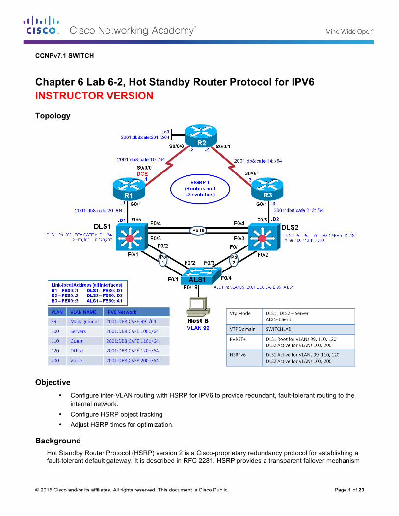
Topology
Objective • Configure inter-VLAN routing with HSRP for IPV6 to provide redundant, fault-tolerant routing to the
internal network. • Configure HSRP object tracking • Adjust HSRP times for optimization.
Background Hot Standby Router Protocol (HSRP) version 2 is a Cisco-proprietary redundancy protocol for establishing a fault-tolerant default gateway. It is described in RFC 2281. HSRP provides a transparent failover mechanism
CCNPv7.1 SWITCH: Lab 6-2, Hot Standby Router Protocol for IPv6
to the end stations on the network. This provides users at the access layer with uninterrupted service to the network if the primary gateway becomes inaccessible. The Virtual Router Redundancy Protocol (VRRP) is a standards-based alternative to HSRP and is defined in RFC 3768. The two technologies are similar but not compatible. This lab focuses on HSRP.
Note: This lab uses Cisco ISR G2 routers running Cisco IOS 15.4(3) images with IP Base and Security packages enabled, and Cisco Catalyst 3560 and 2960 switches running Cisco IOS 15.0(2) IP Services and LAN Base images, respectively. The switches have Fast Ethernet interfaces, so the routing metrics for all Ethernet links in the labs are calculated based on 100 Mb/s, although the routers have Gigabit Ethernet interfaces. The 3560 and 2960 switches are configured with the SDM templates “dual-ipv4-and-ipv6 routing” and “lanbase-routing”, respectively. Depending on the router or switch model and Cisco IOS Software version, the commands available and output produced might vary from what is shown in this lab. Catalyst 3650 switches (running any Cisco IOS XE release) and Catalyst 2960-Plus switches (running any Cisco IOS image) can be used in place of the Catalyst 3560 switches and the Catalyst 2960 switches.
Note(2): This lab's topology is based on the NETLAB Multi-Purpose Academy Pod (MAP). If your classroom is using the standard Cuatro Switch Pod, the PC names may be different than displayed here. Consult with your instructor.
Required Resources • 1 switches (Cisco 2960 with the Cisco IOS Release 15.0(2)SE6 C2960-LANBASEK9-M image or
comparable) • 2 switches (Cisco 3560 with the Cisco IOS Release 15.0(2)SE6 C3560-IPSERVICESK9-M image or
comparable) • Ethernet and console cables • 1 PC
Implement HSRP for IPv6
Step 1: Prepare the switches for the lab
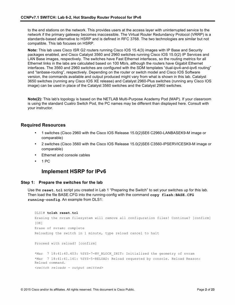
Use the reset.tcl script you created in Lab 1 “Preparing the Switch” to set your switches up for this lab. Then load the file BASE.CFG into the running-config with the command copy flash:BASE.CFG running-config. An example from DLS1:
DLS1# tclsh reset.tcl
Erasing the nvram filesystem will remove all configuration files! Continue? [confirm]
[OK]
Erase of nvram: complete
Reloading the switch in 1 minute, type reload cancel to halt
Proceed with reload? [confirm]
*Mar 7 18:41:40.403: %SYS-7-NV_BLOCK_INIT: Initialized the geometry of nvram
Would you like to enter the initial configuration dialog? [yes/no]: n
Switch> en
*Mar 1 00:01:30.915: %LINK-5-CHANGED: Interface Vlan1, changed state to administratively down
Switch# copy BASE.CFG running-config
Destination filename [running-config]?
184 bytes copied in 0.310 secs (594 bytes/sec)
Step 2: Configure basic switch parameters.
Configure an IP address on the management VLAN according to the diagram. VLAN 1 is the default management VLAN, but following best practice, we will use a different VLAN. In this case, VLAN 99.
Enter basic configuration commands on each switch according to the diagram. Each interface should be configured with a global unicast address and a statically assigned link-local address. Please refer to the table on the topology diagram for the address information.
DLS1 example: DLS1# configure terminal
Enter configuration commands, one per line. End with CNTL/Z.
The interface VLAN 99 will not come up immediately, because the layer 2 instance of the vlan has not yet been defined. This issue will be remedied in subsequent steps.
(Optional) On each switch, create an enable secret password and configure the VTY lines to allow remote access from other network devices.
DLS1 example: DLS1(config)# enable secret class
DLS1(config)# line vty 0 15
DLS1(config-line)# password cisco
DLS1(config-line)# login
Note: The passwords configured here are required for NETLAB compatibility only and are NOT recommended for use in a live environment.
Note(2): For purely lab environment purposes, it is possible to configure the VTY lines so that they accept any Telnet connection immediately, without asking for a password, and place the user into the privileged EXEC mode directly. The configuration would be similar to the following example for DLS1:
DLS1(config)# enable secret class
DLS1(config)# line vty 0 15
DLS1(config-line)# no login
DLS1(config-line)# privilege level 15
Step 3: Configure trunks and EtherChannels between switches.
EtherChannel is used for the trunks because it allows you to utilize both Fast Ethernet interfaces that are available between each device, thereby doubling the bandwidth.
CCNPv7.1 SWITCH: Lab 6-2, Hot Standby Router Protocol for IPv6
Note: It is good practice to shut down the interfaces on both sides of the link before a port channel is created and then re-enable them after the port channel is configured; recall that BASE.CFG shut all interfaces down.
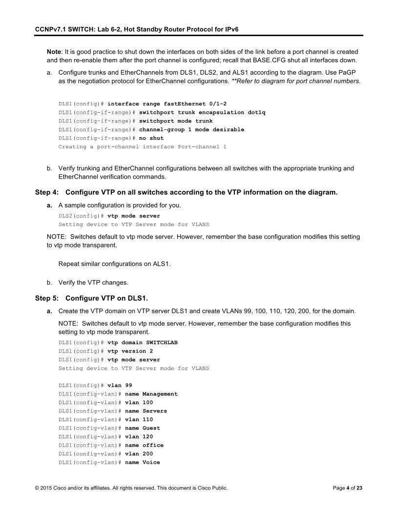
a. Configure trunks and EtherChannels from DLS1, DLS2, and ALS1 according to the diagram. Use PaGP as the negotiation protocol for EtherChannel configurations. **Refer to diagram for port channel numbers.
b. Verify trunking and EtherChannel configurations between all switches with the appropriate trunking and EtherChannel verification commands.
Step 4: Configure VTP on all switches according to the VTP information on the diagram.
a. A sample configuration is provided for you. DLS2(config)# vtp mode server
Setting device to VTP Server mode for VLANS
NOTE: Switches default to vtp mode server. However, remember the base configuration modifies this setting to vtp mode transparent.
Repeat similar configurations on ALS1.
b. Verify the VTP changes.
Step 5: Configure VTP on DLS1.
a. Create the VTP domain on VTP server DLS1 and create VLANs 99, 100, 110, 120, 200, for the domain.
NOTE: Switches default to vtp mode server. However, remember the base configuration modifies this setting to vtp mode transparent. DLS1(config)# vtp domain SWITCHLAB
DLS1(config)# vtp version 2
DLS1(config)# vtp mode server
Setting device to VTP Server mode for VLANS
DLS1(config)# vlan 99
DLS1(config-vlan)# name Management
DLS1(config-vlan)# vlan 100 DLS1(config-vlan)# name Servers
DLS1(config-vlan)# vlan 110
DLS1(config-vlan)# name Guest
DLS1(config-vlan)# vlan 120
DLS1(config-vlan)# name office
DLS1(config-vlan)# vlan 200
DLS1(config-vlan)# name Voice
CCNPv7.1 SWITCH: Lab 6-2, Hot Standby Router Protocol for IPv6
b. Verify that VLANs propagated to the other switches in the network.
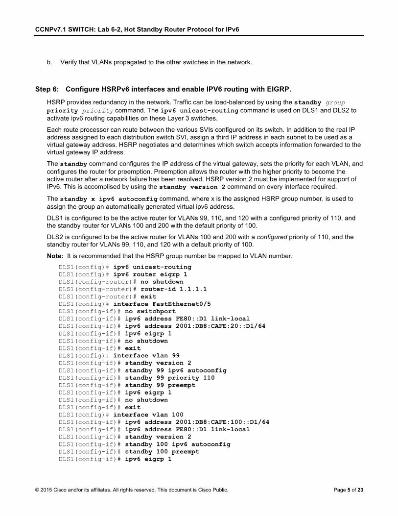
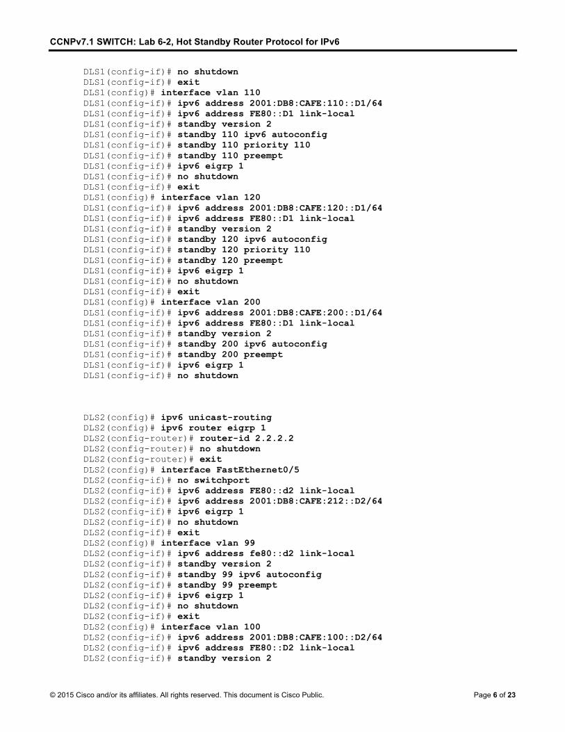
Step 6: Configure HSRPv6 interfaces and enable IPV6 routing with EIGRP.
HSRP provides redundancy in the network. Traffic can be load-balanced by using the standby group priority priority command. The ipv6 unicast-routing command is used on DLS1 and DLS2 to activate ipv6 routing capabilities on these Layer 3 switches.
Each route processor can route between the various SVIs configured on its switch. In addition to the real IP address assigned to each distribution switch SVI, assign a third IP address in each subnet to be used as a virtual gateway address. HSRP negotiates and determines which switch accepts information forwarded to the virtual gateway IP address.
The standby command configures the IP address of the virtual gateway, sets the priority for each VLAN, and configures the router for preemption. Preemption allows the router with the higher priority to become the active router after a network failure has been resolved. HSRP version 2 must be implemented for support of IPv6. This is accomplised by using the standby version 2 command on every interface required.
The standby x ipv6 autoconfig command, where x is the assigned HSRP group number, is used to assign the group an automatically generated virtual ipv6 address.
DLS1 is configured to be the active router for VLANs 99, 110, and 120 with a configured priority of 110, and the standby router for VLANs 100 and 200 with the default priority of 100.
DLS2 is configured to be the active router for VLANs 100 and 200 with a configured priority of 110, and the standby router for VLANs 99, 110, and 120 with a default priority of 100.
Note: It is recommended that the HSRP group number be mapped to VLAN number.
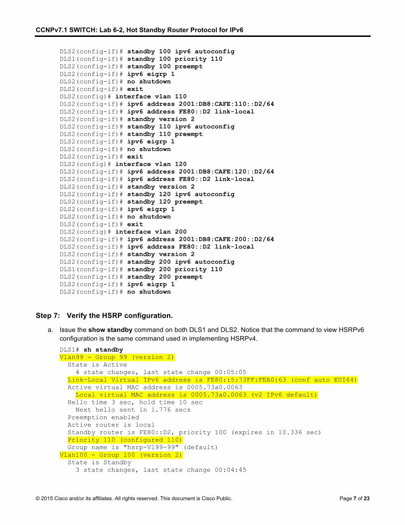
a. Issue the show standby command on both DLS1 and DLS2. Notice that the command to view HSRPv6 configuration is the same command used in implementing HSRPv4. DLS1# sh standby Vlan99 - Group 99 (version 2) State is Active 4 state changes, last state change 00:05:05 Link-Local Virtual IPv6 address is FE80::5:73FF:FEA0:63 (conf auto EUI64) Active virtual MAC address is 0005.73a0.0063 Local virtual MAC address is 0005.73a0.0063 (v2 IPv6 default) Hello time 3 sec, hold time 10 sec Next hello sent in 1.776 secs Preemption enabled Active router is local Standby router is FE80::D2, priority 100 (expires in 10.336 sec) Priority 110 (configured 110) Group name is "hsrp-Vl99-99" (default) Vlan100 - Group 100 (version 2) State is Standby 3 state changes, last state change 00:04:45
CCNPv7.1 SWITCH: Lab 6-2, Hot Standby Router Protocol for IPv6
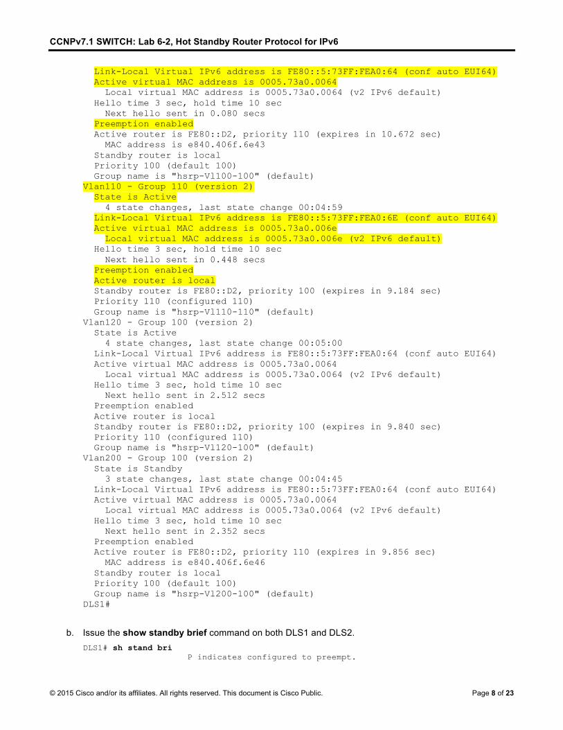
Link-Local Virtual IPv6 address is FE80::5:73FF:FEA0:64 (conf auto EUI64) Active virtual MAC address is 0005.73a0.0064 Local virtual MAC address is 0005.73a0.0064 (v2 IPv6 default) Hello time 3 sec, hold time 10 sec Next hello sent in 0.080 secs Preemption enabled Active router is FE80::D2, priority 110 (expires in 10.672 sec) MAC address is e840.406f.6e43 Standby router is local Priority 100 (default 100) Group name is "hsrp-Vl100-100" (default) Vlan110 - Group 110 (version 2) State is Active 4 state changes, last state change 00:04:59 Link-Local Virtual IPv6 address is FE80::5:73FF:FEA0:6E (conf auto EUI64) Active virtual MAC address is 0005.73a0.006e Local virtual MAC address is 0005.73a0.006e (v2 IPv6 default) Hello time 3 sec, hold time 10 sec Next hello sent in 0.448 secs Preemption enabled Active router is local Standby router is FE80::D2, priority 100 (expires in 9.184 sec) Priority 110 (configured 110) Group name is "hsrp-Vl110-110" (default) Vlan120 - Group 100 (version 2) State is Active 4 state changes, last state change 00:05:00 Link-Local Virtual IPv6 address is FE80::5:73FF:FEA0:64 (conf auto EUI64) Active virtual MAC address is 0005.73a0.0064 Local virtual MAC address is 0005.73a0.0064 (v2 IPv6 default) Hello time 3 sec, hold time 10 sec Next hello sent in 2.512 secs Preemption enabled Active router is local Standby router is FE80::D2, priority 100 (expires in 9.840 sec) Priority 110 (configured 110) Group name is "hsrp-Vl120-100" (default) Vlan200 - Group 100 (version 2) State is Standby 3 state changes, last state change 00:04:45 Link-Local Virtual IPv6 address is FE80::5:73FF:FEA0:64 (conf auto EUI64) Active virtual MAC address is 0005.73a0.0064 Local virtual MAC address is 0005.73a0.0064 (v2 IPv6 default) Hello time 3 sec, hold time 10 sec Next hello sent in 2.352 secs Preemption enabled Active router is FE80::D2, priority 110 (expires in 9.856 sec) MAC address is e840.406f.6e46 Standby router is local Priority 100 (default 100) Group name is "hsrp-Vl200-100" (default) DLS1#
b. Issue the show standby brief command on both DLS1 and DLS2. DLS1# sh stand bri P indicates configured to preempt.
CCNPv7.1 SWITCH: Lab 6-2, Hot Standby Router Protocol for IPv6
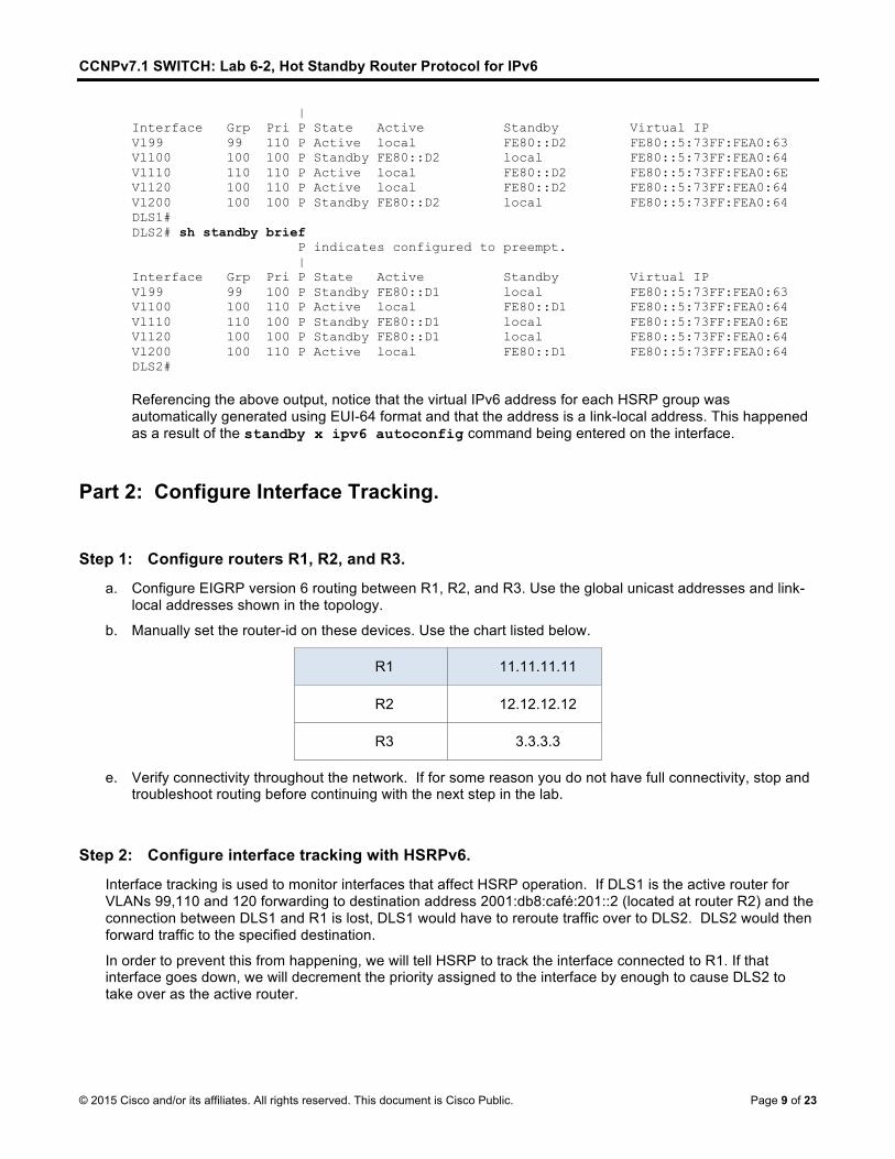
| Interface Grp Pri P State Active Standby Virtual IP Vl99 99 110 P Active local FE80::D2 FE80::5:73FF:FEA0:63 Vl100 100 100 P Standby FE80::D2 local FE80::5:73FF:FEA0:64 Vl110 110 110 P Active local FE80::D2 FE80::5:73FF:FEA0:6E Vl120 100 110 P Active local FE80::D2 FE80::5:73FF:FEA0:64 Vl200 100 100 P Standby FE80::D2 local FE80::5:73FF:FEA0:64 DLS1# DLS2# sh standby brief P indicates configured to preempt. | Interface Grp Pri P State Active Standby Virtual IP Vl99 99 100 P Standby FE80::D1 local FE80::5:73FF:FEA0:63 Vl100 100 110 P Active local FE80::D1 FE80::5:73FF:FEA0:64 Vl110 110 100 P Standby FE80::D1 local FE80::5:73FF:FEA0:6E Vl120 100 100 P Standby FE80::D1 local FE80::5:73FF:FEA0:64 Vl200 100 110 P Active local FE80::D1 FE80::5:73FF:FEA0:64 DLS2# Referencing the above output, notice that the virtual IPv6 address for each HSRP group was automatically generated using EUI-64 format and that the address is a link-local address. This happened as a result of the standby x ipv6 autoconfig command being entered on the interface.
Part 2: Configure Interface Tracking.
Step 1: Configure routers R1, R2, and R3.
a. Configure EIGRP version 6 routing between R1, R2, and R3. Use the global unicast addresses and link-local addresses shown in the topology.
b. Manually set the router-id on these devices. Use the chart listed below.
R1 11.11.11.11
R2 12.12.12.12
R3 3.3.3.3
e. Verify connectivity throughout the network. If for some reason you do not have full connectivity, stop and troubleshoot routing before continuing with the next step in the lab.
Step 2: Configure interface tracking with HSRPv6.
Interface tracking is used to monitor interfaces that affect HSRP operation. If DLS1 is the active router for VLANs 99,110 and 120 forwarding to destination address 2001:db8:café:201::2 (located at router R2) and the connection between DLS1 and R1 is lost, DLS1 would have to reroute traffic over to DLS2. DLS2 would then forward traffic to the specified destination.
In order to prevent this from happening, we will tell HSRP to track the interface connected to R1. If that interface goes down, we will decrement the priority assigned to the interface by enough to cause DLS2 to take over as the active router.
CCNPv7.1 SWITCH: Lab 6-2, Hot Standby Router Protocol for IPv6
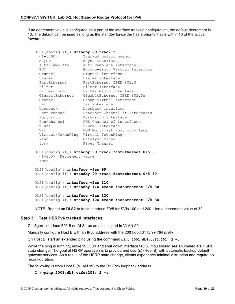
If no decrement value is configured as a part of the interface tracking configuration, the default decrement is 10. The default can be used as long as the standby forwarder has a priority that is within 10 of the active forwarder.
Configure interface F0/18 on ALS1 as an access port in VLAN 99.
Manually configure Host B with an IPv6 address with the 2001:db8:3115:99::/64 prefix
On Host B, start an extended ping using the command ping 2001:db8:café:201::2 –t
While the ping is running, move to DLS1 and shut down interface fa0/5. You should see an immediate HSRP state change. The goal of HSRP operation is to provide end user(s) (Host B) with automatic backup default-gateway services. As a result of the HSRP state change, clients experience minimal disruption and require no reconfiguration.
The following is from Host B (VLAN 99) to the R2 IPv6 loopback address.
C:\>ping 2001:db8:café:201::2 -t
CCNPv7.1 SWITCH: Lab 6-2, Hot Standby Router Protocol for IPv6
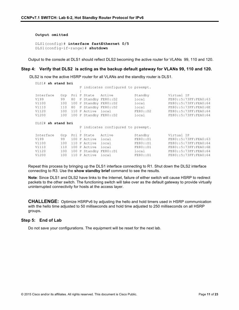
Output to the console at DLS1 should reflect DLS2 becoming the active router for VLANs 99, 110 and 120.
Step 4: Verify that DLS2 is acting as the backup default gateway for VLANs 99, 110 and 120.
DLS2 is now the active HSRP router for all VLANs and the standby router is DLS1. DLS1# sh stand bri P indicates configured to preempt. | Interface Grp Pri P State Active Standby Virtual IP Vl99 99 80 P Standby FE80::D2 local FE80::5:73FF:FEA0:63 Vl100 100 100 P Standby FE80::D2 local FE80::5:73FF:FEA0:64 Vl110 110 80 P Standby FE80::D2 local FE80::5:73FF:FEA0:6E Vl120 100 110 P Active local FE80::D2 FE80::5:73FF:FEA0:64 Vl200 100 100 P Standby FE80::D2 local FE80::5:73FF:FEA0:64 DLS2# sh stand bri P indicates configured to preempt. | Interface Grp Pri P State Active Standby Virtual IP Vl99 99 100 P Active local FE80::D1 FE80::5:73FF:FEA0:63 Vl100 100 110 P Active local FE80::D1 FE80::5:73FF:FEA0:64 Vl110 110 100 P Active local FE80::D1 FE80::5:73FF:FEA0:6E Vl120 100 100 P Standby FE80::D1 local FE80::5:73FF:FEA0:64 Vl200 100 110 P Active local FE80::D1 FE80::5:73FF:FEA0:64
Repeat this process by bringing up the DLS1 interface connecting to R1. Shut down the DLS2 interface connecting to R3. Use the show standby brief command to see the results.
Note: Since DLS1 and DLS2 have links to the Internet, failure of either switch will cause HSRP to redirect packets to the other switch. The functioning switch will take over as the default gateway to provide virtually uninterrupted connectivity for hosts at the access layer.
CHALLENGE: Optimize HSRPv6 by adjusting the hello and hold timers used in HSRP communication with the hello time adjusted to 50 milliseconds and hold time adjusted to 250 milliseconds on all HSRP groups.
Step 5: End of Lab
Do not save your configurations. The equipment will be reset for the next lab.
CCNPv7.1 SWITCH: Lab 6-2, Hot Standby Router Protocol for IPv6
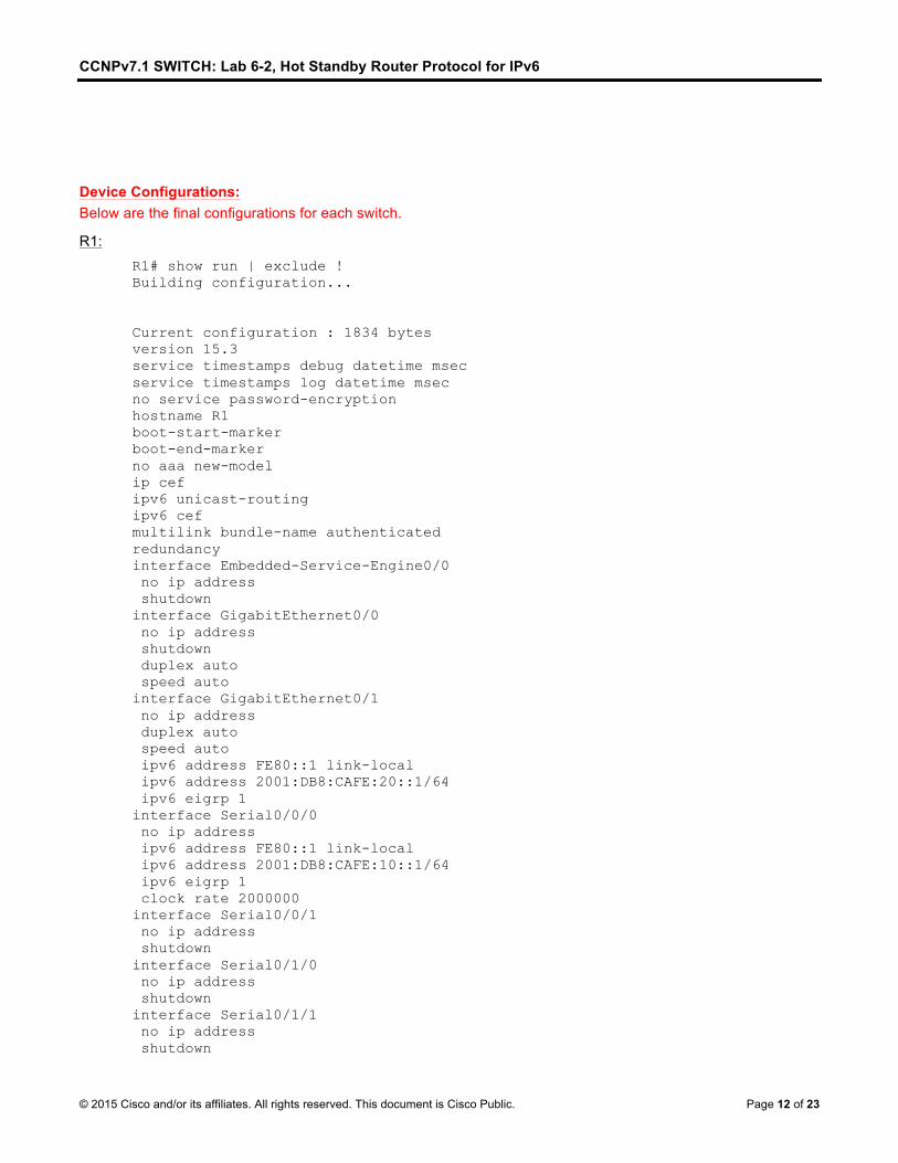
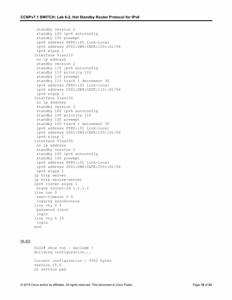
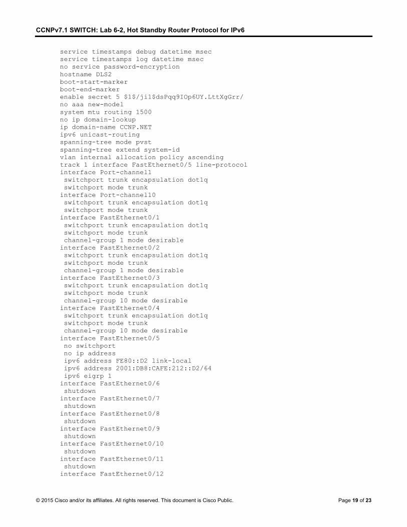
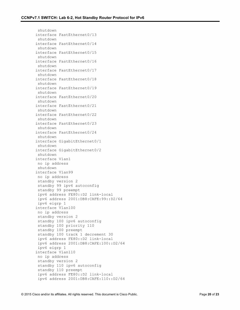
Device Configurations: Below are the final configurations for each switch.
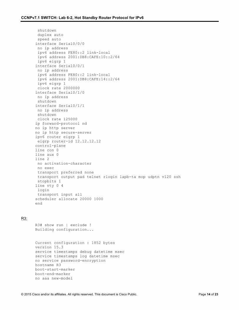
R1: R1# show run | exclude ! Building configuration... Current configuration : 1834 bytes version 15.3 service timestamps debug datetime msec service timestamps log datetime msec no service password-encryption hostname R1 boot-start-marker boot-end-marker no aaa new-model ip cef ipv6 unicast-routing ipv6 cef multilink bundle-name authenticated redundancy interface Embedded-Service-Engine0/0 no ip address shutdown interface GigabitEthernet0/0 no ip address shutdown duplex auto speed auto interface GigabitEthernet0/1 no ip address duplex auto speed auto ipv6 address FE80::1 link-local ipv6 address 2001:DB8:CAFE:20::1/64 ipv6 eigrp 1 interface Serial0/0/0 no ip address ipv6 address FE80::1 link-local ipv6 address 2001:DB8:CAFE:10::1/64 ipv6 eigrp 1 clock rate 2000000 interface Serial0/0/1 no ip address shutdown interface Serial0/1/0 no ip address shutdown interface Serial0/1/1 no ip address shutdown
CCNPv7.1 SWITCH: Lab 6-2, Hot Standby Router Protocol for IPv6
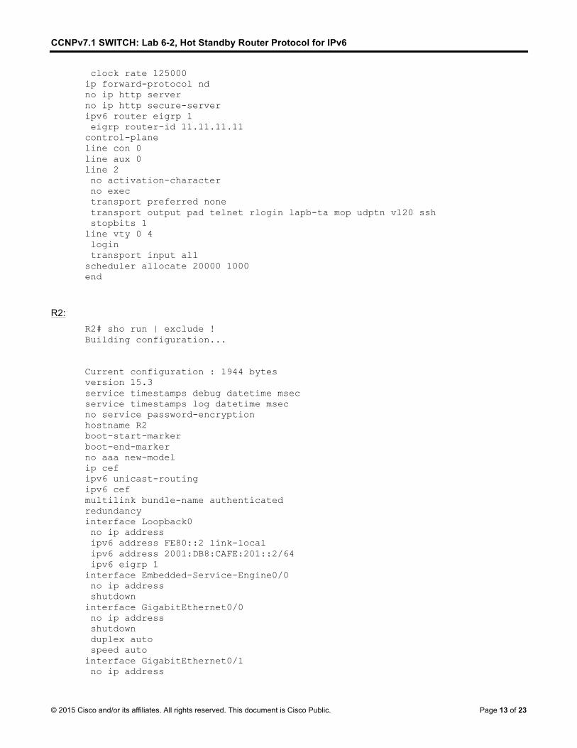
clock rate 125000 ip forward-protocol nd no ip http server no ip http secure-server ipv6 router eigrp 1 eigrp router-id 11.11.11.11 control-plane line con 0 line aux 0 line 2 no activation-character no exec transport preferred none transport output pad telnet rlogin lapb-ta mop udptn v120 ssh stopbits 1 line vty 0 4 login transport input all scheduler allocate 20000 1000 end
R2: R2# sho run | exclude ! Building configuration... Current configuration : 1944 bytes version 15.3 service timestamps debug datetime msec service timestamps log datetime msec no service password-encryption hostname R2 boot-start-marker boot-end-marker no aaa new-model ip cef ipv6 unicast-routing ipv6 cef multilink bundle-name authenticated redundancy interface Loopback0 no ip address ipv6 address FE80::2 link-local ipv6 address 2001:DB8:CAFE:201::2/64 ipv6 eigrp 1 interface Embedded-Service-Engine0/0 no ip address shutdown interface GigabitEthernet0/0 no ip address shutdown duplex auto speed auto interface GigabitEthernet0/1 no ip address
CCNPv7.1 SWITCH: Lab 6-2, Hot Standby Router Protocol for IPv6
shutdown duplex auto speed auto interface Serial0/0/0 no ip address ipv6 address FE80::2 link-local ipv6 address 2001:DB8:CAFE:10::2/64 ipv6 eigrp 1 interface Serial0/0/1 no ip address ipv6 address FE80::2 link-local ipv6 address 2001:DB8:CAFE:14::2/64 ipv6 eigrp 1 clock rate 2000000 interface Serial0/1/0 no ip address shutdown interface Serial0/1/1 no ip address shutdown clock rate 125000 ip forward-protocol nd no ip http server no ip http secure-server ipv6 router eigrp 1 eigrp router-id 12.12.12.12 control-plane line con 0 line aux 0 line 2 no activation-character no exec transport preferred none transport output pad telnet rlogin lapb-ta mop udptn v120 ssh stopbits 1 line vty 0 4 login transport input all scheduler allocate 20000 1000 end
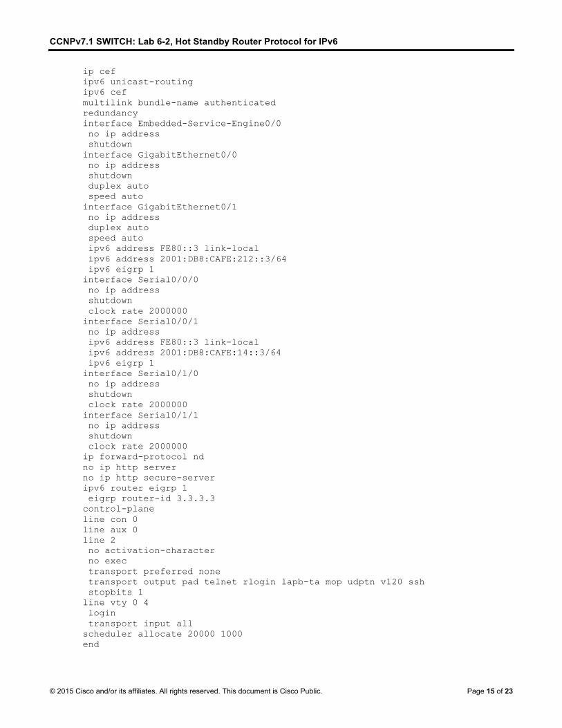
R3: R3# show run | exclude ! Building configuration... Current configuration : 1852 bytes version 15.3 service timestamps debug datetime msec service timestamps log datetime msec no service password-encryption hostname R3 boot-start-marker boot-end-marker no aaa new-model
CCNPv7.1 SWITCH: Lab 6-2, Hot Standby Router Protocol for IPv6
ip cef ipv6 unicast-routing ipv6 cef multilink bundle-name authenticated redundancy interface Embedded-Service-Engine0/0 no ip address shutdown interface GigabitEthernet0/0 no ip address shutdown duplex auto speed auto interface GigabitEthernet0/1 no ip address duplex auto speed auto ipv6 address FE80::3 link-local ipv6 address 2001:DB8:CAFE:212::3/64 ipv6 eigrp 1 interface Serial0/0/0 no ip address shutdown clock rate 2000000 interface Serial0/0/1 no ip address ipv6 address FE80::3 link-local ipv6 address 2001:DB8:CAFE:14::3/64 ipv6 eigrp 1 interface Serial0/1/0 no ip address shutdown clock rate 2000000 interface Serial0/1/1 no ip address shutdown clock rate 2000000 ip forward-protocol nd no ip http server no ip http secure-server ipv6 router eigrp 1 eigrp router-id 3.3.3.3 control-plane line con 0 line aux 0 line 2 no activation-character no exec transport preferred none transport output pad telnet rlogin lapb-ta mop udptn v120 ssh stopbits 1 line vty 0 4 login transport input all scheduler allocate 20000 1000 end
CCNPv7.1 SWITCH: Lab 6-2, Hot Standby Router Protocol for IPv6
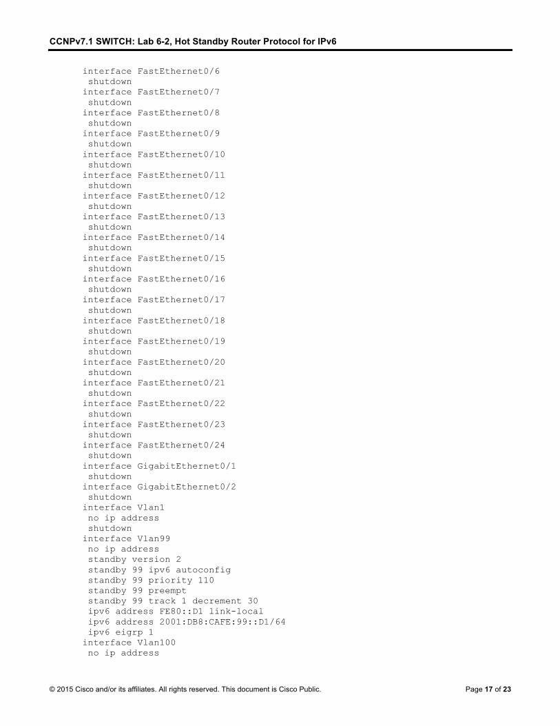
ipv6 eigrp 1 interface Vlan120 no ip address standby version 2 standby 100 ipv6 autoconfig standby 100 preempt ipv6 address FE80::D2 link-local ipv6 address 2001:DB8:CAFE:120::D2/64 ipv6 eigrp 1 interface Vlan200 no ip address standby version 2 standby 100 ipv6 autoconfig standby 100 priority 110 standby 100 preempt standby 200 track 1 decrement 30 ipv6 address FE80::D2 link-local ipv6 address 2001:DB8:CAFE:200::D2/64 ipv6 eigrp 1 ip http server ip http secure-server ipv6 router eigrp 1 eigrp router-id 2.2.2.2 line con 0 exec-timeout 0 0 logging synchronous line vty 0 4 password cisco login line vty 5 15 login end
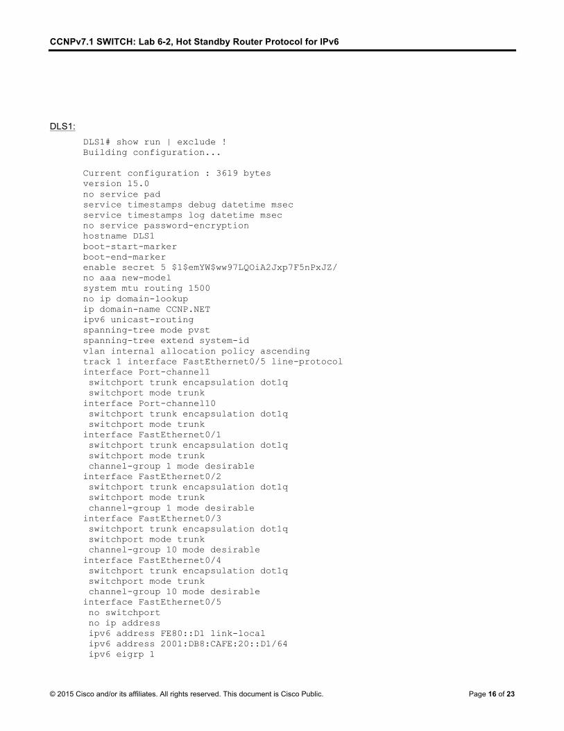
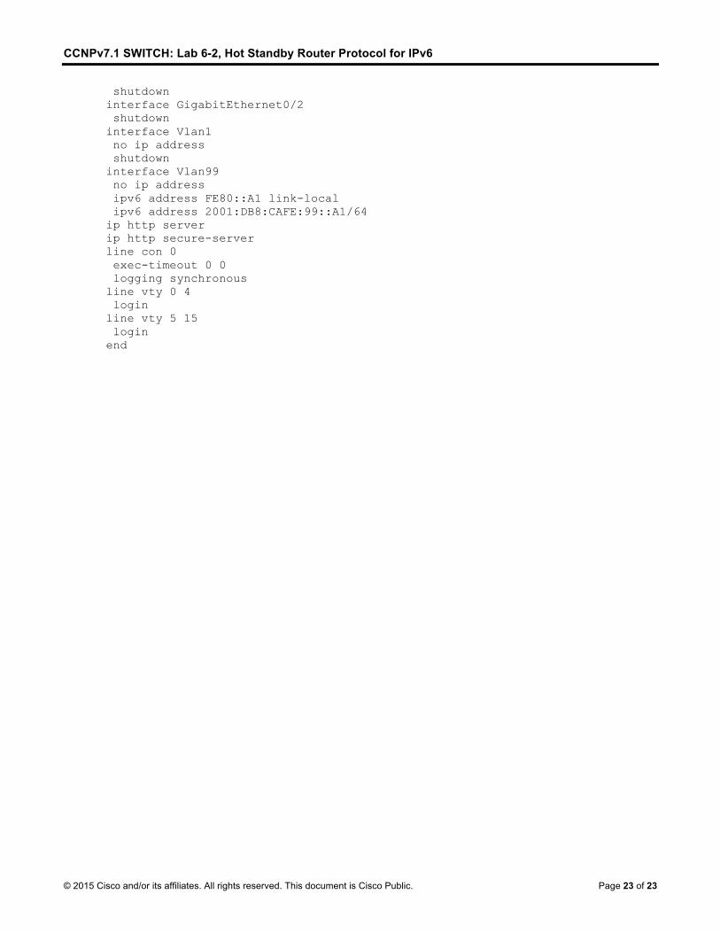
ALS1: ALS1# show run | exclude ! Building configuration... Current configuration : 2112 bytes version 15.0 no service pad service timestamps debug datetime msec service timestamps log datetime msec no service password-encryption hostname ALS1 boot-start-marker boot-end-marker no aaa new-model system mtu routing 1500 no ip domain-lookup ip domain-name CCNP.NET spanning-tree mode pvst spanning-tree extend system-id vlan internal allocation policy ascending interface Port-channel1 switchport mode trunk
CCNPv7.1 SWITCH: Lab 6-2, Hot Standby Router Protocol for IPv6
shutdown interface GigabitEthernet0/2 shutdown interface Vlan1 no ip address shutdown interface Vlan99 no ip address ipv6 address FE80::A1 link-local ipv6 address 2001:DB8:CAFE:99::A1/64 ip http server ip http secure-server line con 0 exec-timeout 0 0 logging synchronous line vty 0 4 login line vty 5 15 login end