CHAPTER 6 RESOURCE AND ENERGY CONSERVATION 6-1 Chapter 6: Resource and Energy Conservation CHAPTER CONTENTS 6.1 INK AND PRESS-SIDE SOLVENT AND ADDITIVE CONSUMPTION .................... 6-3 Methodology ............................................................. 6-3 Limitations and Uncertainties ................................................ 6-5 Ink and Press-side Solvent and Additive Consumption Estimates ..................... 6-6 6.2 ENERGY CONSUMPTION .................................................... 6-10 Methodology ............................................................ 6-10 Limitations and Uncertainties ............................................... 6-16 Energy Consumption Estimates ............................................. 6-17 6.3 ENVIRONMENTAL IMPACTS OF ENERGY REQUIREMENTS ........................ 6-23 Emissions from Energy Production ........................................... 6-24 Environmental Impacts of Energy Production ................................... 6-26 Limitations and Uncertainties ............................................... 6-26 6.4 CLEAN-UP AND WASTE DISPOSAL PROCEDURES .............................. 6-29 Press Clean-Up and Waste Reduction in the CTSA Performance Demonstrations ....... 6-30 REFERENCES ................................................................ 6-32 CHAPTER OVERVIEW This chapter discusses resource and energy use in flexographic printing and identifies opportunities for conservation. By minimizing resource and energy use, companies can improve the environment as well as their bottom line. Data presented in this chapter are based on information collected during the on-site performance demonstration runs and information from equipment vendors. Ink and energy consumption data presented in this chapter are used in the cost analysis (Chapter 5) to calculate ink and energy costs. Ink consumption data are also used to estimate environmental releases for the risk characterization (Chapter 3). INK AND PRESS-SIDE SOLVENT AND ADDITIVE CONSUMPTION: Section 6.1 presents the comparative ink and press-side solvent and additive consumption rates for solvent-based, water-based, and UV-cured ink systems. This analysis is based on the weights of inks, solvents, and additives, and on the substrate usage recorded by an on-site observer from Western Michigan University (WMU) at each demonstration site. ENERGY CONSUMPTION: Section 6.2 discusses the energy requirements of the drying systems, corona treaters, and pollution control equipment (catalytic oxidizers) typically used with the different ink systems. Electrical power and/or gas consumption data were collected by WMU and supplemented by energy estimates from equipment vendors. Due to the variability among equipment and operating procedures at
This chapter discusses resource and energy use in flexographic printing and identifies opportunities forconservation. By minimizing resource and energy use, companies can improve the environment as well astheir bottom line. Data presented in this chapter are based on information collected during the on-siteperformance demonstration runs and information from equipment vendors. Ink and energy consumptiondata presented in this chapter are used in the cost analysis (Chapter 5) to calculate ink and energy costs.Ink consumption data are also used to estimate environmental releases for the risk characterization (Chapter3). INK AND PRESS-SIDE SOLVENT AND ADDITIVE CONSUMPTION: Section 6.1 presents the comparativeink and press-side solvent and additive consumption rates for solvent-based, water-based, and UV-curedink systems. This analysis is based on the weights of inks, solvents, and additives, and on the substrateusage recorded by an on-site observer from Western Michigan University (WMU) at each demonstration site.
ENERGY CONSUMPTION: Section 6.2 discusses the energy requirements of the drying systems, coronatreaters, and pollution control equipment (catalytic oxidizers) typically used with the different ink systems.Electrical power and/or gas consumption data were collected by WMU and supplemented by energyestimates from equipment vendors. Due to the variability among equipment and operating procedures at
CHAPTER 6 RESOURCE AND ENERGY CONSERVATION
6-2
the different test sites, equipment vendor estimates, rather than site-specific data, are used in the costanalysis to calculate energy costs.
ENVIRONMENTAL IMPACTS OF ENERGY REQUIREMENTS: Section 6.3 presents the environmentalimpacts of electricity generation and natural gas combustion, using software that quantifies emissions. Theresults are calculated for each ink system based on the rate of energy consumption at the methodology pressspeed (500 feet per minute) and the average press speeds observed at the performance demonstrations.
CLEAN-UP AND WASTE DISPOSAL PROCEDURES: Section 6.4 discusses the clean-up procedures usedat the performance demonstration sites, as well as some of the broader life-cycle issues associated withenergy and natural resource use.
HIGHLIGHTS OF RESULTS
• UV-cured inks had the lowest ink consumption rates. In addition, UV inks required almost nopress-side additions. Solvent-based inks had the highest consumption rates for ink and materialsadded at press-side.
• Water-based inks consumed the least amount of energy (assuming pollution control equipmentis not needed). At a press speed of 500 feet per minute, UV-cured inks were the next lowestconsumer, but at the press speeds observed during the performance demonstration, solvent-basedinks were the second-lowest energy consumer per unit of image.
• For solvent- and water-based inks, air recirculation in dryer units can significantly reduceenergy requirements by increasing the temperature of the incoming air.
• The environmental impacts due to energy production were lowest for water-based inks. Thisink system consumed the least amount of energy, and much of the energy it did use was derivedfrom natural gas. Based on a national average of energy emissions by source, the CTSA found thatnatural gas released less emissions per unit of energy than electricity. Depending on thegeographical location of a flexographic printing facility (and thus the specific electricity source),emissions could be very different.
• Most solvent-based and some water-based ink wastes are classified as hazardous waste. Non-hazardous waste (e.g., waste substrate and some cleaning solutions) can be recycled or reused.
CAVEATS
• Ink consumption was calculated during the performance demonstrations by recording the amountof ink added to the press and subtracting the amount removed during cleanup. Several site-specificfactors could have affected the calculated ink consumption figures: type of cleaning equipment,anilox roll size, and the level of surface tension of the substrate.
• The energy consumption section only considers equipment that would differ among the ink systems.Therefore, drying/curing equipment is included, but substrate winding equipment and ink pumps arenot.
• Except for corona treaters, information was not available about the difference in energyrequirements when equipment is run at different press speeds. UV lamps also will have differentenergy demands at different energy speeds, but it is assumed in this analysis that their energyconsumption is constant. Therefore, the energy consumption of UV lamps may be overestimatedat lower press speeds.
• The clean-up and waste disposal procedures section presents the methods observed at theperformance demonstration sites. These procedures were developed independently by theindividual sites, and do not represent recommended practices by EPA.
CHAPTER 6 RESOURCE AND ENERGY CONSERVATION
6-3
6.1 INK AND PRESS-SIDE SOLVENT AND ADDITIVE CONSUMPTION
By reducing resource consumption, businesses can increase process efficiency, decreaseoperating costs, and decrease demand for natural resources. Ink is one of the main resourcesconsumed by the flexographic printing process. The amount of ink required to print an imagenot only affects printing costs, but also influences the potential risk to workers and theenvironment from exposure to ink constituents. This section of the CTSA presents averageconsumption of inks and press-side additions from the performance demonstrations. The dataare in units of pounds of ink consumed per 6,000 images and per 6,000 ft2 of image, asprinters commonly use these terms in estimating and comparing costs.
Methodology
The amounts of ink, press-side materials, and substrate consumed during the performancedemonstrations are shown in Appendix 6-A.
The on-site observer weighed the pre-mixed ink components (extender, water, solvent, etc.)that were put in the ink sump at the beginning of makeready and whenever ink componentswere added to the sump. During clean-up, the observer weighed the ink remaining in thesump, the ink scraped or wiped out of the press, the cleaning solution (water, detergent, orsolvent) added to the press, and the ink and cleaning solution removed from the press. Thetotal ink consumed during makeready and the demonstration run for each color was calculatedfrom the following equation.
Itotal = Ipre + 3Iadd-mk + 3Iadd-pr - Ir - Is + Cin - Cout
where
Itotal = total amount of ink plus press-side solvents and additives consumed (printedor evaporated) during makeready and the demonstration run
Ipre = amount of pre-mixed ink put in the ink sump at the beginning of makeready3Iadd-mk = the sum of additional ink components put in the ink sump during makeready3Iadd-pr = the sum of the ink components added to the system during the press runIr = amount of ink remaining in the sump at the end of the runIs = amount of ink scraped or wiped out of the press at the end of the runCin = amount of cleaning solution added to the press during clean-upCout = amount of cleaning solution and ink mixture removed from the press during
clean-up
Ink ConsumptionInk consumption was calculated for each demonstration site using the following information:
C total amount of ink consumed during makeready and the press run (Itotal)C amount of substrate printed (S)C total area of the image (16 by 20 inches with a 16-inch repeat)
Substrate consumption was recorded from the press meter at the beginning of makeready, atthe end of makeready, and at the end of the press run for each substrate. The consumptionnumbers are listed in Appendix 6-A.
CHAPTER 6 RESOURCE AND ENERGY CONSERVATION
6-4
Sample calculations for white, water-based ink at Site 1 follow, to help readers understandthe methodology and to allow reproducibility of results. The complete data are provided inAppendix 6-A.
Total white ink consumed (Itotal) = 56.4 pounds (lbs)Total substrate consumed including makeready (S) = 62,892 linear feet (ft)Total area of image = 2.22 square feet (ft2)Repeat length of image = 1.33 ft
Number of images (N) = S / 1.33 feet per image= 62,892 feet / 1.33 feet per image= 47,200 images
Ink per 6,000 images = (Itotal/N) × 6,000 images= (56.4 lbs/47,200 images) × 6,000 images= 7.17 lbs per 6,000 images
Ink per 6,000 ft2 of image = (Itotal/N) × 6,000 ft2 of image / Area of image= (56.4 lbs/47,200 images) × 6,000 ft2 / 2.22 ft2 per image= 3.23 lbs per 6,000 ft2 of image
White ink was not printed on the PE/EVA substrate. Thus, PE/EVA substrate is excludedfrom ink consumption calculations for white ink.
Table 6.1 presents the percent area of coverage for each ink. White dominates the inkcoverage of the image (60.8%), blue and green (line colors) account for 24.1% coverage, andcyan and magenta (process colors) account for 5.2% coverage.
aThe total percent coverage does not equal 100% because of overlapping colors and unprinted area.
Facilities running more than one substrate did not clean the press between substrates. Thus,only total weights, not the weight of ink applied to each substrate, are available. For thepurposes of this analysis, it is assumed that the weight of ink consumed per unit area is nota function of the film type.
Press-side Solvent and Additive ConsumptionDuring the course of a print run, printers may add solvent or water to correct the viscosity ofthe ink, or other components, such as extenders or cross-linkers, to improve the performanceof the ink. Solvent and additive weights were calculated assuming the weight of eachcomponent consumed is directly proportional to the component weight added to the system.
CHAPTER 6 RESOURCE AND ENERGY CONSERVATION
6-5
The solvent and additive consumption rates were then calculated in a manner similar to theink consumption rates.
The method for calculating ink weights assumes equal volatilization rates for each component.It does not account for solvent emissions from the ink sump or ink pan. Because solvents areexpected to volatilize at a more rapid rate than other components, this method slightlyunderestimates solvent consumption rates and slightly overestimates rates for the othercomponents. Sample calculations for solvent and additive weights using solvent-based, blueink data from Site 5 follow, with numbers taken from Table 6-A.12 in Appendix 6-A:
Weight of blue ink added to system (Iadded) = 20.90 lbsWeight of solvent added to the blue ink (Sadded) = 4.81 lbsTotal ink used (IT) = 18.16 lbs
Total components added (T) = Iadded + Sadded
= 20.90 lbs + 4.81 lbs= 25.71 lbs
Ratio of Iadded to T (RI) = 20.90 lbs / 25.71 lbs= 0.81
Ratio of Sadded to T (RS) = 4.81 lbs / 25.71 lbs= 0.19
Weight of ink consumed = IT × RI
= 18.16 lbs × 0.81= 14.8 lbs
Weight of solvent consumed = IT × RS
= 18.16 lbs × 0.19= 3.4 lbs
Limitations and Uncertainties
The limitations of and uncertainties in the data are related to the limited number ofdemonstration sites, variability among the equipment and operating procedures at the testsites, and uncertainties in the measured ink component weights. Each of these are discussedbelow.
Limitations Due to the Number of Demonstration SitesInk consumption data were collected during twelve performance demonstrations at tenflexographic printing facilities across the United States and one press manufacturer’s pilot linein Germany. As such, the data represent a “snapshot” of how the inks performed at the timeof the performance demonstrations (November 1996 — March 1997) under actual operatingconditions at a limited number of facilities. Because no two printing plants are identical, thesample may not be representative of all flexographic printing plants (although there is nospecific reason to believe they are not representative).
Variability among Equipment and Operating ProceduresSeveral operating parameters were specified in the performance demonstration methodology(see Appendix 6-B) in an attempt to ensure consistent conditions across demonstration sites.
CHAPTER 6 RESOURCE AND ENERGY CONSERVATION
6-6
These included target specifications for anilox rolls (screen count and anilox volume) whichdirectly affect the amount of ink applied to print an image.
The specified target ranges for the anilox rolls were not always met. Because of theproduction needs of the volunteer facilities, changing anilox rolls or acquiring new anilox rollsto meet the specified targets was impractical. Table 6.2 lists the target anilox specificationsand the average configurations by ink type for the anilox rolls actually used at thedemonstration sites. The Site Profiles section of the Performance chapter (Chapter 4) lists theparticular anilox configurations used at each of the test sites. Facilities using anilox volumesand screen counts greater than the specifications would be expected to consume more ink toprint the test image. Similarly, facilities using anilox volumes and screen counts less than thespecifications would be expected to consume less ink to print the test image. Also, thesespecifications do not address the fact that the anilox roll volume would differ depending onthe color printed; for example, the volumes for light colors would be larger than those for darkcolors.
Table 6.2 Average Anilox Configurations and Target Anilox Specifications
InkScreen count (lpi)a Volume (BCM)b
Line(color)
Line(white)
Process Line(color)
Line(white)
Process
TargetSpecifications
440 150 600 to700
4 to 6 6 to 8 1.5
Solvent-based 350 260 650 5.5 6.8 2.1
Water-based 290 300 580 6.3 5.9 3.0
UV-cured 480 250 610 4.9 7.3 3.3alines per inchbbillion cubic microns per square inch
Uncertainties in Ink Component WeightsAs discussed previously, the on-site observer collected information on the amounts of ink,solvents, additives, and cleaning solution added to or removed from the system duringmakeready, the press run, and clean-up. In some cases, however, site operating procedures,such as the type of cleaning system being used, prevented measurement of some of theseparameters. In these cases, the weights were estimated based on other site data.
Ink and Press-side Solvent and Additive Consumption Estimates
Tables 6.3 and 6.4 present the average ink and and press-side solvent and additiveconsumption rates for the performance demonstration sites by ink type, substrate, and color.Site-specific consumption rates can be found in Tables 6-A.3 and 6-A.4 in Appendix 6-A.
In general, the UV-cured ink formulations used substantially less ink than the solvent-basedor water-based formulations. On LDPE, the UV-cured ink systems used 57% less ink thanthe solvent-based ink systems and 28% less than the water-based ink systems. On PE/EVA,the UV-cured ink systems used 82% less ink than the solvent-based ink systems and 56% lessthan the water-based ink systems. These results are consistent with the general expectation
CHAPTER 6 RESOURCE AND ENERGY CONSERVATION
6-7
that less UV-cured ink is needed because nearly all of the ingredients are incorporated into thedried coating, unlike with solvent- and water-based inks.
Components added to the water-based ink formulations included water, extender, solvent,ammonia, cross-linker, slow reducer, and defoamer. Components added to the solvent-basedformulations were primarily solvents, but one company also added extender to the ink,whereas another added acetate. Water-based ink solvents and additives tended to comprisea smaller percentage of the overall total weight than did solvent-based ink solvents andadditives. In the solvent-based systems, these additions accounted for about 25% of totalconsumption. No additives were used at the UV-cured ink demonstration sites, except for alow-viscosity monomer added to the green ink at Site 11.
CH
APTE
R 6
R
ESO
UR
CE
AND
EN
ERG
Y C
ON
SER
VATI
ON
6-8
Tabl
e 6.
3 A
vera
ge In
k an
d Pr
ess-
side
Sol
vent
and
Add
itive
Con
sum
ptio
n R
ates
for P
erfo
rman
ce D
emon
stra
tions
(Pou
nds
per 6
,000
Imag
es)
Ink
Solv
ents
and
Add
itive
sSu
b-to
tal:
Ink
Sub-
tota
l:So
lven
ts a
ndAd
ditiv
esTo
tal
Blu
eG
reen
Whi
tea
Cya
nM
agen
taEx
tend
erSo
lven
tAd
ditiv
es
Solv
ent-b
ased
ink
LDPE
2.34
2.63
7.36
2.91
2.77
0.00
5.61
0.00
18.0
15.
6123
.62
PE/E
VA2.
342.
630.
002.
912.
770.
003.
780.
0010
.65
3.78
14.4
3
OPP
1.36
1.55
7.86
1.37
1.25
0.16
4.44
0.78
13.3
95.
3818
.77
Wat
er-b
ased
ink
LDPE
1.30
1.45
6.53
0.75
0.75
0.16
0.26
0.64
10.7
81.
0611
.84
PE/E
VA1.
301.
450.
000.
750.
750.
000.
060.
374.
250.
434.
68
OPP
1.30
1.09
6.79
0.59
0.60
0.19
0.17
0.08
10.3
70.
4410
.81
UV-
cure
d in
k
LDPE
0.94
0.73
5.18
0.37
0.48
0.00
0.00
0.01
7.71
0.01
7.72
PE/E
VA0.
680.
440.
000.
340.
430.
000.
000.
001.
890.
001.
89
OPP
n/ab
n/a
n/a
n/a
n/a
n/a
n/a
n/a
n/a
n/a
n/a
a Whi
te in
k w
as n
ot p
rinte
d on
PE/
EVA.
b n/a
= no
t app
licab
le; t
here
wer
e no
suc
cess
ful r
uns
of U
V-cu
red
ink
on O
PP in
the
perfo
rman
ce d
emon
stra
tions
.
CH
APTE
R 6
R
ESO
UR
CE
AND
EN
ERG
Y C
ON
SER
VATI
ON
6-9
Tabl
e 6.
4 A
vera
ge In
k an
d Pr
ess-
side
Sol
vent
and
Add
itive
Con
sum
ptio
n R
ates
for P
erfo
rman
ce D
emon
stra
tions
(Pou
nds
per 6
,000
Squ
are
Feet
of I
mag
e)
Ink
Solv
ents
and
Add
itive
sSu
b-to
tal:
Ink
Sub-
tota
l:So
lven
ts a
ndAd
ditiv
esTo
tal
Blu
eG
reen
Whi
tea
Cya
nM
agen
taEx
tend
erSo
lven
tAd
ditiv
es
Solv
ent-b
ased
ink
LDPE
1.05
1.18
3.31
1.31
1.27
0.00
2.52
0.00
8.12
2.52
10.6
4
PE/E
VA1.
051.
180.
001.
311.
270.
001.
700.
004.
811.
706.
51
OPP
0.61
0.70
3.54
0.62
0.56
0.08
2.00
0.35
6.03
2.43
8.46
Wat
er-b
ased
ink
LDPE
0.58
0.65
2.94
0.34
0.34
0.07
0.12
0.28
4.85
0.47
5.32
PE/E
VA0.
580.
650.
000.
340.
340.
000.
030.
181.
910.
212.
12
OPP
0.58
0.49
3.05
0.40
0.27
0.09
0.08
0.04
4.79
0.21
5.00
UV-
cure
d in
k
LDPE
0.42
0.33
2.33
0.16
0.22
0.00
0.00
<0.0
13.
460.
003.
46
PE/E
VA0.
310.
200.
000.
150.
200.
000.
000.
000.
860.
000.
86
OPP
n/ab
n/a
n/a
n/a
n/a
n/a
n/a
n/a
n/a
n/a
n/a
a Whi
te in
k w
as n
ot p
rinte
d on
PE/
EVA.
b n/a
= no
t app
licab
le; t
here
wer
e no
suc
cess
ful r
uns
of U
V-cu
red
ink
on O
PP in
the
perfo
rman
ce d
emon
stra
tions
.
CHAPTER 6 RESOURCE AND ENERGY CONSERVATION
6-10
6.2 ENERGY CONSUMPTION
Energy conservation is an important goal for flexographic printers who strive to cut costs andseek to improve environmental performance. This section of the CTSA discusses theelectricity and natural gas consumption rates of the flexographic printing equipment listed inTable 6.5, including background information and assumptions. Energy consumption rates areused in the cost analysis (Chapter 5) to calculate energy costs. They are also used in Section6.3 to evaluate the life-cycle environmental impacts of energy consumption.
Table 6.5 Equipment Evaluated in the Energy Analysis
Equipment FunctionInk system
Solvent-based
Water-based
UV-cured
Hot air dryingsystem
Dries the ink between stations and in theoverhead tunnel (main) dryer.
U U
Catalyticoxidizera
Converts VOCs to carbon dioxide andwater.
U
Corona treater Increases the surface tension of thesubstrate to improve ink adhesion.
U U
UV curingsystem
Cures UV-cured ink applied to substrate. U
aIn some states, oxidizers may be required for water-based inks with high VOC content.
Energy estimates were to be prepared from the individual site data for each of the performancedemonstration sites, similar to the site-specific ink consumption estimates presented in Section6.1. However, limited or no energy data were available for one or more pieces of equipmentat several of the sites, particularly for catalytic oxidizers used at solvent-based sites. Inaddition, press size, age, and condition of presses varied significantly across sites, as didequipment operating conditions, such as dryer temperature. For these reasons, equipmentvendor estimates, rather than site-specific data, are used in the cost analysis to calculateenergy costs.
Methodology
This section presents the methodology used to estimate energy requirements and providesbackground information and key assumptions on the types of equipment evaluated: hot airdrying systems, catalytic oxidizers, corona treaters, and UV curing systems.
Energy ConsumptionEquipment vendors estimated equipment energy requirements in kilowatts (kW) for electricalpower and British thermal units (Btu) per hour for natural gas. This information was thenconverted into energy consumption rates for each ink type in Btus per 6,000 images and per6,000 ft2 of printed substrate. Table 6.6 lists the press, substrate, and image characteristicsused in the energy estimates. These characteristics are consistent with assumptions used inthe cost analysis and with the substrates and image printed during the on-site performancedemonstrations. Where applicable, two sets of estimates were made: one using the project
CHAPTER 6 RESOURCE AND ENERGY CONSERVATION
6-11
methodology press speed of 500 feet per minute (fpm) for all three ink types, and one usingthe average press speed achieved for each ink type at the performance demonstration facilities.Additional assumptions for each type of equipment and energy rate calculations are listed inthe sections below.
Table 6.6 Press, Substrate, and Image Information for Estimating Energy Use
Parameter Description CommentsPress 48-inch, 6-color, CI press; new, average
qualityPress costs are presented inChapter 5.
Pressspeed
Solvent-based ink: 500 fpm and 453 fpmWater-based ink: 500 fpm and 394 fpmUV-cured ink: 500 fpm and 340 fpm
Two scenarios for each inksystem are used in thecorona treatment energyestimates.
Substrates LDPE, PE/EVA, OPP
Web width 20 inches A second case assuming a40-inch web was used inoxidizer and corona treaterenergy estimates.
Image size 16 in x 20 in (2.22 ft2)
Sample calculations based on the average press speed at water-based sites follow. Estimateswere provided by equipment vendors.
Hot Air Drying SystemsMost solvent-based and water-based presses are equipped with between-color (interstation)dryers (BCDs) and an overhead (main) dryer. Supply and exhaust blowers are used toprovide air flow through the dryers and maintain negative pressure within the dryer. Thesupply blowers draw air into the drying system to be heated by the burners. Most printersdraw the dryer make-up air from the ambient environment outside the plant.1 Exhaust blowersare used to draw the heated air though the dryers to the exhaust outlet.
The BCDs are positioned after each print station. They dry each color as it is applied to theweb to prevent pick-up or tracking when the next color is applied. The overhead dryerconsists of a tunnel located above the print stations, through which the web passes to furtherdry the ink before the web is rewound.
The energy consumed by hot air drying systems includes electrical power for the supply andexhaust blowers and natural gas for the drying oven. Typically, the gas energy required toheat the process air is greater than the energy needed to dry the ink.2
Kidder, Inc., a press manufacturer, provided energy estimates for hot air drying systems basedon the press, substrate, and image details listed in Table 6.6, the average ink consumptionrates listed in Table 6.3, and the hot air drying system assumptions listed in Table 6.7. Dryerenergy estimates for both solvent- and water-based inks are based on the same air flow ratesbut different dryer temperatures. New presses are now designed to work with either water-based or solvent-based inks. Usually, a press operator will reduce the amount of heat insteadof the air flow when using solvent-based inks.3 Air flow rates are given in units of cubic feetper minute (cfm).
CHAPTER 6 RESOURCE AND ENERGY CONSERVATION
6-13
Table 6.7 Hot Air Drying System Assumptions
Parameter Assumption CommentsBCD air flow rate 2800 cfm Four dryer boxes at 700 cfm/box, based on
average BCD flow rate of 15 cfm/inch ofwidth/dryer boxa
Main dryer air flow rate 3000 cfm Typical value for 48-inch pressa
Dryer temperature(solvent-based Inks)
150oF Typical temperature for Project substratesa
Dryer temperature(water-based inks)
200oF Typical temperature for Project substratesa
Make-up (outdoor) airtemperature
0oF, 50oF, 70oF Three scenarios
Percent recirculation ofdryer air
0%, 50% Two scenarios
cfm = cubic feet per minute.a Reference 4.
The assumed dryer temperature for water-based inks is higher than the maximum temperatureto which some film substrates can be subjected without potentially damaging the film.However, in practice, the film temperature would be less than the dryer temperature due toimpression cylinder cooling and evaporative cooling.5
The hot air drying system energy estimates were prepared for six different operating scenarios,assuming three different outside air temperatures for the make-up air and two dryer airrecirculation scenarios (no recirculation and 50% recirculation). All six scenarios wereanalyzed to illustrate the influence make-up air temperature and air recirculation on dryercosts. The different air temperatures represent the range of air temperatures that might beencountered in different seasons. If make-up air is taken from the outdoor environment (asis typically done), dryer costs will be significantly higher in winter than in summer. The 50oFtemperature was used in the cost analysis to represent an annual average. Most new pressesare designed to recirculate dryer air, either to save on dryer air heating costs or to reduce theair flow to the pollution control device.6 However, many older presses do not have dryer airrecirculation, and retrofitting may be ineffective with smaller, low air flow presses. Arecirculation rate of 50% was used in the cost analysis since this is more representative of anew press, the subject of the cost analysis.
Catalytic OxidizersA catalytic oxidizer is a type of add-on emissions control equipment used to convert VOCemissions to carbon dioxide and water by high temperature oxidation. Catalytic incineratorsemploy a catalyst bed to facilitate the overall combustion reaction by increasing the reactionrate. This enables conversion at lower reaction temperatures than in thermal oxidizers.Oxidizers are used primarily with solvent-based inks, but may be required with water-basedinks in some states.
A basic catalytic oxidizer assembly consists of a heat exchanger, a burner, and a catalyst.First, the dryer exhaust stream is preheated by heat exchange with the oxidizer effluent and,where necessary, further heated to the desired catalyst inlet temperature by a natural gas-firedburner. The heated stream then passes through the catalyst where VOCs are converted to
CHAPTER 6 RESOURCE AND ENERGY CONSERVATION
a Technology developments are allowing for decreased catalyst inlet temperatures. A published estimatenotes that a typical catalyst inlet temperature is 550-700°F. Another industry estimate notes that withsolvent loading, the typical temperature can rise to 650°F. However, some new oxidizers are capable ofoperating at 500°F.
6-14
carbon dioxide and water. The combustion reaction between oxygen and gaseous pollutantsin the waste stream occurs at the catalyst surface. The oxidizer effluent is then recirculatedback to the heat exchanger and may also be recirculated to the dryer to save drying fuel.
Two oxidizer suppliers, Anguil Environmental Systems, Inc. and MEGTEC Systems[formerly Wolverine (Massachusetts) Corporation], provided energy estimates based on thepress, substrate, and image details listed in Table 6.6 and the additional oxidizer assumptionspresented in Table 6.8.7 As with the other equipment, the oxidizer energy estimates representenergy requirements for a particular set of circumstances (e.g., solvent loading, dryer exhausttemperature, flow rate), and they are not necessarily representative of other operatingconditions.
Solvent content 13,000 Btu/lb Average of typical values provided by two oxidizersuppliers
Heat exchangerefficiency
70% Typical efficiency value based on vendor input. Equipment vendors also provided oxidizer energyestimates for 65%, 75%, and 80% efficiencies.
Air flow tooxidizer
5800 cfm Combined air flow after recirculation for two 48-inchpresses; same as air flow used in dryer energyestimates
Dryer exhausttemperature
150oF Dryer temperature assumed for drying oven energycalculations
Catalyst inlettemperature
600oF Depending on solvent type, catalyst inlettemperatures can vary from 475oF to 650oF 8,9,10,11,a
Solvent loading(two cases)
70 lb/hr
140 lb/hr
Solvent loading for two presses; solvent loading atperformance demonstration sites averaged 35 lb/hrfor one press. Solvent loading assuming each 48-inch press isrunning two 20-inch images, side by side (i.e., solventloading for a 40-inch web width).
The catalytic oxidizer energy estimates were prepared assuming two different solvent loadings(70 and 140 lb/hr). The solvent loadings were based on two web widths (20-inch and 40-inch). A solvent loading of 70 lb/hr was used in the cost analysis.
CHAPTER 6 RESOURCE AND ENERGY CONSERVATION
6-15
Two scenarios for solvent loading are provided because it would be very unusual for a facilitywith a 48-inch press to run a 20-inch image, which reduces solvent loading to the oxidizer.Oxidizer energy costs decrease with increased solvent loading until the oxidation reactionbecomes self-sustaining (e.g., requires no make-up fuel). Using a 20-inch image on a 48-inchpress and the associated lower solvent loading would tend to overestimate energy costs.Solvent loading of 140 lb/hr portrays a more realistic situation, in which two 20-inch imagesare run side by side on a 48-inch press.
A heat exchanger efficiency of 70%, a typical efficiency, was used in the cost analysis. Theother values (65%, 75%, and 80%) were submitted by oxidizer vendors to illustrate the effectof heat exchanger efficiency on oxidizer energy costs.
Corona TreatersCorona treatment is a process that increases the surface energy of a substrate to improve inkadhesion. It can be performed three ways: by the substrate supplier, when the substrate is onthe printing press, or both by the substrate supplier and on press. On-press corona treatmentsystems may be used with all three ink types, but are mainly used with water-based and UV-cured inks, which typically have lower surface energy than solvent inks. None of theperformance demonstration sites running solvent-based inks used corona treatment on thepress.
A corona treatment assembly consists of a power supply and treater station. The powersupply accepts standard utility electrical power and converts it into a single-phase, higher-frequency power that is supplied to the treater station. The treater station applies the higherfrequency power to the surface of the material via a pair of electrodes.12
The energy consumed by a corona treatment system can depend on a number of factors,including web width, production speed, type of substrate (e.g., material, slip additives), andwatt density (watts per unit area per unit time) required to treat the substrate. Table 6.6presents press, substrate, and image details. Enercon Industries Corporation, a corona treatersupplier, provided corona treatment energy estimates, including the power supply size andinput power. Input power represents the actual power drawn from the utility grid. Wattdensity was not specified, so the equipment suppliers determined the appropriate watt density.
UV Curing SystemsUV presses employ UV lamps, which emit UV radiation to polymerize or cross-link the UV-cured ink monomers. In addition to the lamps, a UV curing system has supplemental coolingcapacity to counter the infrared heat produced by the UV lamps. The curing system may alsoinclude a blower to extract ozone generated during the UV curing process, and an aniloxheater to pre-heat the ink. Only one of the three UV performance demonstration sites had aseparate ozone blower and anilox heater.
Energy estimates for UV curing systems were developed based on operating data collectedduring the performance demonstrations; supplemental information from Windmöller &Hölscher, an equipment supplier; and information from another equipment supplier, Fischer& Krecke, Inc. Table 6.9 presents the UV curing system assumptions. Lamp output isassumed to be constant at both press speeds evaluated (i.e., at 500 fpm and 340 fpm).However, in most UV systems lamp power increases with press speed up to some maximumpower output level, depending on the press. For example, lamp output provided by one press
CHAPTER 6 RESOURCE AND ENERGY CONSERVATION
6-16
manufacturer ranged from 48 watts per centimeter of press width (W/cm) at a press speed of100 fpm to 160 W/cm at 820 fpm.13 In another example, manufacturer data for lamp outputat a performance demonstration site ranged from 80 w/cm at standby to 200 w/cm at 200 fpm.No data were available to accurately account for the differences in lamp output at the twoproject press speeds. Lamp energy in watts was calculated by multiplying the lamp output inwatts per inch by the press width (48 inches) and by the total number of lamps (six).
Table 6.9 UV Curing System Assumptions
Parameter Assumption CommentsLamp output 175 watts per cm of
press widthAverage value based on site and vendor data
Number oflamps
Six Four lamps between colors and two mainlamps
Lamp cooling 60 kW Average value based on site data and vendordata
Limitations and Uncertainties
The limitations of and uncertainties in the energy analysis stem from the lack of energy dataat many of the demonstration sites, the limitations in the number of operating scenariosevaluated, limitations in the data for different press speeds, and uncertainties inherent in usingestimated data rather than measured data. Each of these limitations is discussed below.
Lack of Energy Data at Performance Demonstration SitesThe performance demonstration methodology called for energy data collection at the 11performance demonstration sites in order to develop a “snapshot” of energy requirementsunder actual operating conditions at a limited number of facilities. As discussed previously,little or no energy data were available for one or more pieces of equipment at several of thesites, particularly for catalytic oxidizers used at solvent-based sites. In addition, press size,age, and condition varied significantly across sites, as did equipment operating conditions,such as dryer temperature. For these reasons, equipment vendor estimates, rather than site-specific data, are the focus of the energy analysis. As a result, the data are estimated basedon hypothetical operating conditions and do not necessarily represent energy demandexperienced at the performance demonstration sites.
Limitations in the Number of Operating ScenariosThe operating conditions and assumptions used in the energy analysis were developed basedon the test image, substrates, and operating conditions at the performance demonstration sites,as well as using typical operating conditions provided by equipment vendors. As such, theenergy estimates represent a “snapshot” of equipment energy requirements under a particularset of conditions. They are not necessarily indicative of the range of energy requirements thatmight be experienced for different images, substrates and operating conditions, nor are theyintended to represent this range.
Limitations in the Data for Different Press SpeedsThe energy consumed by printing equipment is often a direct or indirect function of pressspeed. For example, the power outputs of UV lamps and corona treaters usually vary directly
CHAPTER 6 RESOURCE AND ENERGY CONSERVATION
6-17
with the press speed. The amount of make-up fuel required for a catalytic oxidizer dependson the solvent loading, which varies with the ink, image, and press speed, among other factors.However, except for corona treaters, no quantitative data were available to determine thedifferences in equipment energy draw at the different project press speeds (e.g., the averagepress speeds observed at performance demonstration sites and the methodology press speedof 500 fpm). This can result in either an overestimation of energy requirements at the lowerpress speeds or an underestimation of energy requirements at the higher press speeds.
Uncertainties in Estimated DataEquipment energy requirements were estimated by equipment vendors for use in the costanalysis. Attempts were made to get estimates from at least two vendors for each type ofequipment, but in some cases only one estimate was available. Vendor energy estimates werecompared to each other, to performance demonstration data, and to other data sources asavailable, to check for reasonableness and completeness. Either averages or the mostcomplete and representative data are presented in the results below and used in the costanalysis.
Energy Consumption Estimates
Table 6.10 presents the equipment vendor energy estimates used to develop energyconsumption rates. Table 6.11 presents gas and electrical energy consumption rates in Btus.Results from the latter table were used in the cost analysis (Chapter 5). The energyconsumption results for each type of equipment across the three ink systems are discussed inmore detail in the following sections. For the estimated energy costs for each ink system andsubstrate combination, see Table 5.17 in the Cost chapter.
Under the particular operating parameters and assumptions used in this analysis, the water-based system consumed the least energy at both press speeds. UV energy consumption rateswere most influenced by the press speed, due to the lower average press speed achieved at UVperformance demonstration sites. However, as noted previously, no data were available toaccount for the lower lamp energy draw that can occur at lower press speeds. Solvent-basedsystems have lower drying energy requirements than water-based, but have higher overallenergy requirements when the oxidizer energy requirements are taken into account. Theseresults would be reversed (e.g., water-based inks would require more energy than solvent-based inks) if the solvent-loading to the oxidizer was sufficient to make the oxidizer self-sustaining and/or recirculation of dryer air was not taken into account for water-basedsystems.
The results of the energy analysis in Table 6.11 can be compared to a similar analysis ofenergy consumption undertaken by a press manufacturer that supplies both hot air and UVcured systems.14 That study evaluated the relative energy consumption of a 55-inch pressrunning the different ink systems. Table 6.12 shows the results of that analysis, which suggestthat solvent-based and water-based systems have roughly the same energy requirements ifpollution control equipment is required for both ink types, while UV-cured inks have slightlygreater energy requirements.
CHAPTER 6 RESOURCE AND ENERGY CONSERVATION
6-18
Table 6.10 Equipment Vendor Energy Estimates Used to Develop Consumption Rates
Ink Equipment Natural gas(Btu/hr)
Electricity(kW) Comments
Solvent-based
Dryingoven
360,000 n/aa Based on an outdoor airtemperature of 50oF and 50%recirculation of dryer air
Dryerblowers
n/a 30 Average of valuesrecommended in dryer energyaudits from some performancedemonstration sites and byequipment vendor
Oxidizer 290,000 n/a Average of values from twoequipment vendors; based on70 lb/hr solvent loading
Oxidizerblower
n/a 25 Average of values from twoequipment vendors
Water-based
Dryingoven
500,000 n/a Based on an outdoor airtemperature of 50oF and 50%recirculation of dryer air
Dryerblowers
n/a 30 Average of valuesrecommended by twoperformance demonstrationsites and by equipment vendor
Coronatreater
n/a 2.1, 1.6 Based on worst case substrate(PE/EVA) running at 500 and394 fpm, respectively
UV-cured
UV lamps n/a 130 See Table 6.9 for basis
Lampcooling
n/a 60 See Table 6.9 for basis
Coronatreater
n/a 2.1, 1.6 Based on worst case substrate(PE/EVA) running at 500 and394 fpm, respectively
an/a: not applicable
CHAPTER 6 RESOURCE AND ENERGY CONSERVATION
6-19
Table 6.11 Average Energy Consumption Rates for Each Ink System
Ink Press speed(fpm)
Energy per 6,000images (Btu)a
Energy per 6,000 ft2 ofimage (Btu)a
Solvent-based 500 220,000 100,000
453b 240,000 110,000
Water-based 500 160,000 73,000
394b 220,000 96,000
UV-cured 500 174,000 78,000
340b 260,000 120,000aElectrical energy was converted to Btus using the factor of 3,413 Btu per kW-hr.bAverage press speed for the performance demonstration sites.
Table 6.12 Energy Consumption per Job by Ink Typea
aSource: Reference 15. Source did not specify the type or length of job evaluated.bHeater plus blowercn/a: not applicabledPollution control may or may not be required with water-based inks.
Hot Air Drying SystemsAs discussed previously, six scenarios were evaluated for the natural gas requirements of ahot air drying system, based on three different ambient air temperatures and the presence orabsence of dryer air recirculation. Table 6.13 presents the results of these analyses. Theenergy requirements for hot air drying systems were calculated using a proprietary formulathat considers make-up air temperature, dryer temperature, and air flow.16 As shown in thetable, recirculation can greatly reduce energy load. There are many factors involved, but inthis scenario dryer energy with recirculation can be calculated assuming a relationship of 40%fuel savings for 60% recirculation.17 Whenever recirculating air is used with solvent-basedinks, however, it is imperative that the lower explosive limit (LEL) be monitored andcontrolled to safe limits.18
CHAPTER 6 RESOURCE AND ENERGY CONSERVATION
6-20
Table 6.13 Natural Gas Energy Estimates for Hot Air Drying Systems
Ambient airtemperature (oF)
Percent airrecirculation (%)
Natural gas energy (Btu/hr)Solvent-based Water-based
0 0 720,000 890,000
0 50 480,000 600,000
50 0 530,000 740,000
50 50 360,000 500,000
70 0 440,000 670,000
70 50 290,000 450,000Source: Reference 19.
Dryer gas energy data collected during the performance demonstrations were largelyincomplete. Data that were collected varied widely due to differences in press sizes andoperating conditions. For example, gas energy data were only available from four of eightsites (one of which ran both solvent- and water-based ink systems) and ranged from gasburner capacity data to energy estimates from dryer energy audits. The average gasconsumption rates reported by solvent-based and water-based sites were 2.4 million Btus/hrand 1.5 million Btus/hr, respectively. These values are significantly higher than the valuesestimated in Tables 6.10 and 6.13. Differences may be attributed in part to the larger presssizes at these sites (average 54 inches), press age, dryer temperatures and flow rates, and theamount of dryer air recirculation.
Catalytic OxidizersOxidizer vendors were asked to estimate oxidizer energy requirements for two scenarios usingthe assumptions in Table 6.8: The first scenario is two 48-inch presses running theperformance demonstration image vented to the same oxidizer (70 lb/hr solvent loading). Thesecond scenario is two presses fully loaded with two performance demonstration images (140lb/hr solvent loading). The first scenario is consistent with assumptions used in the costanalysis (Chapter 5) and was used to generate the energy consumption rates in Tables 6.10and 6.11. The second scenario illustrates the effect of solvent loading on energy requirements.In general, as solvent loading increases, natural gas energy decreases until the solvent loadingis sufficient to make the reaction self-sustaining.
In addition to the two scenarios described above, the oxidizer vendors prepared energyestimates based on heat exchanger efficiencies of 65%, 70%, 75%, and 80%. Table 6.14presents the catalytic oxidizer energy estimates for the various solvent loadings and heatexchanger efficiencies and the specific assumptions in Table 6.8. Other operating parametersthat can significantly affect the overall energy requirements of an oxidizer include the solventheat content, the air flow to the oxidizer, and the inlet air temperature.
CHAPTER 6 RESOURCE AND ENERGY CONSERVATION
6-21
Table 6.14 Catalytic Oxidizer Energy Estimatesa
Solventloading Equipment
Energy estimates by heat exchanger efficiency65%b 70%b 70%c 75%c 80%c
aEnergy estimates are based on the assumptions in Table 6.8 plus additional assumptions made byequipment vendors. Values do not necessarily represent the relative energy efficiency of the vendor’sequipment. bSource: Reference 20.cSource: Reference 21.dOne kW-hr = 3,413 BtueBased on 22 hp blowerfBased on 40 hp motor with volume blowergn/a: not applicable, unit is at minimum Btu/hr usage with another heat exchanger.
Corona TreatersCorona treatment energy requirements were estimated for two press speeds (500 fpm and theperformance demonstration site averages) and two web widths (20 inch and 40 inch). Onecorona treater supplier provided power supply and input power estimates for the worst casesubstrate (2.5 mil PE/EVA, high slip) only, while the other provided watt density and powersupply data for all of the substrates, but did not provide input power estimates. Because theremainder of the energy analysis is based on input power rather than power supply, estimatesprovided by the first supplier were used to generate the results in Tables 6.10 and 6.11. Table6.15 lists corona treater energy estimates for a 500 fpm press speed. Table 6.16 lists coronatreater energy estimates for the average press speed at the performance demonstration sites.
CHAPTER 6 RESOURCE AND ENERGY CONSERVATION
6-22
Table 6.15 Corona Treater Energy Estimates (Press Speed of 500 Feet per Minute)
Ink Substrate
Watt density(watts/m2/min)
Power supply(kW)
Input power(kW)
20"weba
40"weba
20"weba
40"weba
20"webb
40"webb
20"webb
40"webb
Water-based
LDPE 3,100 6,200 3.0 7.5 NDc ND ND ND
PE/EVA 3,100 6,200 3.0 7.5 2.0 3.5 2.1 3.6
OPP 3,100 6,200 3.0 7.5 ND ND ND ND
UV-cured
LDPE 3,100 6,200 3.0 7.5 ND ND ND ND
LDPE (no slip) 2,300 4,600 3.0 5.0 ND ND ND ND
PE/EVA 3,100 6,200 3.0 7.5 2.0 3.5 2.1 3.6
OPP 3,100 6,200 3.0 7.5 ND ND ND NDaSource: Reference 22.bSource: Reference 23.cND = no data
Table 6.16 Corona Treater Energy Estimates (Average Press Speeds at thePerformance Demonstration Sites)
Ink Substrate
Watt density(watts/m2/min)
Power supply(kW)
Input power(kW)
20"weba
40"weba
20"weba
40"weba
20"webb
40"webb
20"webb
40"webb
Water-based
LDPE 2,400 4,700 3.0 5.0 NDc ND ND ND
PE/EVA 2,400 4,700 3.0 5.0 1.5 3.0 1.6 3.1
OPP 2,400 4,700 3.0 5.0 ND ND ND ND
UV-cured
LDPE 2,100 4,200 3.0 5.0 ND ND ND ND
LDPE (no slip) 1,600 3,100 1.5 3.0 ND ND ND ND
PE/EVA 2,100 4,200 3.0 5.0 1.5 2.5 1.6 2.6
OPP 2,100 4,200 3.0 5.0 ND ND ND NDaSource: Reference 24.bSource: Reference 25.cND = no data
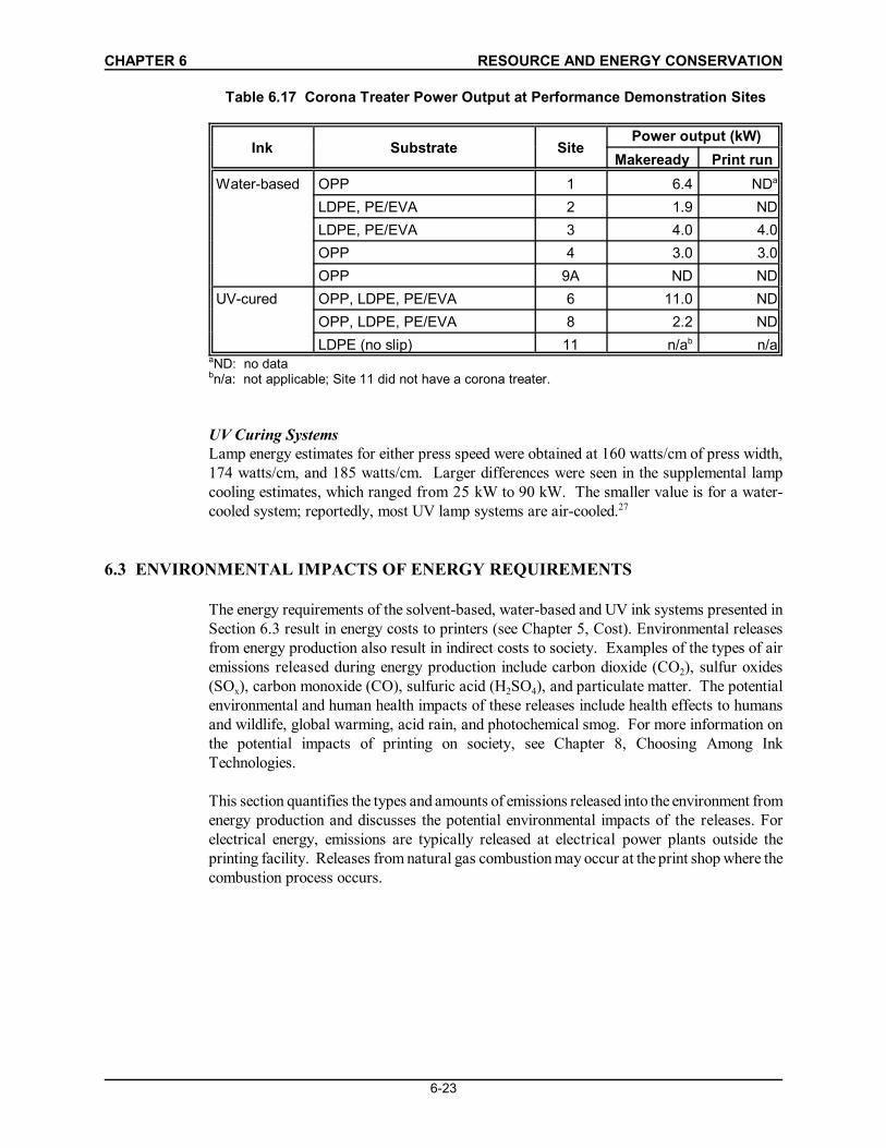
Table 6.17 presents power output data (e.g., power applied to the web) read by WMUrepresentatives from the corona treater power supply box during the performancedemonstration runs. In some cases, WMU representatives also measured power input in voltsand amps during the print run. However, these data are not reported because corona treatersuppliers have indicated they cannot be used to calculate power input in kilowatts withoutknowing site-specific power efficiency factors.26
CHAPTER 6 RESOURCE AND ENERGY CONSERVATION
6-23
Table 6.17 Corona Treater Power Output at Performance Demonstration Sites
aND: no data bn/a: not applicable; Site 11 did not have a corona treater.
UV Curing SystemsLamp energy estimates for either press speed were obtained at 160 watts/cm of press width,174 watts/cm, and 185 watts/cm. Larger differences were seen in the supplemental lampcooling estimates, which ranged from 25 kW to 90 kW. The smaller value is for a water-cooled system; reportedly, most UV lamp systems are air-cooled.27
6.3 ENVIRONMENTAL IMPACTS OF ENERGY REQUIREMENTS
The energy requirements of the solvent-based, water-based and UV ink systems presented inSection 6.3 result in energy costs to printers (see Chapter 5, Cost). Environmental releasesfrom energy production also result in indirect costs to society. Examples of the types of airemissions released during energy production include carbon dioxide (CO2), sulfur oxides(SOx), carbon monoxide (CO), sulfuric acid (H2SO4), and particulate matter. The potentialenvironmental and human health impacts of these releases include health effects to humansand wildlife, global warming, acid rain, and photochemical smog. For more information onthe potential impacts of printing on society, see Chapter 8, Choosing Among InkTechnologies.
This section quantifies the types and amounts of emissions released into the environment fromenergy production and discusses the potential environmental impacts of the releases. Forelectrical energy, emissions are typically released at electrical power plants outside theprinting facility. Releases from natural gas combustion may occur at the print shop where thecombustion process occurs.
CHAPTER 6 RESOURCE AND ENERGY CONSERVATION
6-24
Emissions from Energy Production
Energy-related emissions — both at and away from the facility — can be a significant partof the total life-cycle environmental impact of printing. Emissions are released from naturalgas-burning dryers and oxidizers as well as from the electricity generation process at offsitepower plants. The level of emissions can vary considerably among printing technologies,depending on the fuel type and process efficiency.
The emissions from energy production during the performance demonstrations were evaluatedusing a computer program developed by the EPA National Risk Management ResearchLaboratory.28 This program, which is called P2P-version 1.50214, can estimate the type andquantity of releases resulting from the production of energy, as long as the differences inenergy consumption and the source of the energy used (e.g., hydro-electric, coal, natural gas,etc.) are known. The program compares the pollution generated by different processes (e.g.,extraction and processing of coal or natural gas for fuel).
Electrical power derived from the average national power grid was selected as the source ofelectrical energy, and natural gas was used as the source of thermal energy for this evaluation.Energy consumption rates per 6,000 ft2 from Table 6.11 were used as the basis for theanalysis. It should be noted that the location of the environmental impacts will vary by energytype; natural gas releases will occur onsite, while electricity-related releases will occur atoffsite power plants.
Results of this analysis are presented in Table 6.18. Appendix 6-C contains printouts fromthe P2P program. Water-based systems generally had the lowest levels of emissions fromenergy production at either press speed, followed by solvent-based systems. The releasesassociated with the production of energy for the UV ink system exceeded those from water-based or solvent-based systems for every pollutant category except hydrocarbons.Hydrocarbon emissions were greater for the water-based and solvent-based systems, becauseof the natural gas consumed by the hot-air dryers used with these systems. Greater emissionsfrom energy production were seen at lower press speeds for all of the systems, due to thelonger run times needed to print a given quantity of substrate. However, as noted in Section6.2, data were not available for all equipment to estimate the differences in energy draw atdifferent press speeds. Emissions from energy production would be reduced if equipmentpowers down at decreased press speeds.
CH
APTE
R 6
R
ESO
UR
CE
AND
EN
ERG
Y C
ON
SER
VATI
ON
6-25
Tabl
e 6.
18 R
elea
ses
Due
to E
nerg
y Pr
oduc
tiona
Ink
Syst
em
Pres
sSp
eed
(fpm
)
Amou
nt R
elea
sed
(g/6
,000
ft2 )
Car
bon
Dio
xide
(CO
2)
Car
bon
Mon
oxid
e(C
O)
Dis
solv
edSo
lids
Hyd
roca
rbon
sN
itrog
enO
xide
s(N
Ox)
Part
icul
ates
Solid
Was
tes
Sulfu
rO
xide
s(S
Ox)
Sulfu
ricAc
id(H
2SO
4)
Solv
ent-
base
d50
09,
400
8.7
1.3
5526
8.0
570
443.
4
453
10,0
009.
61.
460
298.
863
048
3.8
Wat
er-
base
d50
06,
400
5.5
0.81
4116
4.8
340
262.
0
394
8,00
06.
81.
052
205.
941
033
2.5
UV-
cure
d50
016
,000
233.
020
7027
2,00
014
012
340
24,0
0033
4.5
2910
040
2,90
021
017
a Rel
ease
s fo
r sol
vent
- and
wat
er-b
ased
ink
syst
ems
are
expe
cted
to o
ccur
bot
h at
the
prin
ting
faci
lity
and
at th
e of
f-site
ele
ctric
ity g
ener
atio
n pl
ant;
rele
ases
from
the
UV-
cure
d in
k sy
stem
are
exp
ecte
d to
occ
ur e
xclu
sive
ly a
t the
ele
ctric
ity g
ener
atio
n pl
ant.
CHAPTER 6 RESOURCE AND ENERGY CONSERVATION
6-26
The higher overall emissions for UV systems were due primarily to the differences in fuelmixes used by the three systems (both electrical and natural gas energy for water-based andsolvent-based systems, as compared to electrical energy alone for UV). The U.S. electric gridis mainly comprised of coal, nuclear, hydroelectric, gas and petroleum-fired power plants. In 1997 the majority of U.S. electrical energy (57%) was produced from coal-firedgenerators,29 which tend to release greater quantities of emissions than gas-fired energysystems. For example, at a 500 fpm press speed, the UV system consumed an estimated 23kW-hr /6,000ft2 of electricity, which is equivalent to 78,000 Btu/6,000ft2. At the same pressspeed, the solvent-based system consumed an estimated 6.6 kW-hr/6,000ft2 of electricity plus78,000 Btu/6,000ft2 of natural gas, for a total of 100,000 Btu/6,000ft2 . However, althoughthe UV system consumed less overall energy than the solvent-based system, it still had higheremissions from energy production for the pollutants evaluated, except hydrocarbons.
Environmental Impacts of Energy Production
Table 6.19 lists the pollution categories, pollutant classes, and media of release assigned bythe P2P software. Table 6.20 lists total pollution generated by pollutant category and class,and Table 6.21 provides totals for each pollution category.
Based on the release rates shown in Tables 6.21 and 6.22, the water-based systems showedthe lowest potential environmental impacts from energy production, including human health,use impairment, or disposal capacity impacts, followed by solvent-based systems. The UVsystems had the greatest potential environmental impacts from energy production in each ofthe pollution categories and classes.
Limitations and Uncertainties
These release rates can only be used as indicators of relative potential impacts, not as anassessment of risk. Assessing risk from energy production also would require knowledge ofthe location and concentration of release, and proximity to surrounding populations. It wouldalso require more information on the specific chemicals emitted, for example the exact identityof the hydrocarbons emitted during natural gas combustion as compared to the hydrocarbonsemitted during coal combustion.
The potential environmental impacts of energy requirements for the three ink systems arebased on the energy estimates described in Section 6.2 and are subject to the same limitationsand uncertainties.
CHAPTER 6 RESOURCE AND ENERGY CONSERVATION
6-27
Table 6.19 Pollution Categories, Classes and Media of Release
Pollution Category Pollutant Class Chemicals AffectedResource
Human Health Impacts Toxic Inorganicsa Nitrogen oxides,sulfur oxides
a Dissolved solids are a measure of water purity and can negatively affect aquatic life as well as thefuture use of the water.b Toxic organic and inorganic pollutants can cause adverse health effects in humans and wildlife.c Particulate releases can promote respiratory illness in humans.
The program uses data reflecting the national average pollution releases per kilowatt-hourderived from particular sources. It does not account for differences in emission rates atdifferent power plants, nor does it necessarily account for the latest in pollution controltechnologies applied to power plant emissions.
The P2P program primarily accounts for emissions of pollutant categories and not emissionsof the individual chemicals or materials known to occur from energy production, such asmercury. Nor does it provide information on the spatial or temporal characteristics of releases.Thus, the P2P software provides emissions estimates in grams per functional unit (grams per6,000ft2 of printed surface, in this case) and assigns them to pollution (impact) categories andclasses to develop release rates by impact category. As discussed previously, these releaserates can be used as an indicator of relative potential environmental impacts, but are not anassessment of risk.
CH
APTE
R 6
R
ESO
UR
CE
AND
EN
ERG
Y C
ON
SER
VATI
ON
6-28
Tabl
e 6.
20 E
mis
sion
s G
ener
ated
by
Pollu
tant
Cat
egor
y an
d C
lass
Pollu
tion
Cat
egor
yPo
lluta
nt C
lass
Emis
sion
s G
ener
ated
by
Pollu
tant
Cat
egor
y an
d C
lass
a
(g/p
er 6
,000
ft2 )
Solv
ent
(500
fpm
)So
lven
t(4
53 fp
m)
Wat
er(5
00 fp
m)
Wat
er(3
94 fp
m)
UV
(500
fpm
)U
V(3
40 fp
m)
Hum
an H
ealth
Impa
cts
Toxi
c In
orga
nics
7077
4353
210
310
Toxi
c O
rgan
ics
8.7
9.6
5.5
6.8
2333
Use
Impa
irmen
tIm
pact
sAc
id R
ain
Prec
urso
rs70
7743
5321
031
0
Cor
rosi
ves
7381
4556
220
330
Dis
solv
ed S
olid
s4.
75.
22.
83.
515
22
Glo
bal W
arm
ers
9,40
010
,000
6,40
08,
000
16,0
0024
,000
Odo
rant
s55
6041
5220
29
Parti
cula
tes
8.0
8.8
4.8
5.9
2740
Smog
form
ers
9099
6379
110
170
Dis
posa
l Cap
acity
Impa
cts
Solid
Was
tes
570
630
340
410
2,00
02,
900
a All
num
bers
hav
e be
en ro
unde
d to
two
sign
ifica
nt fi
gure
s.
CHAPTER 6 RESOURCE AND ENERGY CONSERVATION
6-29
Table 6.21 Summary of Pollution Generated by Category
PollutionCategory
Pollution Generated a
(g/per 6,000ft2)
Solvent(500fpm)
Solvent(453fpm)
Water(500fpm)
Water(394fpm)
UV(500fpm)
UV(340fpm)
Human HealthImpacts
79 87 48 60 230 350
UseImpairmentImpacts
9,500 10,000 6,500 8,100 16,000 24,000
DisposalCapacityImpacts
570 630 340 410 2,000 2,900
OverallEnvironment
10,000 11,000 6,800 8,500 18,000 27,000
a All numbers have been rounded to two significant figures.
6.4 CLEAN-UP AND WASTE DISPOSAL PROCEDURES
This section of Chapter 6 discusses the types of cleaning solutions and clean-up methods usedfor the three different flexographic ink technologies studied in the CTSA performancedemonstrations, and describes the disposal procedures for the various types of wastesgenerated in each case.
All flexographic printing operations result in waste ink and substrate, soiled shop towels, andcleaning solutions that need to be disposed. However, the volume of waste ink and thespecific chemical makeup of wastes differ, depending on the type of ink system that a printeruses. Therefore, the clean-up methods, waste disposal procedures, and overall environmentalimpacts of a printing process also differ for each ink system.
Most printers employ the same basic procedures to clean solvent-based or water-based inkfrom a press. Excess ink may be wiped or scraped down and drained from the press. Thesystem is then flushed with a cleaning solution to remove additional ink and prepare the pressfor a fresh run. Shop towels, usually wetted with a cleaner, are used to wipe down the aniloxrolls, doctor blades, or other press parts. UV ink cleaning procedures are similar, except thatdifferent cleaners or dry shop towels may be used to wipe down the press.
Most solvent-based ink wastes are classified as hazardous waste and are disposed ofaccordingly. Water-based ink wastes, however, may or may not be classified as hazardouswaste. Although solvent-based waste disposal costs may be reduced because it can be burnedand used for heat production, this is not always possible with water-based wastes.Regulations prohibit hazardous waste from being mixed with fuel and burned if it has anenergy value of less than 5,000 Btu/lb.30 Therefore, some printers using low-solventwater-based inks use an "ink splitter" to separate the solids from fluids in their waste ink and
CHAPTER 6 RESOURCE AND ENERGY CONSERVATION
6-30
cleaning solutions. This substantially reduces the amount of hazardous waste that needs tobe disposed. The waste water usually can be reused in-house or discharged to the public watersystem, but if the original waste qualified as hazardous, the solids also will need to be treatedas hazardous waste. (See the Control Options section of Chapter 7 for more information onink splitters.)
Multi-day runs of UV-cured printing may generate less ink waste than solvent-based or water-based printing for printers who shut down overnight, such as some smaller printers. In thiscase, the ink can remain indefinitely on the press or in the reservoirs without curing on pressparts or the sump.31 The press is shut down, the ink reservoirs should be covered to preventdust from getting in, and the press is turned on to resume printing the next day. Also, becausecorrect color adjustment is achieved more quickly at the beginning of a UV run using processcolors on dedicated stations, under these conditions UV may generate somewhat less wasteof ink and substrate. However, because UV inks are too thick to be modified easily, correctcolor adjustment may not be achieved more quickly when using matched/Pantone colors thatrequire toning.32
Press Clean-Up and Waste Reduction in the CTSA Performance Demonstrations
Table 6.22 summarizes the types of cleaning solutions used at the performance demonstrationsites. For solvent-based systems, three sites utilized a blend of alcohol and acetate solutions,and one site reported using alcohol alone. The cleaning solutions used for UV-systems werethe same as those for solvent-based systems, except for one site that used analcohol/water/soap blend. Water, at times mixed with a little alcohol and/or ammonia, wasused for clean-up of the water-based ink systems.
Table 6.22 Cleaning Solutions Used at Performance Demonstration Sites
The clean-up and waste disposal procedures employed at the performance demonstration sitesare summarized in Table 6.23. Appendix 6-B describes these procedures in more detail. Allbut one site employed reusable shop towels to clean the press. All sites recycled some or allof their waste substrate.
CHAPTER 6 RESOURCE AND ENERGY CONSERVATION
6-31
Table 6.23 Clean-up and Waste Disposal Procedures at PerformanceDemonstration Sites
Ink System Shop Towels Ink and Cleaning SolutionDisposition
WasteSubstrate
Disposition
Solvent-based Sent to industriallaundry (3 sites)Landfilled ( 1site)
Solvent mix to cement kiln (1site)On-site distillation; still bottomsto cement kiln (1 site)Reused 3 times then disposedas hazardous waste (1 site)No data (1 site)
Partially or allrecycled(4 sites)
Water-based Sent to industriallaundry (5 sites)
Mixture incinerated (2 sites)Separated water and solids;incinerated solids (2 sites)Diluted mixture and dischargedto POTW (1 site)
Partially or allrecycled(5 sites)
UV-cured Sent to industriallaundry (2 sites)No data (1 site)
Reused once before sending tocement kiln (1 site)On-site distillation; still bottomsdisposed (1 site)No data (1 site)
Partially or allrecycled(3 sites)
CHAPTER 6 RESOURCE AND ENERGY CONSERVATION
6-32
1. Barnard, Harris. 1998a. Kidder, Inc. Personal communication with Lori Kincaid, University ofTennessee Center for Clean Products and Clean Technologies. April 24, 1998.
2. Barnard, Harris. 1998b. Kidder, Inc. Personal communication with Lori Kincaid, University ofTennessee Center for Clean Products and Clean Technologies. April 30, 1998.
3. Ibid.
4. Ibid.
5. Ibid.
6. Barnard, Harris. 1998d. Kidder, Inc. Personal communication with Lori Kincaid, University ofTennessee Center for Clean Products and Clean Technologies. May 12, 1998.
7. Reschke, Darren. 1998. MEGTEC Systems [formerly Wolverine (Massachusetts) Corporation].Personal communication with Lori Kincaid, University of Tennessee Center for Clean Productsand Clean Technologies. May 18, 1998.
8. Ibid.
9. Foundation of Flexographic Technical Association. 1999. Flexography: Principles andPractices, 5th ed. Volume 3. Ronkonkoma, NY: Foundation of Flexographic Technical Association.
10. Kottke, Lee. Anguil Environmental Systems, Inc. Personal communication with Trey Kellett, AbtAssociates. August 2, 2000.
11. Bemi, Dan and Steve Rach. MEGTEC Systems. Personal communication with Trey Kellett, AbtAssociates. July 14, 2000.
12. Enercon Industries Incorporated. Not dated. “Corona Treatment,”http://www.enerconind.com/surface/papers/overview.
13. Flathmann, Kurt. 1998a. Fischer & Krecke, Inc. Personal communication with Lori Kincaid,University of Tennessee Center for Clean Products and Clean Technologies. June 1, 1998.
14. Flathmann, Kurt. 1998a. Op. cit. June 1, 1998.
15. Ibid.
16. Barnard, Harris. 1998c. Kidder, Inc. Personal communication with Lori Kincaid, University ofTennessee Center for Clean Products and Clean Technologies. May 1, 1998.
17. Ibid.
18. Ibid.
REFERENCES
CHAPTER 6 RESOURCE AND ENERGY CONSERVATION
6-33
19. Ibid.
20. Kottke, Lee. 1998. Anguil Environmental, Inc. Personal communication with Lori Kincaid,University of Tennessee Center for Clean Products and Clean Technologies. May 8, 1998.
21. Reschke, Darren. 1998. Op. cit. May 18, 1998.
22. Smith, Alan. 1998. SOA International, Inc. Personal communication with Lori Kincaid,University of Tennessee Center for Clean Products and Clean Technologies. June 3, 1998.
23. Gilbertson, Tom. 1998. Enercon Industries, Inc. Personal communication with Lori Kincaid,University of Tennessee Center for Clean Products and Clean Technologies. May 18, 1998.
24. Smith, Alan. 1998. Op. cit. June 3, 1998.
25. Gilbertson, Tom. 1998. Op. cit. May 18, 1998.
26. Markgraf, David. 1998. Enercon Industries, Inc. Personal communication with Lori Kincaid,University of Tennessee Center for Clean Products and Clean Technologies. May 11, 1998.
27. Flathmann, Kurt. 1998b. Op cit. June 3, 1998.
28. U.S. EPA. 1994. P2P-Version 1.50214 computer software program. Office of Research andDevelopment, National Risk Management Research Laboratory.
29. Energy Information Administration. 1999. Electric Power Monthly, February 1999 (with data forNovember 1998), DOE/EIA- 0223(99/02).
30. Ellison, David. 2001. Pechiney Plastic Packaging. Personal communication with TreyKellett, Abt Associates Inc. September 26, 2001.
31. Ross, Alexander. 1999. RadTech. Personal communication with Trey Kellett, Abt Associates. June 9, 1999.
32. Shapiro, Fred. 2000. P-F Technical Services. Personal communication with Lori Kincaid,University of Tennessee Center for Clean Products and Clean Technologies. February 22, 2000.