48
1 ICE3003: Computer Architecture | Spring 2014 | Euiseong Seo ([email protected]) Chapter 6 Storage and Other I/O Topics

1 ICE3003: Computer Architecture | Spring 2014 | Euiseong Seo ([email protected])
Chapter 6
Storage and Other I/O Topics

2 ICE3003: Computer Architecture | Spring 2014 | Euiseong Seo ([email protected])
Introduction § I/O devices can be characterized by
• Behaviour: input, output, storage • Partner: human or machine • Data rate: bytes/sec, transfers/sec
§ I/O bus connections
§6.1 Introduction

3 ICE3003: Computer Architecture | Spring 2014 | Euiseong Seo ([email protected])
I/O System Characteristics § Dependability is important
• Particularly for storage devices § Performance measures
• Latency (response time) • Throughput (bandwidth) • Desktops & embedded systems
– Mainly interested in response time & diversity of devices • Servers
– Mainly interested in throughput & expandability of devices

4 ICE3003: Computer Architecture | Spring 2014 | Euiseong Seo ([email protected])
Dependability
§ Fault: failure of a component • May or may not
lead to system failure
§6.2 Dependability, R
eliability, and Availability
Service accomplishment Service delivered
as specified
Service interruption Deviation from
specified service
Failure Restoration

5 ICE3003: Computer Architecture | Spring 2014 | Euiseong Seo ([email protected])
Dependability Measures § Reliability: mean time to failure (MTTF) § Service interruption:
mean time to repair (MTTR) § Mean time between failures
• MTBF = MTTF + MTTR
§ Availability = MTTF / (MTTF + MTTR) § Improving Availability
• Increase MTTF: fault avoidance, fault tolerance, fault forecasting
• Reduce MTTR: improved tools and processes for diagnosis and repair

6 ICE3003: Computer Architecture | Spring 2014 | Euiseong Seo ([email protected])
Disk Storage § Nonvolatile, rotating magnetic storage
§6.3 Disk S
torage

7 ICE3003: Computer Architecture | Spring 2014 | Euiseong Seo ([email protected])
Disk Sectors and Access § Each sector records
• Sector ID • Data (512 bytes, 4096 bytes proposed) • Error correcting code (ECC)
– Used to hide defects and recording errors • Synchronization fields and gaps
§ Access to a sector involves • Queuing delay if other accesses are pending • Seek: move the heads • Rotational latency • Data transfer • Controller overhead

8 ICE3003: Computer Architecture | Spring 2014 | Euiseong Seo ([email protected])
Disk Access Example § Given
• 512B sector, 15,000rpm, 4ms average seek time, 100MB/s transfer rate, 0.2ms controller overhead, idle disk
§ Average read time • 4ms seek time
+ ½ / (15,000/60) = 2ms rotational latency + 512 / 100MB/s = 0.005ms transfer time + 0.2ms controller delay = 6.2ms
§ If actual average seek time is 1ms • Average read time = 3.2ms

9 ICE3003: Computer Architecture | Spring 2014 | Euiseong Seo ([email protected])
Disk Performance Issues § Manufacturers quote average seek time
• Based on all possible seeks • Locality and OS scheduling lead to
smaller actual average seek times § Smart disk controller allocate physical sectors
on disk • Present logical sector interface to host • SCSI, ATA, SATA
§ Disk drives include caches • Prefetch sectors in anticipation of access • Avoid seek and rotational delay
10 ICE3003: Computer Architecture | Spring 2014 | Euiseong Seo ([email protected])
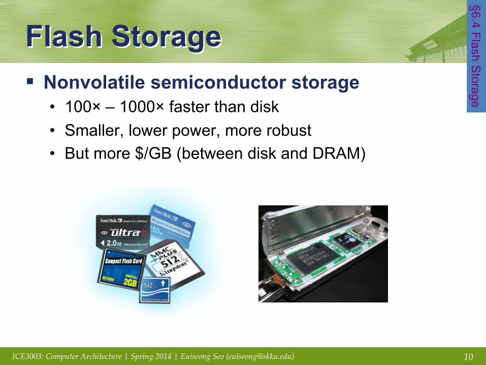
Flash Storage § Nonvolatile semiconductor storage
• 100× – 1000× faster than disk • Smaller, lower power, more robust • But more $/GB (between disk and DRAM)
§6.4 Flash Storage

11 ICE3003: Computer Architecture | Spring 2014 | Euiseong Seo ([email protected])
Flash Types § NOR flash: bit cell like a NOR gate
• Random read/write access • Used for instruction memory in embedded systems
§ NAND flash: bit cell like a NAND gate • Denser (bits/area), but block-at-a-time access • Cheaper per GB • MLC vs SLC • Used for USB keys, media storage, …
§ Flash bits wears out after 1000’s of accesses • Not suitable for direct RAM or disk replacement • Wear leveling: remap data to less used blocks
12 ICE3003: Computer Architecture | Spring 2014 | Euiseong Seo ([email protected])
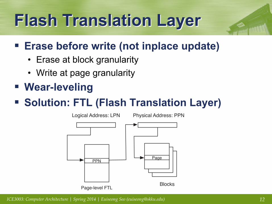
Flash Translation Layer § Erase before write (not inplace update)
• Erase at block granularity • Write at page granularity
§ Wear-leveling § Solution: FTL (Flash Translation Layer)
on the underlying FTL algorithms and implementation details. Thismapping table is accessed in every request and should be main-tained when the storage system is powered off. Therefore, thememory for this translation mapping table should be stored in fastand non-volatile media such as battery-backed DRAM or battery-backed SRAM. Because battery-backed DRAM is also a significantpower consumer, the memory component for storing the mappingtable is also suspected to contribute to the power consumption offlash-based SSDs
2.2. Flash translation layer
The FTL maintains a mapping table of virtual sector numbers,which are seen from the host system, to physical sector numbersof the flash memory. It emulates the functionality of a normalblock device by exposing only read/write operations to the uppersoftware layers and hiding the presence of the erase operation.
Processing read requests in the FTL is simple. When the read re-quest occurs from the host system, the FTL returns the correspond-ing physical sector number after searching the mapping table.
In comparison to processing read requests, write requests in-duce a complex update process. Basically, the sequence of process-ing write requests is as follows; (i) find a suitable erased page to bewritten, (ii) write the new data over the chosen page, (iii) invali-date the original page mapped to the logical page currently in pro-cess, if it exists, and (iv) update the mapping table to reflect thischange.
FTL algorithms can be roughly categorized into three groups bytheir mapping granularity.
The page-mapping algorithm [16], which is a basic form of theFTL, uses a translation table, which translates external logical pageaddresses into internal physical page addresses on the flash
memory as shown in Fig. 2(a). Because the granularity of each en-try is a page, each mapping entry implies an one-to-one mappingrelationship from a logical page to the corresponding physicalpage. When the overwriting operation occurs, the FTL only needsto remap the corresponding entry.
By using this straightforward table management, the page-mapping algorithm has a fast translation speed and simple page-update mechanism, which only changes the mapping entry forthe page being updated. However, because there should be asmany mapping entries as the number of pages, the mapping tabletakes a large amount of space, which we will explore in Section 3.3.
Therefore, the block-mapping algorithm [29] and its variantswere proposed. As shown in Fig. 2(b), the mapping table in theblock-mapping FTL only contains the block granularity mappingentries, each of which maps a logical page address to the combina-tion of a physical block number and an offset number. The actualphysical page, which stores the data for the logical page, is deter-mined by the offset field of the logical page addresses in the block.
Although the table size of the block-mapping FTL is very small,processing partial rewrites of previously written blocks induces asubstantial amount of copy and erase operations. This is because,in order to overwrite a page, a new free block has to be allocated,and all the pages, except the page to be overwritten in the originalblock, have to be copied over to the pages with the same offsets inthe new block.
Therefore, the hybrid FTL (also known as the log-based FTL)[19,23], illustrated in Fig. 3 has gained popularity [17] in commod-ity flash-based storage devices, of which production cost is of thehighest priority.
The hybrid FTL has a few spare blocks, called log blocks, whichare used as temporary space for the updated pages. When a pageoverwrite operation occurs, a free page in the log blocks is
Fig. 1. Block-diagram of a typical SSD inside [3].
Fig. 2. Address translation in the page-mapping and block-mapping FTL.
356 S. Park et al. / Journal of Systems Architecture 57 (2011) 354–365
13 ICE3003: Computer Architecture | Spring 2014 | Euiseong Seo ([email protected])
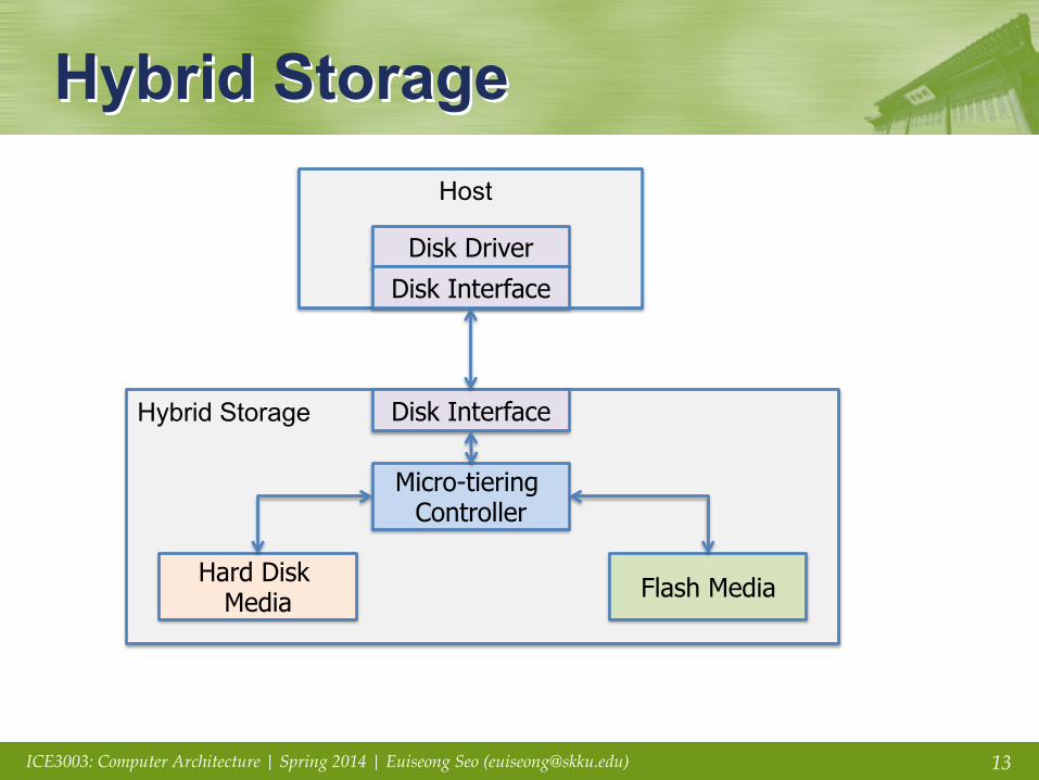
Hybrid Storage Host
Disk Driver
Disk Interface
Hybrid Storage Disk Interface
Micro-tiering Controller
Hard Disk Media Flash Media

14 ICE3003: Computer Architecture | Spring 2014 | Euiseong Seo ([email protected])
Hybrid Storage § Conceptual Benefit
• Large capacity of HDDs with high performance of SSDs • Low power at most of time
§ Reality • What to put in each media? • When? At what granularity? • Complex metadata management

15 ICE3003: Computer Architecture | Spring 2014 | Euiseong Seo ([email protected])
Flash Cache
FlashTier: A Lightweight, Consistent and Durable Storage Cache Mohit Saxena, Michael M. Swift and Yiying Zhang
Introduction High-speed solid-state drives (SSDs) composed of NAND flash are often deployed as a cache in front of high-capacity disk storage. Several vendors adopt SSDs as a block cache transparent to filesystems: • OS Vendors: Oracle, Microsoft, Linux • Storage Vendors: Intel, OCZ, NetApp, EMC, FusionIO • Applications: Facebook, Google
Unified Address Space Consistent Cache Interface
Problem Statement Design Overview The FlashTier system consists of two components: a solid-state cache (SSC), a flash device designed specifically for caching, and a cache manager within the OS for migrating data between the flash caching tier and disk storage.
References [1] N. Agrawal, V. Prabhakran, T. Wobber, J. Davis, M. Manasse, and R. Panigraphy. Design Tradeoffs for SSD performance, In Usenix ATC 2008. [2] Facebook FlashCache,https://github.com/facebook/flashcache. [3] Google Inc, Sparse Hash Map,http://goog-sparsehash.sourceforge.net [4] M. Saxena and M. Swift, FlashVM: Virtual Memory Management on Flash, In Usenix ATC 2010.
Inefficiencies with SSD block cache Address Space Management
Two levels of indirections for address translation
Consistency and Durability
Several hours to days for warm-up after reboot/crash
Free Space Management
Low write performance and endurance due to garbage collection for caching
Two levels of indirection: On an SSD cache, the cache manager maintains a mapping table within the host DRAM translating disk addresses to SSD addresses. The SSD block cache keeps another mapping (FTL) within the device memory translating SSD logical addresses to flash addresses to avoid in-place writes. These two mappings pose memory overhead for host DRAM and device memory.
Inconsistency: On an SSD cache, maintaining cached data consistent and durable requires the cache manager to persist the cache block state and mapping within the host DRAM. To avoid the runtime cost of persisting the mapping, most cache managers do not provide any consistency or durability. • Without durability, filling a 100GB cache from a 500 IOPS disk
system can take over 14 hours after a reboot. • Without consistency, cache update and invalidate operations
can result in a stale copy of cached data to be read later. FlashTier provides an SSC interface to keep the mapping consistent and durable.
Free Space Management
Garbage collection: On an SSD cache, garbage collection result in additional copies for valid pages to create free erased blocks for new writes. • Full devices lacking free
blocks behave worse with up to 83% lower performance and 80% lower write endurance [Intel IDF ‘10].
• Caches are often full.
Application
Cache Manager
Block Layer
Read Read miss
Write Write through
File System
Discard Write back SSD
Cache Manager
SSC Disks
OS
Application
Cache Manager
Block Layer File System
Cache Manager
SSD
Flash Translation Layer
Mapping Table
0
200
400
600
800
0
20
40
60
80
100HostDevice
Write Intensive Read Intensive
Tota
l Mem
ory
(MB)
Disk LBN
LBN Æ PBA
Cache Manager
Sparse Hash Map
lookup, insert, remove
Data Blocks
read/write
OS
Cache Manager
Ap
plic
atio
n
Bloc
k La
yer
File
Syst
em
SSD
Flash Translation Layer
Command Purpose write-dirty Insert new block or update existing block with
dirty data. write-clean Insert new block or update existing block with
clean data. read Read block if present or return error evict Invalidate block immediately clean Allow future eviction of block exists Test for presence of dirty blocks
% T
hrou
ghpu
t rel
ativ
e to
Non
e
Write Intensive Read Intensive
81 71
96 97 85
93 96 97
0
20
40
60
80
100
120
mail homes usr proj
None SSD WB SSC WB SSC Dirty
SSD: 5 reads/writes
Stale Stale
Valid
Valid
Stale Stale
Stale Valid
Valid
Free Free
Free Free
Free
Valid
Valid
Valid Valid
Valid Valid
Stale Stale
Clean Dirty
Dirty
Stale Stale
Stale Clean
Clean
Stale Stale
Clean Dirty
Dirty
Free Free
Free Free
Free
SSC: No reads/writes
Log Data
SSC
Evict GC
Log Data
Convert
Convert
SSC-V
Evict GC
201%
268%
98% 99%
0
50
100
150
200
250
300
homes mail usr proj
SSDSSC WTSSC-V WTSSC WBSSC-V WB
Perfo
rman
ce re
lativ
e to
SSD
WB
Write Intensive Read Intensive
Silent Eviction: An SSC employs silent eviction to lose clean data rather than copying it. It uses a cost/benefit mechanism to select blocks for eviction: • Usage benefit: The cache
manager uses evict/clean to identify cold clean data.
• Eviction cost: The SSC silently evicts least-utilized cold clean data.
Caching is different from Storage An SSD block cache is hindered by the narrow block interface and internal block management of SSDs designed to serve as a disk replacement for persistent storage.
SSD block cache
SSC: The SSC matches the requirements of caching behavior. It provides: • Unified cache address space • Consistent cache interface • Cache-aware free space
management Cache Manager in OS: • Adapts to the new interface of
the SSC • Operation Modes: write-back for
higher performance or write-through for higher safety
FlashTier Unified Address Space • The cache manager directly
addresses flash blocks in the SSC by disk LBN.
• The SSC only stores the hot data out of the terabytes of disk storage. As a result, the SSC optimizes for sparse address space using a Sparse Hash Map [3] requiring only 8.4 bytes/key to keep low device memory footprint.
Host and Device Memory Usage The graph shows the host and device memory usage for SSD cache and FlashTier with SSC and SSC-V. • The SSD cache manager stores state for all cached blocks. • The FlashTier cache manager only maintains a dirty block
table to clean/flush dirty LRU blocks to disk on exceeding the dirty mark.
• SSC-V stores more page-level mappings for variable log space and improved performance.
FlashTier reduces memory usage for host and device combined by 78% for SSC and 60% for SSC-V relative to SSD block cache.
Consistent SSC Interface
Cost of Crash Consistency The graph shows the relative cost of consistency for SSD block cache persisting dirty pages, SSC persisting both clean and dirty pages, and SSC Dirty persisting only dirty pages. The SSD block cache manager uses synchronous metadata updates, and the SSC uses internal logging and checkpointing mechanisms for persistent mapping.
Crash Guarantees: An SSC never returns stale data or loses dirty data. This is guaranteed by consistent reads following a cache write to dirty/clean data and cache eviction. It is always safe for the cache manager to consult the SSC after a crash.
FlashTier decreases the cost of crash consistency relative to the SSD block cache. It has less than 16% overhead for all workloads.
• SSC with fixed log space: Evicted data blocks are recycled for use as data blocks.
• SSC-V with variable log space: Evicted data blocks can be recycled for use as data blocks or increase the fraction of log blocks.
Policies for Silent Eviction The SSC uses two different policies for silently evicting a data block, which trade between cache performance and device memory for storing page-level mappings of log blocks:
System Performance The graph shows the relative performance of SSC and SSC-V in write-back and write-through modes relative to SSD cache in write-back mode.
FlashTier improves cache performance for write-intensive workloads by 168% with SSC-V and 101% with SSC. For read-intensive workloads, FlashTier
performs equally well as SSD block cache despite silent evictions.
16 ICE3003: Computer Architecture | Spring 2014 | Euiseong Seo ([email protected])
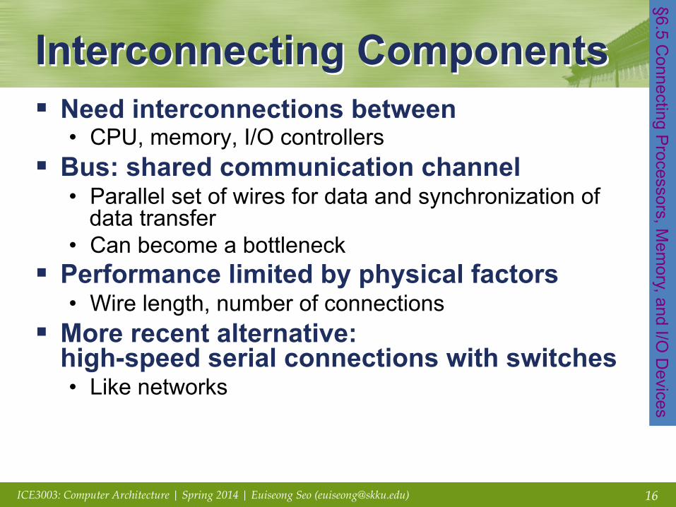
Interconnecting Components § Need interconnections between
• CPU, memory, I/O controllers § Bus: shared communication channel
• Parallel set of wires for data and synchronization of data transfer
• Can become a bottleneck § Performance limited by physical factors
• Wire length, number of connections § More recent alternative:
high-speed serial connections with switches • Like networks
§6.5 Connecting P
rocessors, Mem
ory, and I/O D
evices

17 ICE3003: Computer Architecture | Spring 2014 | Euiseong Seo ([email protected])
Bus Types § Processor-Memory buses
• Short, high speed • Design is matched to memory organization
§ I/O buses • Longer, allowing multiple connections • Specified by standards for interoperability • Connect to processor-memory bus through a bridge

18 ICE3003: Computer Architecture | Spring 2014 | Euiseong Seo ([email protected])
Bus Signals and Synchronization § Data lines
• Carry address and data • Multiplexed or separate
§ Control lines • Indicate data type, synchronize transactions
§ Synchronous • Uses a bus clock
§ Asynchronous • Uses request/acknowledge control lines for
handshaking

19 ICE3003: Computer Architecture | Spring 2014 | Euiseong Seo ([email protected])
I/O Bus Examples Firewire USB 2.0 PCI Express Serial ATA Serial
Attached SCSI
Intended use External External Internal Internal External Devices per channel
63 127 1 1 4
Data width 4 2 2/lane 4 4 Peak bandwidth
50MB/s or 100MB/s
0.2MB/s, 1.5MB/s, or 60MB/s
250MB/s/lane 1×, 2×, 4×, 8×, 16×, 32×
300MB/s 300MB/s
Hot pluggable
Yes Yes Depends Yes Yes
Max length 4.5m 5m 0.5m 1m 8m Standard IEEE 1394 USB
Implementers Forum
PCI-SIG SATA-IO INCITS TC T10
20 ICE3003: Computer Architecture | Spring 2014 | Euiseong Seo ([email protected])
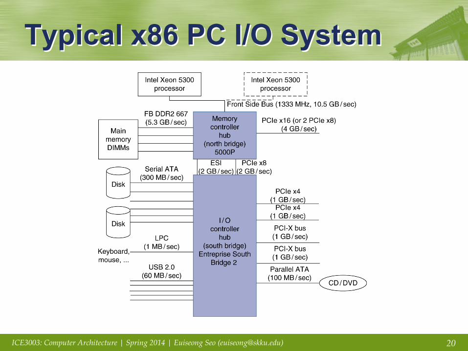
Typical x86 PC I/O System

21 ICE3003: Computer Architecture | Spring 2014 | Euiseong Seo ([email protected])
I/O Management § I/O is mediated by the OS
• Multiple programs share I/O resources – Need protection and scheduling
• I/O causes asynchronous interrupts – Same mechanism as exceptions
• I/O programming is fiddly – OS provides abstractions to programs
§6.6 Interfacing I/O D
evices …
22 ICE3003: Computer Architecture | Spring 2014 | Euiseong Seo ([email protected])
I/O Commands § I/O devices are managed by
I/O controller hardware • Transfers data to/from device • Synchronizes operations with software
§ Command registers • Cause device to do something
§ Status registers • Indicate what the device is doing and occurrence of
errors § Data registers
• Write: transfer data to a device • Read: transfer data from a device
23 ICE3003: Computer Architecture | Spring 2014 | Euiseong Seo ([email protected])
I/O Register Mapping § Memory mapped I/O
• Registers are addressed in same space as memory • Address decoder distinguishes between them • OS uses address translation mechanism to make them
only accessible to kernel § I/O instructions
• Separate instructions to access I/O registers • Can only be executed in kernel mode • Example: x86
24 ICE3003: Computer Architecture | Spring 2014 | Euiseong Seo ([email protected])
Polling § Periodically check I/O status register
• If device ready, do operation • If error, take action
§ Common in small or low-performance real-time embedded systems • Predictable timing • Low hardware cost
§ In other systems, wastes CPU time

25 ICE3003: Computer Architecture | Spring 2014 | Euiseong Seo ([email protected])
Interrupts § When a device is ready or error occurs
• Controller interrupts CPU § Interrupt is like an exception
• But not synchronized to instruction execution • Can invoke handler between instructions • Cause information often identifies
the interrupting device § Priority interrupts
• Devices needing more urgent attention get higher priority
• Can interrupt handler for a lower priority interrupt

26 ICE3003: Computer Architecture | Spring 2014 | Euiseong Seo ([email protected])
I/O Data Transfer § Polling and interrupt-driven I/O
• CPU transfers data between memory and I/O data registers
• Time consuming for high-speed devices
§ Direct memory access (DMA) • OS provides starting address in memory • I/O controller transfers to/from memory autonomously • Controller interrupts on completion or error
27 ICE3003: Computer Architecture | Spring 2014 | Euiseong Seo ([email protected])
DMA/Cache Interaction § If DMA writes to a memory block
that is cached • Cached copy becomes stale
§ If write-back cache has dirty block, and DMA reads memory block • Reads stale data
§ Need to ensure cache coherence • Flush blocks from cache if they will be used for DMA • Or use non-cacheable memory locations for I/O

28 ICE3003: Computer Architecture | Spring 2014 | Euiseong Seo ([email protected])
DMA/VM Interaction § OS uses virtual addresses for memory
• DMA blocks may not be contiguous in physical memory § Should DMA use virtual addresses?
• Would require controller to do translation § If DMA uses physical addresses
• May need to break transfers into page-sized chunks • Or chain multiple transfers • Or allocate contiguous physical pages for DMA

29 ICE3003: Computer Architecture | Spring 2014 | Euiseong Seo ([email protected])
Measuring I/O Performance § I/O performance depends on
• Hardware: CPU, memory, controllers, buses • Software: operating system,
database management system, application • Workload: request rates and patterns
§ I/O system design can trade-off between response time and throughput • Measurements of throughput often done with
constrained response-time
§6.7 I/O P
erformance M
easures: …
30 ICE3003: Computer Architecture | Spring 2014 | Euiseong Seo ([email protected])
Transaction Processing Benchmarks § Transactions
• Small data accesses to a DBMS • Interested in I/O rate, not data rate
§ Measure throughput • Subject to response time limits and failure handling • ACID (Atomicity, Consistency, Isolation, Durability) • Overall cost per transaction
§ Transaction Processing Council (TPC) benchmarks (www.tpc.org) • TPC-APP: B2B application server and web services • TCP-C: on-line order entry environment • TCP-E: on-line transaction processing for brokerage firm • TPC-H: decision support — business oriented ad-hoc queries

31 ICE3003: Computer Architecture | Spring 2014 | Euiseong Seo ([email protected])
File System & Web Benchmarks § SPEC System File System (SFS)
• Synthetic workload for NFS server, based on monitoring real systems
• Results – Throughput (operations/sec) – Response time (average ms/operation)
§ SPEC Web Server benchmark • Measures simultaneous user sessions,
subject to required throughput/session • Three workloads: Banking, Ecommerce, and Support
32 ICE3003: Computer Architecture | Spring 2014 | Euiseong Seo ([email protected])
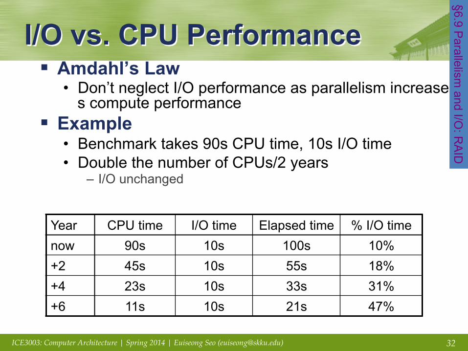
I/O vs. CPU Performance § Amdahl’s Law
• Don’t neglect I/O performance as parallelism increases compute performance
§ Example • Benchmark takes 90s CPU time, 10s I/O time • Double the number of CPUs/2 years
– I/O unchanged
Year CPU time I/O time Elapsed time % I/O time now 90s 10s 100s 10% +2 45s 10s 55s 18% +4 23s 10s 33s 31% +6 11s 10s 21s 47%
§6.9 Parallelism
and I/O: R
AID
33 ICE3003: Computer Architecture | Spring 2014 | Euiseong Seo ([email protected])
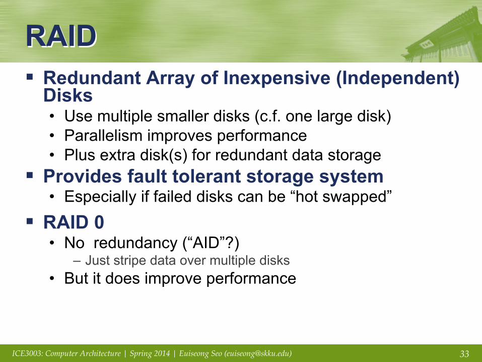
RAID § Redundant Array of Inexpensive (Independent)
Disks • Use multiple smaller disks (c.f. one large disk) • Parallelism improves performance • Plus extra disk(s) for redundant data storage
§ Provides fault tolerant storage system • Especially if failed disks can be “hot swapped”
§ RAID 0 • No redundancy (“AID”?)
– Just stripe data over multiple disks • But it does improve performance
34 ICE3003: Computer Architecture | Spring 2014 | Euiseong Seo ([email protected])
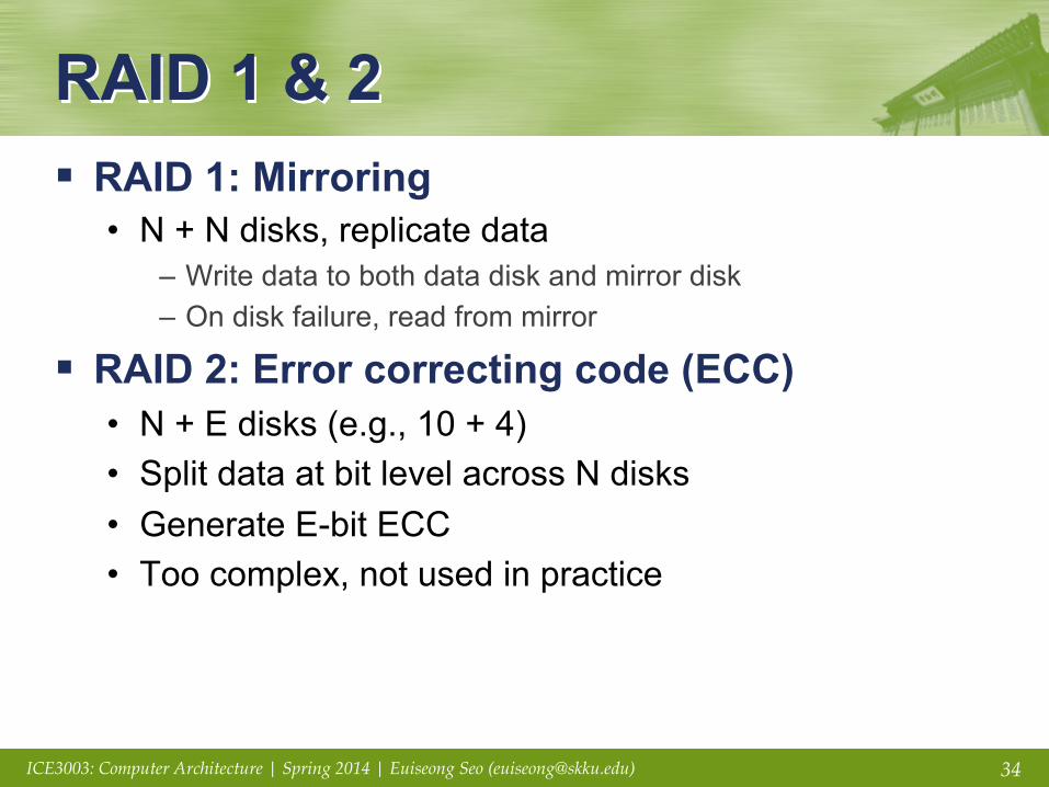
RAID 1 & 2 § RAID 1: Mirroring
• N + N disks, replicate data – Write data to both data disk and mirror disk – On disk failure, read from mirror
§ RAID 2: Error correcting code (ECC) • N + E disks (e.g., 10 + 4) • Split data at bit level across N disks • Generate E-bit ECC • Too complex, not used in practice

35 ICE3003: Computer Architecture | Spring 2014 | Euiseong Seo ([email protected])
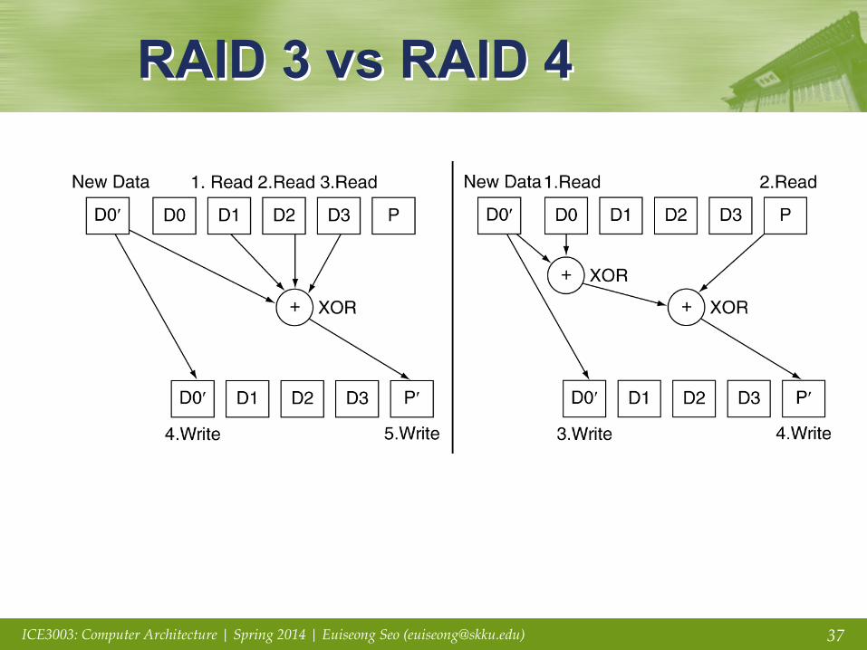
RAID 3: Bit-Interleaved Parity § N + 1 disks
• Data striped across N disks at byte level • Redundant disk stores parity • Read access
– Read all disks
• Write access – Generate new parity and update all disks
• On failure – Use parity to reconstruct missing data
§ Not widely used
36 ICE3003: Computer Architecture | Spring 2014 | Euiseong Seo ([email protected])
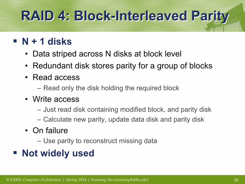
RAID 4: Block-Interleaved Parity
§ N + 1 disks • Data striped across N disks at block level • Redundant disk stores parity for a group of blocks • Read access
– Read only the disk holding the required block
• Write access – Just read disk containing modified block, and parity disk – Calculate new parity, update data disk and parity disk
• On failure – Use parity to reconstruct missing data
§ Not widely used

38 ICE3003: Computer Architecture | Spring 2014 | Euiseong Seo ([email protected])
RAID 5: Distributed Parity § N + 1 disks
• Like RAID 4, but parity blocks distributed across disks – Avoids parity disk being a bottleneck
§ Widely used

39 ICE3003: Computer Architecture | Spring 2014 | Euiseong Seo ([email protected])
RAID 6: P + Q Redundancy § N + 2 disks
• Like RAID 5, but two lots of parity • Greater fault tolerance through more redundancy
§ Multiple RAID • More advanced systems give similar fault tolerance wit
h better performance

40 ICE3003: Computer Architecture | Spring 2014 | Euiseong Seo ([email protected])
RAID Summary § RAID can improve performance and
availability • High availability requires hot swapping
§ Assumes independent disk failures • Too bad if the building burns down!
§ JBOD (Just a Bunch of Disks) • An alternative solution to RAID

41 ICE3003: Computer Architecture | Spring 2014 | Euiseong Seo ([email protected])
I/O System Design § Satisfying latency requirements
• For time-critical operations • If system is unloaded
– Add up latency of components
§ Maximizing throughput • Find “weakest link” (lowest-bandwidth component) • Configure to operate at its maximum bandwidth • Balance remaining components in the system
§ If system is loaded, simple analysis is insufficient • Need to use queuing models or simulation
§6.8 Designing and I/O
System
42 ICE3003: Computer Architecture | Spring 2014 | Euiseong Seo ([email protected])
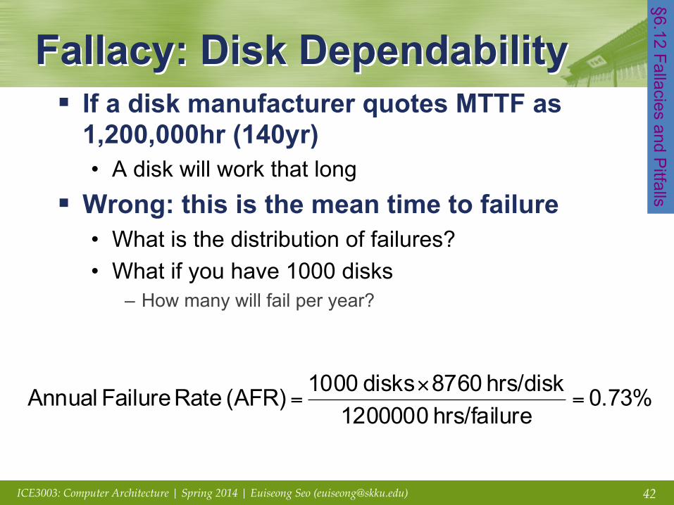
Fallacy: Disk Dependability § If a disk manufacturer quotes MTTF as
1,200,000hr (140yr) • A disk will work that long
§ Wrong: this is the mean time to failure • What is the distribution of failures? • What if you have 1000 disks
– How many will fail per year?
§6.12 Fallacies and Pitfalls
0.73%ehrs/failur 1200000
hrs/disk 8760disks 1000(AFR) Rate Failure Annual =×
=

43 ICE3003: Computer Architecture | Spring 2014 | Euiseong Seo ([email protected])
Fallacies § Disk failure rates are as specified
• Studies of failure rates in the field – Schroeder and Gibson: 2% to 4% vs. 0.6% to 0.8% – Pinheiro, et al.: 1.7% (first year) to 8.6% (third year) vs. 1.5%
• Why?
§ A 1GB/s interconnect transfers 1GB in one sec • But what’s a GB? • For bandwidth, use 1GB = 109 B • For storage, use 1GB = 230 B = 1.075×10⁹ B • So 1GB/sec is 0.93GB in one second
– About 7% error

44 ICE3003: Computer Architecture | Spring 2014 | Euiseong Seo ([email protected])
Pitfall: Offloading to I/O Processors
§ Overhead of managing I/O processor request may dominate • Quicker to do small operation on the CPU • But I/O architecture may prevent that
§ I/O processor may be slower • Since it’s supposed to be simpler
§ Making it faster makes it into a major system component • Might need its own coprocessors!
45 ICE3003: Computer Architecture | Spring 2014 | Euiseong Seo ([email protected])
Pitfall: Backing Up to Tape § Magnetic tape used to have advantages
• Removable, high capacity
§ Advantages eroded by disk technology developments
§ Makes better sense to replicate data • E.g, RAID, remote mirroring

46 ICE3003: Computer Architecture | Spring 2014 | Euiseong Seo ([email protected])
Fallacy: Disk Scheduling § Best to let the OS schedule disk accesses
• But modern drives deal with logical block addresses – Map to physical track, cylinder, sector locations – Also, blocks are cached by the drive
• OS is unaware of physical locations – Reordering can reduce performance – Depending on placement and caching

47 ICE3003: Computer Architecture | Spring 2014 | Euiseong Seo ([email protected])
Pitfall: Peak Performance § Peak I/O rates are nearly impossible to achieve
• Usually, some other system component limits performance
• E.g., transfers to memory over a bus – Collision with DRAM refresh – Arbitration contention with other bus masters
• E.g., PCI bus: peak bandwidth ~133 MB/sec – In practice, max 80MB/sec sustainable
48 ICE3003: Computer Architecture | Spring 2014 | Euiseong Seo ([email protected])
Concluding Remarks § I/O performance measures
• Throughput, response time • Dependability and cost also important
§ Buses used to connect CPU, memory, I/O controllers • Polling, interrupts, DMA
§ I/O benchmarks • TPC, SPECSFS, SPECWeb
§ RAID • Improves performance and dependability
§6.13 Concluding R
emarks