QS4-86806v2 Copyright 2014 by Hitachi Medical Systems America, Inc. All rights reserved. 7-1 Chapter 7-1 FLUTE - Carotids 1 2 Place the Head Coil base on the table and plug the coil into the table connector. Prep the power injector unit to administer the main bolus of contrast followed by saline. Dosage and rate will be determined by the Radiologist. 3 Place the patient on the table within the Posterior Head coil, with the NV or Neck attachment, as shown. Align the laser to the sternal notch of the patient. Press and hold the SET button to advance the patient to isocenter. 4 5 For detailed safety information, refer to the Echelon OVAL Equipment Description and Safety Manual. The volume and rate of the contrast agent and saline should be equal . By doing this, the vessels will be at their highest contrast. Varying the volume and rate will alter the time the contrast reaches the target vessel which will reduce the contrast of the vessel. 2 3
Transcript
QS4-86806v2 Copyright 2014 by Hitachi Medical Systems America, Inc. All rights reserved. 7-1
Chapter 7-1 FLUTE - Carotids
1
2 Place the Head Coil base on the table and plug the coil into the table connector.
Prep the power injector unit to administer the main bolus of contrast followed by saline.Dosage and rate will be determined by the Radiologist.
3 Place the patient on the table within the Posterior Head coil, with the NV or Neck attachment, as shown.
Align the laser to the sternal notch of the patient.
Press and hold the SET button to advance the patient to isocenter.
4
5
For detailed safety information, refer to the Echelon OVAL Equipment Description and Safety Manual.
The volume and rate of the contrast agent and saline should be equal . By doing this, the vessels will be at their highest contrast. Varying the volume and rate will alter the time the contrast reaches the target vessel which will reduce the contrast of the vessel.
2
3
QS4-86806v2 Copyright 2014 by Hitachi Medical Systems America, Inc. All rights reserved. 7-2
Chapter 7-1 FLUTE - Carotids
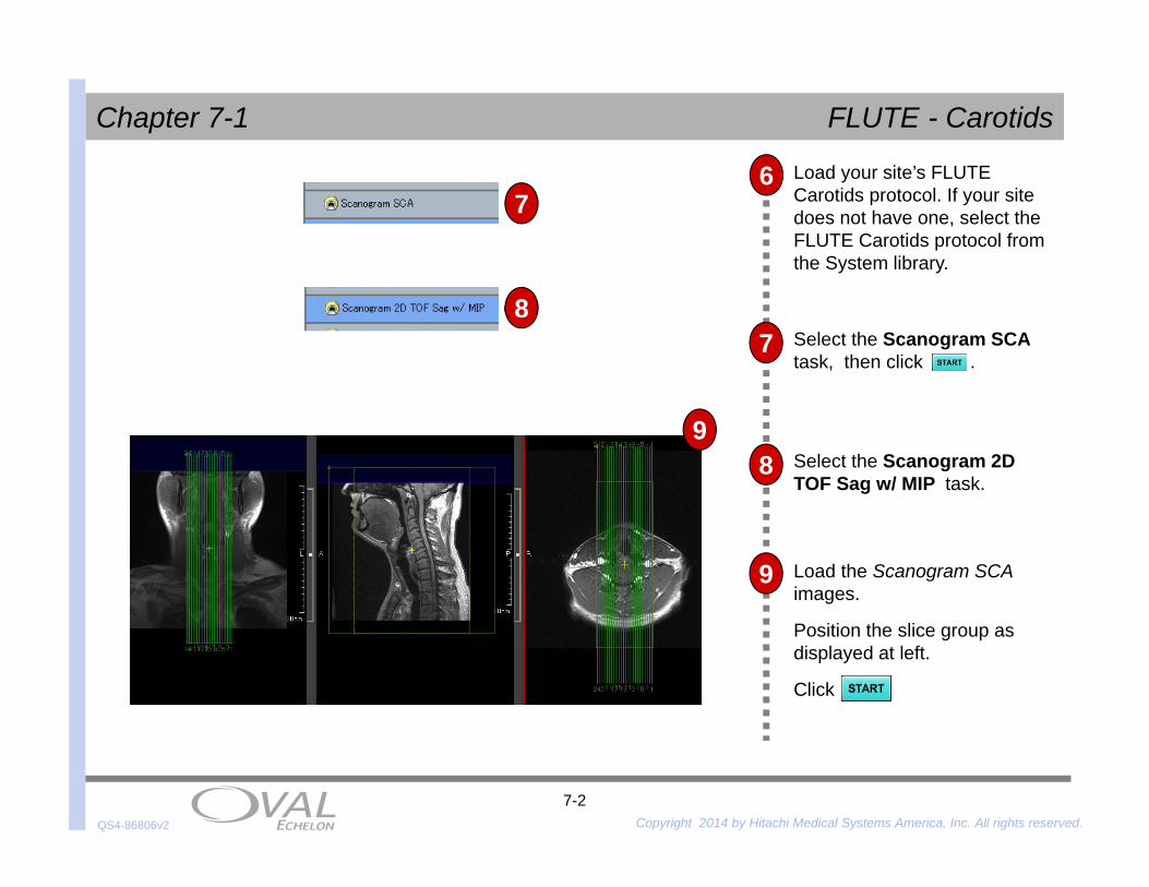
Select the Scanogram SCA task, then click .
Select the Scanogram 2D TOF Sag w/ MIP task.
7
8
7Load your site’s FLUTE Carotids protocol. If your site does not have one, select the FLUTE Carotids protocol from the System library.
8
Load the Scanogram SCA images.
Position the slice group as displayed at left.
Click
9
6
9
7
8
9
QS4-86806v2 Copyright 2014 by Hitachi Medical Systems America, Inc. All rights reserved. 7-3
Chapter 7-1 FLUTE - Carotids
Load the Scanogram SCA and Scanogram 2D TOF Sag w/ MIP images.Position the slice group as displayed, ensuring coverage of the carotid and vertebral arteries.
Select the Fluoro Scan task.Position the slice group as displayed, centering on the carotid arteries and low enough to cover the pulmonary arteries.
11
12
Select the Pre/Post FLUTE Carotids task.
10
13 Click to begin the pre-contrast (mask) scan.After completing the pre-contrast (mask) the system will pause. Ensure good image quality before continuing.
12
10
QS4-86806v2 Copyright 2014 by Hitachi Medical Systems America, Inc. All rights reserved. 7-4
Chapter 7-1 FLUTE - Carotids
Click to begin the Fluoro scan.
Shortly after the pulmonary arteries (C) are seen, the aortic arch (D) will enhance and then the carotid arteries (E).
15
17
15
Prep the power injector.
Dosage and rate will be determined by the Radiologist.
14
Fluoro Images
Subtracted Fluoro Images
A B C D E
Begin the contrast injection of the entire contrast bolus, followed by saline.
As soon as the contrast is seen in the carotid arteries, select .
HINT:
16
17
QS4-86806v2 Copyright 2014 by Hitachi Medical Systems America, Inc. All rights reserved. 7-5
Chapter 7-1 FLUTE - Carotids
18
19
20
In the Acquisition No. box, enter or select 2. In the Acquisition Scope list, click Current.
Perform MIP functions.
Select the MIP task.Load the FLUTE Carotid images into the MIP task.
Refer to Chapter 5, Post Processing, for MIP steps.
18
19
QS4-86806v2 Copyright 2014 by Hitachi Medical Systems America, Inc. All rights reserved. 7-6
Chapter 7-2 FLUTE - Renals
1
2
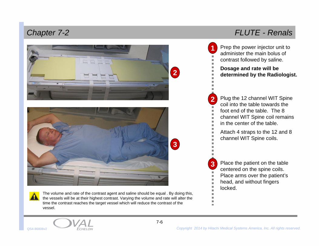
Prep the power injector unit to administer the main bolus of contrast followed by saline.Dosage and rate will be determined by the Radiologist.
3
The volume and rate of the contrast agent and saline should be equal . By doing this, the vessels will be at their highest contrast. Varying the volume and rate will alter the time the contrast reaches the target vessel which will reduce the contrast of the vessel.
4 Place the patient on the table centered on the spine coils. Place arms over the patient’s head, and without fingers locked.
Plug the 12 channel WIT Spine coil into the table towards the foot end of the table. The 8 channel WIT Spine coil remains in the center of the table. Attach 4 straps to the 12 and 8 channel WIT Spine coils.
3
2
QS4-86806v2 Copyright 2014 by Hitachi Medical Systems America, Inc. All rights reserved. 7-7
Chapter 7-2 FLUTE - Renals
Align the laser to the center of the Torso coil.
Press and hold the SET button to advance the patient to isocenter.
Place the Torso pad over the patient’s abdomen.
CautionAvoid loops in the cable. Place any excess cable between the patient table andthe pads. Prevent the cable from touching the patient or any part of themagnet bore.
Place the Torso coil over the patient’s abdomen. Use the system straps to secure the coil with the spine coils.
4
5
6
7
4
5
6
QS4-86806v2 Copyright 2014 by Hitachi Medical Systems America, Inc. All rights reserved. 7-8
Chapter 7-2 FLUTE - Renals
8
9
Load your site’s FLUTE Renals protocol. If your site does not have one, select the FLUTE Renals protocol from the System library.
Select the Scanogram SCA BH task, then click .
It is recommended that all sequences in this protocol be performed using breath-holding techniques.
10 Select the Shim Axial BH task.Load the Scanogram SCA images.Confirm the kidneys are in the center of the slice group. If necessary, reposition the patient and acquire new Scanograms.Select the button.
9
10
QS4-86806v2 Copyright 2014 by Hitachi Medical Systems America, Inc. All rights reserved. 7-9
Chapter 7-2 FLUTE - Renals
Select the Cor BASG BH task.Load the Scanogram SCA images.Position the slice group as displayed at left.Click .
11
12
Select the S-Map BH task.Load the Scanogram SCA images.Position the slice group centered to the body, as displayed at left.Select the button.
11
12
QS4-86806v2 Copyright 2014 by Hitachi Medical Systems America, Inc. All rights reserved. 7-10
Chapter 7-2 FLUTE - Renals
Select the Axial BASG BH task.
Load the Scanogram SCA images.
Position the slice group as displayed at left.Click .
14 Select the Scanogram 2D TOF Sag w/ MIP task.
Load the Scanogram SCA images.
Position the slice group as displayed at left.
Click .
13
14
13
QS4-86806v2 Copyright 2014 by Hitachi Medical Systems America, Inc. All rights reserved. 7-11
Chapter 7-2 FLUTE - Renals
Load the Cor BASG, Axial BASG and MIP image from the Scanogram 2D TOF Sag w/ MIPscan. Position the slice group as displayed at left, ensuring coverage of the anterior aorta and at least half of the kidneys.
Select the Fluoro Scan task.Position the slice group as displayed, centering on the aorta.
16
17
Select the Pre/Post FLUTE Renals BH task.
15
18 Click to begin the pre-contrast (mask) scan.After completing the pre-contrast (mask), the system will pause. Review images in the previw window to ensure good image quality before continuing.
17
15
QS4-86806v2 Copyright 2014 by Hitachi Medical Systems America, Inc. All rights reserved. 7-12
Chapter 7-2 FLUTE - Renals
Click to begin the Fluoro Scan task.
Do not breath-hold the Fluoro Scan task.
Live images will be generated in the Fluoro viewports.
20
21
20
Prep the power injector.
Dosage and rate will be determined by your radiologist.
19
Fluoro Images
Subtracted Fluoro Images
Begin the contrast injection of the entire contrast bolus, followed by saline.
As soon as the contrast is seen in the descending aorta, click .
Note: After clicking ,there will be a three to five second pause when using Auto Voice. The amount of time depends on the Auto Voice settings.
21
QS4-86806v2 Copyright 2014 by Hitachi Medical Systems America, Inc. All rights reserved. 7-13
Chapter 7-2 FLUTE - Renals
22
23
24
In the Acquisition No. Box, enter or select 2. In the Acquisition Scope list, click Current.
Perform MIP functions.
Select the MIP task.
Load the FLUTE Renals images into the MIP task.
Refer to Chapter 5, Post Processing, for MIP steps.
22
23
QS4-86806v2 Copyright 2014 by Hitachi Medical Systems America, Inc. All rights reserved. 7-14
Chapter 7-3 TRAQ - Renals
Prep the power injector unit to administer the main bolus of contrast followed by saline.Dosage and rate will be determined by the Radiologist.
The volume and rate of the contrast agent and saline should be equal . By doing this, the vessels will be at their highest contrast. Varying the volume and rate will alter the time the contrast reaches the target vessel which will reduce the contrast of the vessel.
4 Place the patient on the table centered on the spine coils. Place arms over the patient’s head, and without fingers locked.
Plug the 12 channel WIT Spine coil into the table towards the foot end of the table. The 8 channel WIT Spine coil remains in the center of the table. Attach 4 straps to the 12 and 8 channel WIT Spine coils.
1
2
3
3
2
QS4-86806v2 Copyright 2014 by Hitachi Medical Systems America, Inc. All rights reserved. 7-15
Chapter 7-3 TRAQ - Renals
CautionAvoid loops in the cable. Place any excess cable between the patient table andthe pads. Prevent the cable from touching the patient or any part of themagnet bore.
4
5
6
Align the laser to the center of the Torso coil.
Press and hold the SET button to advance the patient to isocenter.
Place the Torso pad over the patient’s abdomen.
Place the Torso coil over the patient’s abdomen. Use the system straps to secure the coil with the spine coils.
4
5
6
7
QS4-86806v2 Copyright 2014 by Hitachi Medical Systems America, Inc. All rights reserved. 7-16
Chapter 7-3 TRAQ - Renals
8
9
Load your site’s TRAQ Renals protocol. If your site does not have one, select the TRAQ Renals protocol from the System library.
Select the Scanogram SCA BH task, then click .
It is recommended that all sequences in this protocol be performed using breath-holding techniques.
10 Select the Shim Axial BH task.Load the Scanogram SCA images.Confirm the kidneys are in the center of the slice group. If necessary, reposition the patient and acquire new Scanograms.Select the button.
9
10
QS4-86806v2 Copyright 2014 by Hitachi Medical Systems America, Inc. All rights reserved. 7-17
Chapter 7-3 TRAQ - Renals
Select the Cor BASG BH task.Load the Scanogram SCA images.Position the slice group as displayed at left.Click .
11
12
Select the S-Map BH task.Load the Scanogram SCA images.Position the slice group centered to the body, as displayed at left.Select the button.
11
12
QS4-86806v2 Copyright 2014 by Hitachi Medical Systems America, Inc. All rights reserved. 7-18
Chapter 7-3 TRAQ - Renals
Select the Axial BASG BH task.
Load the Scanogram SCAimages.
Position the slice group as displayed at left.Click .
14 Select the Scanogram 2D TOF Sag w/ MIP task.
Load the Scanogram SCA images.
Position the slice group as displayed at left.
Click .
13
14
13
QS4-86806v2 Copyright 2014 by Hitachi Medical Systems America, Inc. All rights reserved. 7-19
Chapter 7-3 TRAQ - RenalsSelect the TRAQ Renal task.
17
18
16
15
Prep the power injector unit to administer the main bolus of contrast followed saline. Dosage and rate will be determined by the radiologist.
Click and wait for the prescan to complete. The continue button will appear.
Click and the INJECT button on the power injector at the SAMEtime.
The patient should be instructed to hold their breath as long as possible.
Load the Cor BASG, Axial BASG and MIP image from the Scanogram 2D TOF Sag w/ MIPscan. Position the slice group as displayed at left, ensuring coverage of the anterior aorta and at least half of the kidneys.
15
QS4-86806v2 Copyright 2014 by Hitachi Medical Systems America, Inc. All rights reserved. 7-20
Chapter 7-3 TRAQ - Renals
19
20
21
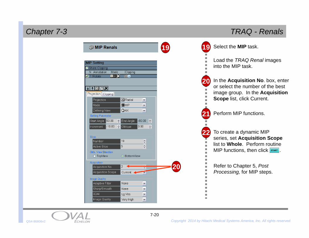
In the Acquisition No. box, enter or select the number of the best image group. In the Acquisition Scope list, click Current.
Perform MIP functions.
Select the MIP task.
Load the TRAQ Renal images into the MIP task.
To create a dynamic MIP series, set Acquisition Scopelist to Whole. Perform routine MIP functions, then click .
22
Refer to Chapter 5, Post Processing, for MIP steps.
19
20
QS4-86806v2 Copyright 2014 by Hitachi Medical Systems America, Inc. All rights reserved. 7-21
Chapter 7-4 Timed Bolus - Renals
The volume and rate of the contrast agent and saline should be equal . By doing this, the vessels will be at their highest contrast. Varying the volume and rate will alter the time the contrast reaches the target vessel which will reduce the contrast of the vessel.
4
1
2
Prep the power injector unit to administer the main bolus of contrast followed by saline.Dosage and rate will be determined by the Radiologist.
3 Place the patient on the table centered on the spine coils. Place arms over the patient’s head, and without fingers locked.
Plug the 12 channel WIT Spine coil into the table towards the foot end of the table. The 8 channel WIT Spine coil remains in the center of the table. Attach 4 straps to the 12 and 8 channel WIT Spine coils.
3
2
QS4-86806v2 Copyright 2014 by Hitachi Medical Systems America, Inc. All rights reserved. 7-22
Chapter 7-4 Timed Bolus - Renals
CautionAvoid loops in the cable. Place any excess cable between the patient table andthe pads. Prevent the cable from touching the patient or any part of themagnet bore.
4
5
6
Align the laser to the center of the Torso coil.
Press and hold the SET button to advance the patient to isocenter.
Place the Torso pad over the patient’s abdomen.
Place the Torso coil over the patient’s abdomen. Use the system straps to secure the coil with the spine coils.
4
5
6
7
QS4-86806v2 Copyright 2014 by Hitachi Medical Systems America, Inc. All rights reserved. 7-23
Chapter 7-4 Timed Bolus - Renals
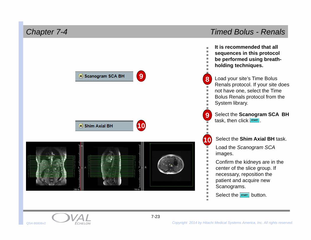
Load your site’s Time Bolus Renals protocol. If your site does not have one, select the Time Bolus Renals protocol from the System library.
Select the Scanogram SCA BH task, then click .
It is recommended that all sequences in this protocol be performed using breath-holding techniques.
Select the Shim Axial BH task.Load the Scanogram SCA images.Confirm the kidneys are in the center of the slice group. If necessary, reposition the patient and acquire new Scanograms.Select the button.
8
9
10
9
10
QS4-86806v2 Copyright 2014 by Hitachi Medical Systems America, Inc. All rights reserved. 7-24
Chapter 7-4 Timed Bolus - Renals
Select the Cor BASG BH task.Load the Scanogram SCA images.Position the slice group as displayed at left.Click .
12
13
Select the S-Map BH task.Load the Scanogram SCA images.Position the slice group centered to the body, as displayed at left.Select the button.
12
13
QS4-86806v2 Copyright 2014 by Hitachi Medical Systems America, Inc. All rights reserved. 7-25
Chapter 7-4 Timed Bolus - Renals
Select the Axial BASG BH task.
Load the Scanogram SCA images.
Position the slice group as displayed at left.Click .
15 Select the Scanogram 2D TOF Sag w/ MIP task.
Load the Scanogram SCA images.
Position the slice group as displayed at left.
Click .
14
15
14
QS4-86806v2 Copyright 2014 by Hitachi Medical Systems America, Inc. All rights reserved. 7-26
Chapter 7-4 Timed Bolus - Renals
Load the Cor BASG, Axial BASG and MIP image from the Scanogram 2D TOF Sag w/ MIP scan. Position the slice group as displayed at left, between the renal arteries and the aortic bifurcation.
Click . The system will perform a prescan, then the system will pause and the button will change to .
Select the Test Injection task.16
19 Prep the power injector unit to administer the predetermined amount of contrast and saline by the radiologist. This test injection rate should be the same as the main bolus rate from Step 1.
20
The Aorta will appear dark at first, then will become bright as contrast passes through it. Once the aorta is dark again, click Abort.
Select and the inject button on the power injector at the SAMEtime. Fluoro images will be displayed in the lower-left viewport. Click after contrast has passed through the aorta.
Fluoro Images Subtracted fluoro Images
17
18
17
20
QS4-86806v2 Copyright 2014 by Hitachi Medical Systems America, Inc. All rights reserved. 7-27
Chapter 7-4 Timed Bolus - Renals
Select the Timing Graph task.Load the Test Injection images.
21
22 On the Overlays menu, point to Add ROI, then click Ellipse to add an elliptical-shaped ROI.Draw an ellipse over the aorta.Click Apply to All .
23 A graphical representation of the bolus is displayed, allowing visualization of the bolus arrival.
18
24 For additional confirmation of the bolus arrival time, point to then click Dynamic Data Table. The Dynamic Analysis Table window is displayed.
Select the highest ROI value and the corresponding Acquisition Time.
25 Add four seconds to the bolus arrival time. This is the time that will be used as the Travel Time.
21
22
23
24
QS4-86806v2 Copyright 2014 by Hitachi Medical Systems America, Inc. All rights reserved. 7-28
The use of Auto Voice is recommended when performing Breath-Hold instructions for the main scan.
28
29
Note:
In the Travel Time box, under the Scan Control area in the Scan Parameters window, enter the Travel Time from Step 19.
Load the Cor BASG, Axial BASG and MIP image from the Scanogram 2D TOF Sag w/ MIP images.Position the slice group as displayed at left, ensuring coverage of the anterior aorta and at least half of the kidneys.
27
26
Click to begin the pre-contrast scan (mask).28
2726
QS4-86806v2 Copyright 2014 by Hitachi Medical Systems America, Inc. All rights reserved. 7-29
Chapter 7-4 Timed Bolus - Renals
32
31
30
Prep the power injector unit to administer the main bolus of contrast, followed by 15cc of saline.
After the pre-contrast (mask) scan has been performed, review the images to ensure proper coverage and good image quality.
Select and the inject button on the power injector at the SAMEtime.
In both test injection and the main scan, the total volume of the contrast agent and saline as well as injection rate should be equal . By doing this, the vessels will be at their highest contrast. Varying the total volume and its injection rate will alter the time the contrast reaches the target vessel which will reduce the contrast of the vessel.
QS4-86806v2 Copyright 2014 by Hitachi Medical Systems America, Inc. All rights reserved. 7-30
Chapter 7-4 Timed Bolus - Renals
33
34
35
In the Acquisition No. Box, enter or select 2. In the Acquisition Scope list, click Current.
Perform MIP functions.
Select the MIP task.
Load the Time Bolus Renals images into the MIP task.
Refer to Chapter 5, Post Processing, for MIP steps.