IP ADDESSING SERVICES To cope with the depletion of IP addresses, several short-term solutions were developed. Two short- term solutions are private addresses and Network Address Translation (NAT). NAT enables inside network hosts to borrow a legitimate Internet IP address while accessing Internet resources. When the requested traffic returns, the legitimate IP address is repurposed and available for the next Internet request by an inside host. Using NAT, network administrators only need one or a few IP addresses for the router to provide to the hosts, instead of one unique IP address for every client joining the network. The main feature of IPv6 that is driving adoption today is the larger address space: addresses in IPv6 are 128 bits long versus 32 bits in IPv4. DHCP Operation Providing IP addresses to clients is the most fundamental task performed by a DHCP server. DHCP includes three different address allocation mechanisms to provide flexibility when assigning IP addresses: Manual Allocation: The administrator assigns a pre-allocated IP address to the client and DHCP only communicates the IP address to the device. Automatic Allocation: DHCP automatically assigns a static IP address permanently to a device, selecting it from a pool of available addresses. There is no lease and the address is permanently assigned to a device. Dynamic Allocation: DHCP automatically dynamically assigns, or leases, an IP address from a pool of addresses for a limited period of time chosen by the server, or until the client tells the DHCP server that it no longer needs the address. This section focuses on dynamic allocation. When the client boots or otherwise wants to join a network, it completes four (4) steps in obtaining a lease: 1. In the first step, the client broadcasts a 1) DHCPDISCOVER message. The DHCPDISCOVER message finds DHCP servers on the network. Because the host has no valid IP information at bootup, it uses L2 and L3 broadcast addresses to communicate with the server. 2. When the DHCP server receives a DHCDISCOVER message, it finds an available IP address to lease, creates an ARP entry consisting of the MAC address of the requesting host and the leased IP address, and transmits a binding offer with a 2) DHCPOFFER message. The DHCPOFFER message is sent as a unicast, using the L2 MAC address of the server as the source address and the L2 address of the client as the destination. Section 7 Page 1 of 62
Transcript
IP ADDESSING SERVICES
To cope with the depletion of IP addresses, several short-term solutions were developed. Two short-
term solutions are private addresses and Network Address Translation (NAT).
NAT enables inside network hosts to borrow a legitimate Internet IP address while accessing Internet
resources. When the requested traffic returns, the legitimate IP address is repurposed and available for
the next Internet request by an inside host. Using NAT, network administrators only need one or a few
IP addresses for the router to provide to the hosts, instead of one unique IP address for every client
joining the network.
The main feature of IPv6 that is driving adoption today is the larger address space: addresses in IPv6 are
128 bits long versus 32 bits in IPv4.
DHCP Operation
Providing IP addresses to clients is the most fundamental task performed by a DHCP server. DHCP
includes three different address allocation mechanisms to provide flexibility when assigning IP
addresses:
Manual Allocation: The administrator assigns a pre-allocated IP address to the client and DHCP
only communicates the IP address to the device.
Automatic Allocation: DHCP automatically assigns a static IP address permanently to a device,
selecting it from a pool of available addresses. There is no lease and the address is permanently
assigned to a device.
Dynamic Allocation: DHCP automatically dynamically assigns, or leases, an IP address from a
pool of addresses for a limited period of time chosen by the server, or until the client tells the
DHCP server that it no longer needs the address.
This section focuses on dynamic allocation. When the client boots or otherwise wants to join a network,
it completes four (4) steps in obtaining a lease:
1. In the first step, the client broadcasts a 1) DHCPDISCOVER message. The DHCPDISCOVER
message finds DHCP servers on the network. Because the host has no valid IP information at
bootup, it uses L2 and L3 broadcast addresses to communicate with the server.
2. When the DHCP server receives a DHCDISCOVER message, it finds an available IP address to
lease, creates an ARP entry consisting of the MAC address of the requesting host and the leased
IP address, and transmits a binding offer with a 2) DHCPOFFER message. The DHCPOFFER
message is sent as a unicast, using the L2 MAC address of the server as the source address and
the L2 address of the client as the destination.
Section 7 Page 1 of 62
3. When the client receives the DHCPOFFER from the server, it sends back a 3) DHCPREQUEST
message. This message has two purposes: lease origination and lease renewal and verification.
When used for lease origination, the DHCPREQUEST of the client is requesting that the IP
information be verified just after it has been assigned. The DHCPREQUEST also serves as a
binding acceptance notice to the selected server and an implicit decline to any other servers
that may have provided the host a binding offer.
4. On receiving the DHCPREQUEST message, the server verifies the lease information, creates a
new ARP entry for the client lease, and replies with a unicast 4) DHCPACK message. The
DHCPACK message is a duplicate of the DHCPOFFER, except for a change in the message type
field. When the client receives the DHCPACK message, it logs the configuration information and
performs an ARP lookup for the assigned address. If it does not receive a reply, it knows that the
IP address is valid and starts using it as its own.
BOOTP and DHCP
The Bootstrap Protocol (BOOTP), defined in RFC 951, is the predecessor of DHCP and shares some
operational characteristics. BOOTP is a way to download address and boot configurations for diskless
workstations. A diskless workstation does not have a hard drive or an operating system. For example,
many automated cash register systems at your local super market are examples of diskless workstations.
Both DHCP and BOOTP are client/server based and use UDP ports 67 and 68.
DHCP and BOOTP have two components. The server is a host with a static IP address that allocates,
distributes, and manages IP and configuration data assignments. Each allocation (IP and configuration
data) is stored on the server in a data set called a binding.
2. Establish dynamic source translation, specifying the access list defined in the prior step.
Router(config)#ip nat inside source list acl-number interface interface overload
3. Specify the inside interface.
Router(config)#interface type number
Router(config-if)#ip nat inside
4. Specify the outside interface.
Router(config-if)#interface type number
Router(config-if)#ip nat outside
Section 7 Page 12 of 62
Configuration TIPs:
Enter the global command no access-list access-list-number to remove the access list.
Enter the global command no ip nat inside source to remove the dynamic source
translation. The overload keyword enables PAT.
The configuration is similar to dynamic NAT, except that instead of a pool of addresses, the interface keyword is used to identify the outside IP address. Therefore, no NAT pool is defined. The overload keyword enables the addition of the port number to the translation.
Configuring NAT Overload for a Pool of Public IP Addresses
Steps:
1. Define a standard access list permitting those addresses that are to be translated.
2. Specify the global address, as a pool, to be used for overloading.
Router(config)#ip nat pool name start-ip end-ip {netmask netmask | prefix-length prefix-length}.
3. Establish overload translation.
Router {config}#ip nat inside source list acl-number pool name overload.
4. Specify the inside interface.
Router(config)#interface type number
Router(config-if)#ip nat inside
5. Specify the outside interface.
Router(config-if)#interface type number
Router(config-if)#ip nat outside
Port Forwarding
Port forwarding (sometimes referred to as tunneling) is the act of forwarding a network port from one network node to another. This technique can allow an external user to reach a port on a private IP address (inside a LAN) from the outside through a NAT-enabled router.
Typically, peer-to-peer file-sharing programs and key operations, such as web serving and outgoing FTP, require that router ports be forwarded or opened to allow these applications to work. Because NAT hides internal addresses, peer-to-peer only works from the inside out where NAT can map register outgoing requests against incoming replies. The problem is that NAT does not allow requests initiated from the outside. This situation can be resolved with manual intervention. Port forwarding allows you to identify specific ports that can be forwarded to inside hosts.
Configuring Port Forwarding
Port forwarding allows users on the Internet to access internal servers by using the WAN port address and the matched external port number.
Section 7 Page 13 of 62
When users send these types of requests to your WAN port IP address via the Internet, the router forwards those requests to the appropriate servers on your LAN. For security reasons, broadband routers do not by default permit any external network request to be forwarded to an inside host.
The approach you take to configure port forwarding depends on the brand and model of the broadband router in the network. However, there are some generic steps to follow. If the instructions supplied by your ISP or that came with the router do not provide adequate guidance, the website www.portforward.com provides guides for several broadband routers. You can follow the instructions to add or delete ports as required to meet the needs of any applications you want to allow or deny.
Verifying NAT and NAT Overload
It is important to verify NAT operation. There are several useful router commands to view and clear NAT translations:
1. show ip nat translations - Before using the show commands to verify NAT, you must clear any dynamic translation entries that might still be present, because by default, dynamic address translations time out from the NAT translation table after a period of non-use.
2. show ip nat translations verbose - This command displays the details of NAT assignments. Adding verbose to the command displays additional information about each translation, including how long ago the entry was created and used.
3. show ip nat statistics - This command displays information about the total number of active translations, NAT configuration parameters, how many addresses are in the pool, and how many have been allocated.
4. show run - Use this command and look for NAT, access command list, interface, or pool commands with the required values. Examine these carefully and correct any errors you discover.
5. ip nat translation timeout timeout_ second - By default, translation entries time out after 24 hours, unless the timers have been reconfigured with this command (global command).
6. To clear dynamic entries before the timeout has expired, use the clear ip nat translation global command.
Troubleshooting NAT and NAT Overload Configuration When you have IP connectivity problems in a NAT environment, it is often difficult to determine the cause of the problem. The first step in solving your problem is to rule out NAT as the cause. Follow these steps to verify that NAT is operating as expected:
Step 1. Based on the configuration, clearly define what NAT is supposed to achieve. This may reveal a problem with the configuration.
Step 2. Verify that correct translations exist in the translation table using the show ip nat translations command.
Step 3. Use the clear and debug commands to verify that NAT is operating as expected. Check to see if dynamic entries are recreated after they are cleared.
Step 4. Review in detail what is happening to the packet, and verify that routers have the correct routing information to move the packet.
Use the debug ip nat command to verify the operation of the NAT feature by displaying information about every packet that is translated by the router. The debug ip nat detailed command generates a
Section 7 Page 14 of 62
description of each packet considered for translation. This command also outputs information about certain errors or exception conditions, such as the failure to allocate a global address.
When decoding the debug output, note what the following symbols and values indicate:
* - The asterisk next to NAT indicates that the translation is occurring in the fast-switched path. The first packet in a conversation is always process-switched, which is slower. The remaining packets go through the fast-switched path if a cache entry exists.
s = - Refers to the source IP address.
a.b.c.d--->w.x.y.z - Indicates that source address a.b.c.d is translated to w.x.y.z.
d= - Refers to the destination IP address.
[xxxx] - The value in brackets is the IP identification number. This information may be useful for debugging in that it enables correlation with other packet traces from protocol analyzers.
You can view the following demonstrations about verifying and troubleshooting NAT at these sites:
Flash Animation Case Study: Can Ping Host, but Cannot Telnet: This is a seven-minute Flash animation on why a device can ping the host, but cannot telnet: http://www.cisco.com/warp/public/556/index.swf.
Flash Animation Case Study: Cannot Ping Beyond NAT: This is a ten-minute Flash animation on why a device cannot ping beyond NAT: http://www.cisco.com/ warp/public/ 556/ TS_NATcase2/Index.swf.
IPv4 will not disappear overnight. Rather, it will coexist with and then gradually be replaced by IPv6. For this reason, IPv6 was delivered with migration techniques to cover every conceivable IPv4 upgrade case. However, many were ultimately rejected by the technology community.
Note: The current advice for transitioning to IPv6 is "Dual stack where you can, tunnel where you must!"
The figure shows the address 2031:0000:130F:0000:0000:09C0:876A:130B. IPv6 does not require explicit address string notation. The figure shows how to shorten the address by applying the following guidelines:
Leading zeros in a field are optional. For example, the field 09C0 equals 9C0, and the field 0000 equals 0. So 2031:0000:130F:0000:0000:09C0:876A:130B can be written as 2031:0:130F:0000:0000:9C0:876A:130B.
Successive fields of zeros can be represented as two colons "::". However, this shorthand method can only be used once in an address. For example 2031:0:130F:0000:0000:9C0:876A:130B can be written as 2031:0:130F::9C0:876A:130B.
An unspecified address is written as "::" because it contains only zeros.
IPv6 Global Unicast Address
IPv6 has an address format that enables aggregation upward eventually to the ISP. Global unicast addresses typically consists of a 48-bit global routing prefix and a 16-bit subnet ID. Individual organizations can use a 16-bit subnet field to create their own local addressing hierarchy. This field allows an organization to use up to 65,535 individual subnets.
Note: Private addresses have a first octet value of "FE" in hexadecimal notation, with the next hexadecimal digit being a value from 8 to F.
These addresses are further divided into two types, based upon their scope:
Site-local addresses: are addresses similar to the RFC 1918 Address Allocation for Private Internets in IPv4 today. However, the use of site-local addresses is problematic and is being
Section 7 Page 16 of 62
deprecated as of 2003 by RFC 3879. In hexadecimal, site-local addresses begin with "FE" and then "C" to "F" for the third hexadecimal digit. So, these addresses begin with "FEC", "FED", "FEE", or "FEF".
Link-local addresses: are new to the concept of addressing with IP in the Network layer. These addresses have a smaller scope than site-local addresses; they refer only to a particular physical link (physical network). Routers do not forward datagrams using link-local addresses at all, not even within the organization; they are only for local communication on a particular physical network segment.
The IPv6 is broken down by bits and represents different Entities involved with a slash number similar to CIDR:
/23 = Represents the Registry, that assigned the IP Block, Prefix
/32 = The ISP Prefix
/48 = The Site Prefix
/64 = The Subnet Prefix
Loopback Address
Just as in IPv4, a provision has been made for a special loopback IPv6 address for testing; datagrams sent to this address "loop back" to the sending device. However, in IPv6 there is just one address, not a whole block, for this function. The loopback address is 0:0:0:0:0:0:0:1, which is normally expressed using zero compression as "::1".
Unspecified Address
In IPv4, an IP address of all zeroes has a special meaning; it refers to the host itself, and is used when a device does not know its own address.
IPv6 Address Management
IPv6 addresses use interface identifiers to identify interfaces on a link. Think of them as the host portion of an IPv6 address. Interface identifiers are required to be unique on a specific link. Interface identifiers are always 64 bits and can be dynamically derived from a Layer 2 address (MAC).
You can assign an IPv6 address ID statically or dynamically:
Static assignment using a manual interface ID
Static assignment using an EUI-64 interface ID
Stateless auto-configuration Dynamic
DHCP for IPv6 (DHCPv6) Dynamic
To configure an IPv6 address on a Cisco router interface, use the ipv6 address ipv6-address/prefix-length command in interface configuration mode. The following example shows the assignment of an IPv6 address to the interface of a Cisco router:
Another way to assign an IPv6 address is to configure the prefix (network) portion of the IPv6 address
Section 7 Page 17 of 62
and derive the interface ID (host) portion from the Layer 2 MAC address of the device, which is known as the EUI-64 interface ID.
DHCPv6 (Stateful)
DHCPv6 enables DHCP servers to pass configuration parameters, such as IPv6 network addresses, to IPv6 nodes. It offers the capability of automatic allocation of reusable network addresses and additional configuration flexibility.
IPv6 Transition Strategies
The transition from IPv4 does not require upgrades on all nodes at the same time. Many transition mechanisms enable smooth integration of IPv4 and IPv6.
Recall the advice: "Dual stack where you can, tunnel where you must." These two methods are the most common techniques to transition from IPv4 to IPv6.
Dual Stacking
Dual stacking is an integration method in which a node has implementation and connectivity to both an IPv4 and IPv6 network. This is the recommended option and involves running IPv4 and IPv6 at the same time. Router and switches are configured to support both protocols, with IPv6 being the preferred protocol.
Tunneling
The second major transition technique is tunneling. There are several tunneling techniques available, including:
Manual IPv6-over-IPv4 tunneling - An IPv6 packet is encapsulated within the IPv4 protocol. This method requires dual-stack routers.
Dynamic 6to4 tunneling - Automatically establishes the connection of IPv6 islands through an IPv4 network, typically the Internet. It dynamically applies a valid, unique IPv6 prefix to each IPv6 island, which enables the fast deployment of IPv6 in a corporate network without address retrieval from the ISPs or registries.
NAT-Protocol Translation (NAT-PT)
Cisco IOS Release 12.3(2)T and later (with the appropriate feature set) also include NAT-PT between IPv6 and IPv4. This translation allows direct communication between hosts that use different versions of the IP protocol. These translations are more complex than IPv4 NAT. At this time, this translation technique is the least favorable option and should be used as a last resort.
Cisco IOS Dual Stack
Dual stacking is an integration method that allows a node to have connectivity to an IPv4 and IPv6 network simultaneously. Each node has two protocol stacks with the configuration on the same interface or on multiple interfaces.
A new application programming interface (API) has been defined to support IPv4 and IPv6 addresses and DNS requests. An API facilitates the exchange of messages or data between two or more different software applications. An example of an API is the virtual interface between two software functions,
Section 7 Page 18 of 62
such as a word processor and a spreadsheet. The API is built into software applications to translate IPv4 into IPv6, and vice versa using the IP conversion mechanism. New applications can use both IPv4 and IPv6.
Cisco IOS Release 12.2(2)T and later (with the appropriate feature set) are IPv6-ready. As soon as you configure basic IPv4 and IPv6 on the interface, the interface is dual-stacked and forwards IPv4 and IPv6 traffic on that interface. Note that an IPv4 and an IPv6 address have been configured.
Using IPv6 on a Cisco IOS router requires that you use the global configuration command ipv6 unicast-routing. This command enables the forwarding of IPv6 datagrams.
You must configure all interfaces that forward IPv6 traffic with an IPv6 address using the ipv6 addressIPv6-address [/prefix length] interface command.
IPv6 Tunneling
Tunneling is an integration method where an IPv6 packet is encapsulated within another protocol, such as IPv4. This method enables the connection of IPv6 islands without needing to convert the intermediary networks to IPv6. When IPv4 is used to encapsulate the IPv6 packet, a protocol type of 41 is specified in the IPv4 header, and the packet includes a 20-byte IPv4 header with no options and an IPv6 header and payload. It also requires dual-stack routers.
Tunneling presents these two issues.
The maximum transmission unit (MTU) is effectively decreased by 20 octets if the IPv4 header does not contain any optional fields.
In addition, a tunneled network is often difficult to troubleshoot.
Note: Tunneling is an intermediate integration and transition technique and should not be considered as a final solution. A native IPv6 architecture should be the ultimate goal.
Manually Configured IPv6 Tunnel
Administrators manually configure a static IPv6 address on a tunnel interface, and assign manually configured static IPv4 addresses to the tunnel source and the tunnel destination. The host or router at each end of a configured tunnel must support both the IPv4 and IPv6 protocol stacks. Manually configured tunnels can be configured between border routers or between a border router and a host.
Routing Configurations with IPv6
Like IPv4 classless interdomain routing (CIDR), IPv6 uses longest prefix match routing. IPv6 uses modified versions of most of the common routing protocols to handle longer IPv6 addresses and different header structures.
A brief review of how a router functions in a network helps illustrate how IPv6 affects routing. Conceptually, a router has three functional areas:
The control plane handles the interaction of the router with the other network elements, providing the information needed to make decisions and control the overall router operation.
Section 7 Page 19 of 62
This plane runs processes such as routing protocols and network management. These functions are generally complex.
The data plane handles packet forwarding from one physical or logical interface to another. It involves different switching mechanisms such as process switching and Cisco Express Forwarding (CEF) on Cisco IOS software routers.
Enhanced services include advanced features applied when forwarding data, such as packet filtering, quality of service (QoS), encryption, translation, and accounting.
IPv6 Control Plane
Enabling IPv6 on a router starts its CONTROL PLANE operating processes specifically for IPv6. Protocol characteristics shape the performance of these processes and the amount of resources necessary to operate them:
IPv6 address size - Address size affects the information-processing functions of a router. Systems using a 64-bit CPU, bus, or memory structure can pass both the IPv4 source and destination address in a single processing cycle. For IPv6, the source and destination addresses require two cycles each-four cycles to process source and destination address information. As a result, routers relying exclusively on software processing are likely to perform slower than when in an IPv4 environment.
Multiple IPv6 node addresses - Because IPv6 nodes can use several IPv6 unicast addresses, memory consumption of the Neighbor Discovery cache may be affected.
IPv6 routing protocols - IPv6 routing protocols are similar to their IPv4 counterparts, but since an IPv6 prefix is four times larger than an IPv4 prefix, routing updates have to carry more information.
Routing table Size -Increased IPv6 address space leads to larger networks and a much larger Internet. This implies larger routing tables and higher memory requirements to support them.
IPv6 Data Plane
The DATA PLANE forwards IP packets based on the decisions made by the control plane. The forwarding engine parses the relevant IP packet information and does a lookup to match the parsed information against the forwarding policies defined by the control plane. IPv6 affects the performance of parsing and lookup functions:
Parsing IPv6 extension headers - Applications, including mobile IPv6, often use IPv6 address information in extension headers, thus increasing their size. These additional fields require additional processing. For example, a router using ACLs to filter Layer 4 information needs to apply the ACLs to packets with extension headers as well as those without. If the length of the extension header exceeds the fixed length of the hardware register of the router, hardware switching fails, and packets may be punted to software switching or dropped. This severely affects the forwarding performance of the router.
IPv6 address lookup - IPv6 performs a lookup on packets entering the router to find the correct output interface. In IPv4, the forwarding decision process parses a 32-bit destination address. In IPv6, the forwarding decision could conceivably require parsing a 128-bit address. Most routers today perform lookups using an application-specific integrated circuit (ASIC) with a fixed configuration that performs the functions for which it was originally designed - IPv4. Again, this could result in punting packets into slower software processing, or dropping them all together.
Section 7 Page 20 of 62
RIPNg Routing Protocol IPv6 routes use the same protocols and techniques as IPv4. Although the addresses are longer, the protocols used in routing IPv6 are simply logical extensions of the protocols used in IPv4. RFC 2080 defines Routing Information Protocol next generation (RIPng) as a simple routing protocol based on RIP. RIPng is no more or less powerful than RIP, however, it provides a simple way to bring up an IPv6 network without having to build a new routing protocol. RIPng is a distance vector routing protocol with a limit of 15 hops that uses split horizon and poison reverse updates to prevent routing loops. Its simplicity comes from the fact that it does not require any global knowledge of the network. Only neighboring routers exchange local messages. RIPng includes the following features:
Based on IPv4 RIP version 2 (RIPv2) and is similar to RIPv2
Uses IPv6 for transport
Includes the IPv6 prefix and next-hop IPv6 address
Uses the multicast group FF02::9 as the destination address for RIP updates (this is similar to the broadcast function performed by RIP in IPv4)
Sends updates on UDP port 521
Is supported by Cisco IOS Release 12.2(2)T and later
Note: In dual-stacked deployments, both RIP and RIPng are required.
Enabling IPv6 on Cisco Routers
To activate it between interfaces, you must configure the global command ipv6 unicast-routing.
The ipv6 address command can configure a global IPv6 address. The link-local address is automatically configured when an address is assigned to the interface. You must specify the entire 128-bit IPv6 address or specify to use the 64-bit prefix by using the eui-64 option.
RouterX(config)#ipv6 unicast-routing - Enables IPv6 on Cisco Routers RouterX(config-if)#ipv6 address ipv6prefix/prefix-length eui-64 - Configures the interface IPv6
addresses
Note: You can completely specify the IPv6 address or compute the host identifier (rightmost 64 bits) from the EUI-64 identifier of the interface.
Configure RIPng with IPv6
When configuring supported routing protocols in IPv6, you must create the routing process, enable the routing process on interfaces, and customize the routing protocol for your particular network.
To enable RIPng routing on the router, use the ipv6 router rip name global configuration command. The name parameter identifies the RIP process. This process name is used later when configuring RIPng on participating interfaces.
Section 7 Page 21 of 62
For RIPng, instead of using the network command to identify which interfaces should run RIPng, you use the command ipv6 rip name enable in interface configuration mode to enable RIPng on an interface. The name parameter must match the name parameter in the ipv6 router rip comman
Cisco IOS IPv6 Name Resolution
There are two ways to perform name resolution from the Cisco IOS software process:
1. Define a static name for an IPv6 address using the ipv6 host name [port] ipv6-address1 [ipv6-address2...ipv6-address4] command. You can define up to four IPv6 addresses for one hostname. The port option refers to the Telnet port to be used for the associated host. Configuration Commands:
RouterX(config)#ipv6 host name [port] ipv6addr [{ipv6addr} ...] - Define a static name for IPv6 addresses
RouterX(config)#ipv6 host router1 3ffe:b00:ffff:b::1 - Define a static name for IPv6
2. Specify the DNS server used by the router with the ip name-server address command. The address can be an IPv4 or IPv6 address. You can specify up to six DNS servers with this command. Configuration Commands:
RouterX(config)#ip name-server address - Configure a DNS server or servers to query
RouterX(config)#ip name-server 3ffe:b00:ffff:1::10 - Configure a DNS server or servers to query
In this lab, you will configure the DHCP and NAT IP services. One router is the DHCP server. The other router forwards DHCP requests to the server. You will also configure both static and dynamic NAT configurations, including NAT overload. When you have completed the configurations, verify the connectivity between the inside and outside addresses.
Task 1: Prepare the Network
Step 1: Cable a network that is similar to the one in the topology diagram.
You can use any current router in your lab as long as it has the required interfaces shown in the topology.
Note: If you use a 1700, 2500, or 2600 series router, the router outputs and interface descriptions may look different. On older routers some commands may be different, or not exist.
Step 2: Clear all existing configurations on the routers.
Task 2: Perform Basic Router Configurations
Configure the R1, R2, and ISP routers according to the following guidelines:
Configure the device hostname.
Disable DNS lookup.
Configure a privileged EXEC mode password.
Configure a message-of-the-day banner.
Configure a password for the console connections.
Configure a password for all vty connections.
Configure IP addresses on all routers. The PCs receive IP addressing from DHCP later in the lab.
Enable OSPF with process ID 1 on R1 and R2. Do not advertise the 209.165.200.224/27 network.
Note: Instead of attaching a server to R2, you can configure a loopback interface on R2 to use the IP address 192.168.20.254/24. If you do this, you do not need to configure the Fast Ethernet interface.
Task 3: Configure PC1 and PC2 to receive an IP address through DHCP
On a Windows PC go to Start -> Control Panel -> Network Connections -> Local Area Connection. Right mouse click on the Local Area Connection and select Properties.
Section 7 Page 24 of 62
CCNA Exploration Accessing the WAN: IP Addressing Services Lab 7.4.1: Basic DHCP and NAT Configuration
Once this has been done on both PC1 and PC2, they are ready to receive an IP address from a DHCP server.
Task 4: Configure a Cisco IOS DHCP Server
Cisco IOS software supports a DHCP server configuration called Easy IP. The goal for this lab is to have devices on the networks 192.168.10.0/24 and 192.168.11.0/24 request IP addresses via DHCP from R2.
Step 1: Exclude statically assigned addresses.
The DHCP server assumes that all IP addresses in a DHCP address pool subnet are available for assigning to DHCP clients. You must specify the IP addresses that the DHCP server should not assign to clients. These IP addresses are usually static addresses reserved for the router interface, switch management IP address, servers, and local network printer. The ip dhcp excluded-address command prevents the router from assigning IP addresses within the configured range. The following commands exclude the first 10 IP addresses from each pool for the LANs attached to R1. These addresses will not be assigned to any DHCP clients.
Create the DHCP pool using the ip dhcp pool command and name it R1Fa0.
R2(config)#ip dhcp pool R1Fa0
Specify the subnet to use when assigning IP addresses. DHCP pools automatically associate with an interface based on the network statement. The router now acts as a DHCP server, handing out addresses in the 192.168.10.0/24 subnet starting with 192.168.10.1.
Configure the default router and domain name server for the network. Clients receive these settings via DHCP, along with an IP address.
R2(dhcp-config)#dns-server 192.168.11.5
R2(dhcp-config)#default-router 192.168.10.1
Note: There is not a DNS server at 192.168.11.5. You are configuring the command for practice only.
Because devices from the network 192.168.11.0/24 also request addresses from R2, a separate pool must be created to serve devices on that network. The commands are similar to the commands shown above:
Why are these the results? These are the results because DHCP requests are not routable and therefore they aren’t sent to the router R2.
Step 4: Configure a helper address.
Network services such as DHCP rely on Layer 2 broadcasts to function. When the devices providing these services exist on a different subnet than the clients, they cannot receive the broadcast packets. Because the DHCP server and the DHCP clients are not on the same subnet, configure R1 to forward DHCP broadcasts to R2, which is the DHCP server, using the ip helper-address interface configuration command.
Notice that ip helper-address must be configured on each interface involved.
R1(config)#interface fa0/0
R1(config-if)#ip helper-address 10.1.1.2
R1(config)#interface fa0/1
R1(config-if)#ip helper-address 10.1.1.2
Step 5: Release and Renew the IP addresses on PC1 and PC2
Depending upon whether your PCs have been used in a different lab, or connected to the internet, they may already have learned an IP address automatically from a different DHCP server. We need to clear this IP address using the ipconfig /release and ipconfig /renew commands.
Step 6: Verify the DHCP configuration.
You can verify the DHCP server configuration in several different ways. Issue the command ipconfig on PC1 and PC2 to verify that they have now received an IP address dynamically. You can then issue commands on the router to get more information. The show ip dhcp binding command provides information on all currently assigned DHCP addresses. For instance, the following output shows that the IP address 192.168.10.11 has been assigned to MAC address 3031.632e.3537.6563. The IP lease expires on September 14, 2007 at 7:33 p.m.
The show ip dhcp pool command displays information on all currently configured DHCP pools on the router. In this output, the pool R1Fa0 is configured on R1. One address has been leased from this pool. The next client to request an address will receive 192.168.10.12.
R2#show ip dhcp pool
Pool R1Fa0 :
Utilization mark (high/low) : 100 / 0
Subnet size (first/next) : 0 / 0
Total addresses : 254
Leased addresses : 1
Pending event : none
1 subnet is currently in the pool :
Current index IP address range Leased addresses
192.168.10.12 192.168.10.1 - 192.168.10.254 1
The debug ip dhcp server events command can be extremely useful when troubleshooting DHCP leases with a Cisco IOS DHCP server. The following is the debug output on R1 after connecting a host. Notice that the highlighted portion shows DHCP giving the client an address of 192.168.10.12 and mask of 255.255.255.0
*Sep 13 21:04:18.072: DHCPD: Sending notification of DISCOVER:
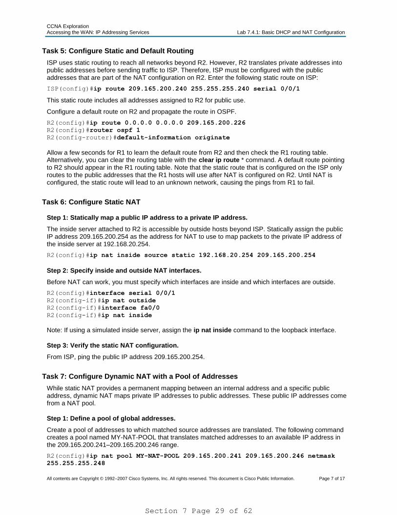
ISP uses static routing to reach all networks beyond R2. However, R2 translates private addresses into public addresses before sending traffic to ISP. Therefore, ISP must be configured with the public addresses that are part of the NAT configuration on R2. Enter the following static route on ISP:
ISP(config)#ip route 209.165.200.240 255.255.255.240 serial 0/0/1
This static route includes all addresses assigned to R2 for public use.
Configure a default route on R2 and propagate the route in OSPF.
Allow a few seconds for R1 to learn the default route from R2 and then check the R1 routing table. Alternatively, you can clear the routing table with the clear ip route * command. A default route pointing to R2 should appear in the R1 routing table. Note that the static route that is configured on the ISP only routes to the public addresses that the R1 hosts will use after NAT is configured on R2. Until NAT is configured, the static route will lead to an unknown network, causing the pings from R1 to fail.
Task 6: Configure Static NAT
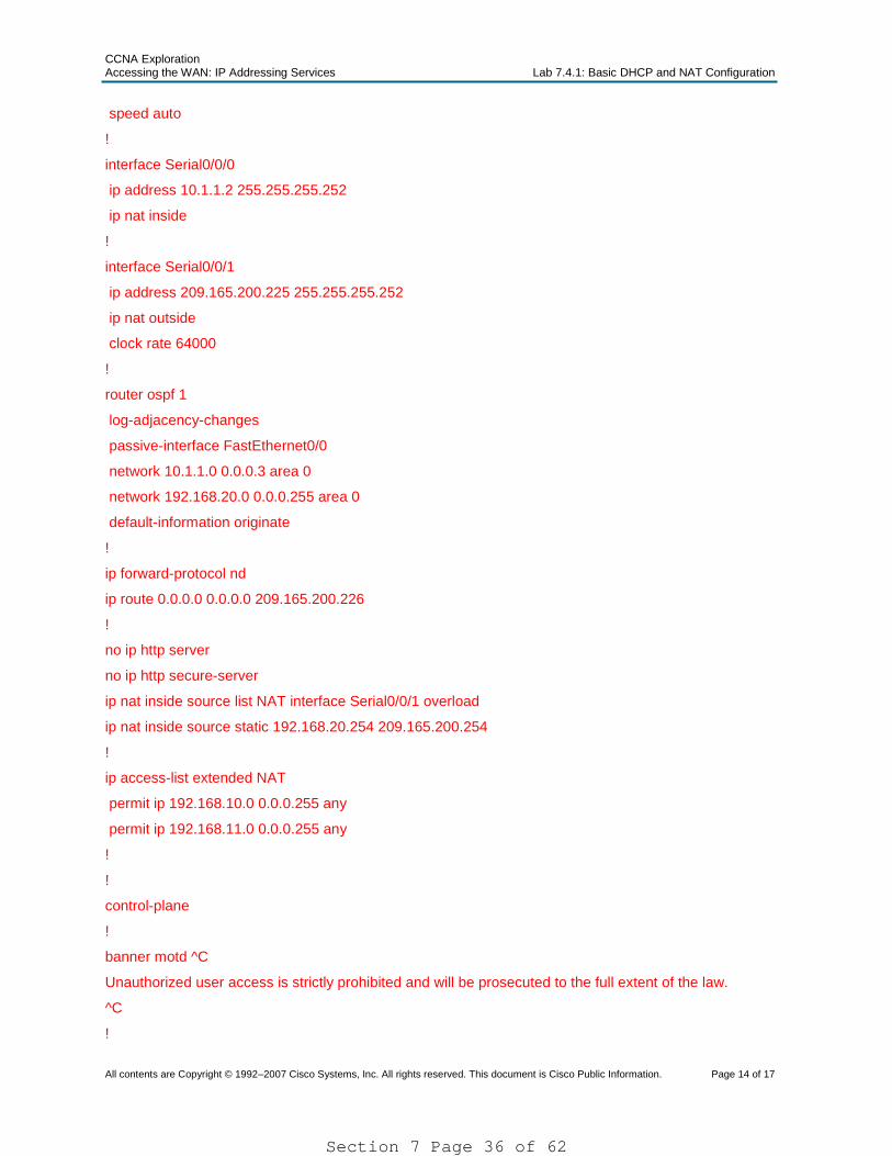
Step 1: Statically map a public IP address to a private IP address.
The inside server attached to R2 is accessible by outside hosts beyond ISP. Statically assign the public IP address 209.165.200.254 as the address for NAT to use to map packets to the private IP address of the inside server at 192.168.20.254.
Step 2: Specify inside and outside NAT interfaces.
Before NAT can work, you must specify which interfaces are inside and which interfaces are outside.
R2(config)#interface serial 0/0/1
R2(config-if)#ip nat outside
R2(config-if)#interface fa0/0
R2(config-if)#ip nat inside
Note: If using a simulated inside server, assign the ip nat inside command to the loopback interface.
Step 3: Verify the static NAT configuration.
From ISP, ping the public IP address 209.165.200.254.
Task 7: Configure Dynamic NAT with a Pool of Addresses
While static NAT provides a permanent mapping between an internal address and a specific public address, dynamic NAT maps private IP addresses to public addresses. These public IP addresses come from a NAT pool.
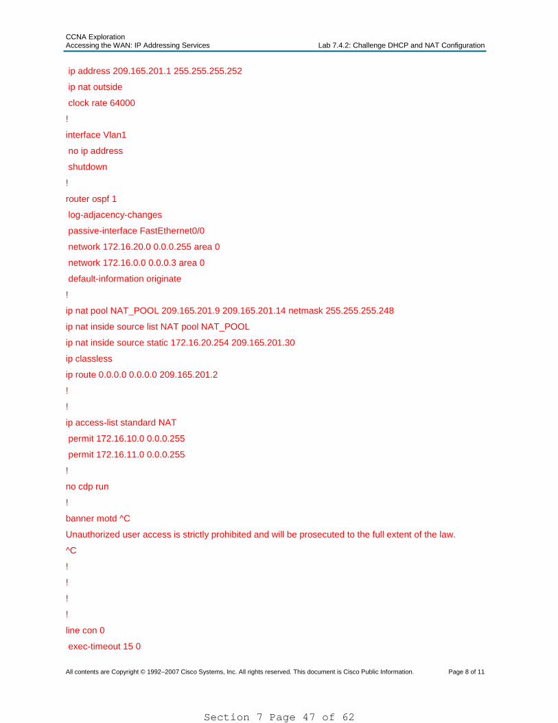
Step 1: Define a pool of global addresses.
Create a pool of addresses to which matched source addresses are translated. The following command creates a pool named MY-NAT-POOL that translates matched addresses to an available IP address in the 209.165.200.241–209.165.200.246 range.
R2(config)#ip nat pool MY-NAT-POOL 209.165.200.241 209.165.200.246 netmask
255.255.255.248
Section 7 Page 29 of 62
CCNA Exploration Accessing the WAN: IP Addressing Services Lab 7.4.1: Basic DHCP and NAT Configuration
Step 2: Create an extended access control list to identify which inside addresses are translated.
R2(config)#ip access-list extended NAT
R2(config-ext-nacl)#permit ip 192.168.10.0 0.0.0.255 any
R2(config-ext-nacl)#permit ip 192.168.11.0 0.0.0.255 any
Step 3: Establish dynamic source translation by binding the pool with the access control list.
A router can have more than one NAT pool and more than one ACL. The following command tells the router which address pool to use to translate hosts that are allowed by the ACL.
R2(config)#ip nat inside source list NAT pool MY-NAT-POOL
Step 4: Specify inside and outside NAT interfaces.
You have already specified the inside and outside interfaces for your static NAT configuration. Now add the serial interface linked to R1 as an inside interface.
R2(config)#interface serial 0/0/0
R2(config-if)#ip nat inside
Step 5: Verify the configuration.
Ping ISP from PC1 or the Fast Ethernet interface on R1 using extended ping. Then use the show ip nat translations and show ip nat statistics commands on R2 to verify NAT.
R2#show ip nat translations
Pro Inside global Inside local Outside local Outside global
In the previous example, what would happen if you needed more than the six public IP addresses that the pool allows?
Then one of the packets would have been dropped.
By tracking port numbers, NAT overloading allows multiple inside users to reuse a public IP address.
In this task, you will remove the pool and mapping statement configured in the previous task. Then you will configure NAT overload on R2 so that all internal IP addresses are translated to the R2 S0/0/1 address when connecting to any outside device.
Step 1: Remove the NAT pool and mapping statement.
Use the following commands to remove the NAT pool and the map to the NAT ACL.
R2(config)#no ip nat inside source list NAT pool MY-NAT-POOL
R2(config)#no ip nat pool MY-NAT-POOL 209.165.200.241 209.165.200.246 netmask
255.255.255.248
If you receive the following message, clear your NAT translations.
%Pool MY-NAT-POOL in use, cannot destroy
R2#clear ip nat translation *
Step 2: Configure PAT on R2 using the serial 0/0/1 interface public IP address.
The configuration is similar to dynamic NAT, except that instead of a pool of addresses, the interface keyword is used to identify the outside IP address. Therefore, no NAT pool is defined. The overload keyword enables the addition of the port number to the translation.
Because you already configured an ACL to identify which inside IP addresses to translate as well as which interfaces are inside and outside, you only need to configure the following:
R2(config)#ip nat inside source list NAT interface S0/0/1 overload
Step 3: Verify the configuration.
Ping ISP from PC1 or the Fast Ethernet interface on R1 using extended ping. Then use the show ip nat translations and show ip nat statistics commands on R2 to verify NAT.
R2#show ip nat translations
Pro Inside global Inside local Outside local Outside global
Note: In the previous task, you could have added the keyword overload to the ip nat inside source list NAT pool MY-NAT-POOL command to allow for more than six concurrent users.
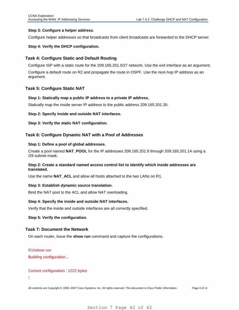
Task 9: Document the Network
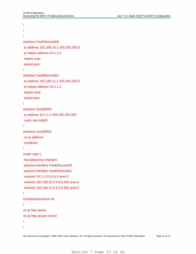
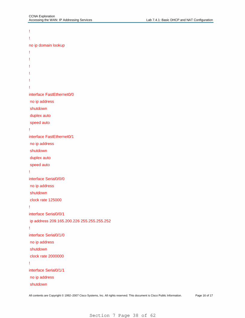
On each router, issue the show run command and capture the configurations.
R1#show run
Building configuration...
Current configuration : 1278 bytes
!
version 12.4
service timestamps debug datetime msec
service timestamps log datetime msec
no service password-encryption
!
hostname R1
!
boot-start-marker
boot-end-marker
!
enable secret 5 $1$PzEf$MYu9t.hPh8SZAbga8fG9K0
!
no aaa new-model
ip cef
!
!
!
!
no ip domain lookup
!
!
!
Section 7 Page 32 of 62
CCNA Exploration Accessing the WAN: IP Addressing Services Lab 7.4.1: Basic DHCP and NAT Configuration
ip route 209.165.200.240 255.255.255.240 Serial0/0/1
!
no ip http server
no ip http secure-server
!
!
control-plane
!
banner motd ^C
Unauthorized user access is strictly prohibited and will be prosecuted to the full extent of the law.
^C
!
line con 0
exec-timeout 15 0
password cisco
logging synchronous
login
line aux 0
line vty 0 4
exec-timeout 15 0
password cisco
logging synchronous
login
!
scheduler allocate 20000 1000
end
Task 10: Clean Up
Erase the configurations and reload the routers. Disconnect and store the cabling. For PC hosts that are normally connected to other networks, such as the school LAN or the Internet, reconnect the appropriate cabling and restore the TCP/IP settings.
In this lab, configure the IP address services using the network shown in the topology diagram. If you need assistance, refer back to the basic DHCP and NAT configuration lab. However, try to do as much on your own as possible.
Task 1: Prepare the Network
Step 1: Cable a network that is similar to the one in the topology diagram.
You can use any current router in your lab as long as it has the required interfaces shown in the topology.
Note: If you use a 1700, 2500, or 2600 series router, the router outputs and interface descriptions may look different.
Step 2: Clear all existing configurations on the routers.
Task 2: Perform Basic Router Configurations
Configure the R1, R2, and ISP routers according to the following guidelines:
Configure the device hostname.
Disable DNS lookup.
Configure a privileged EXEC mode password.
Configure a message-of-the-day banner.
Configure a password for the console connections.
Configure a password for all vty connections.
Configure IP addresses on all routers. The PCs receive IP addressing from DHCP later in the lab.
Enable OSPF with process ID 1 on R1 and R2. Do not advertise the 209.165.200.224/27 network.
Note: Instead of attaching a server to R2, you can configure a loopback interface on R2 to use the IP address 192.168.20.254/24. If you do this, you do not need to configure the Fast Ethernet interface.
Task 3: Configure a Cisco IOS DHCP Server
Configure R2 as the DHCP server for the two R1 LANs.
Step 1: Exclude statically assigned addresses.
Exclude the first three addresses from each pool.
Step 2: Configure the DHCP pool.
Create two DHCP pools. Name one of them R1_LAN10 for the 172.16.10.0/24 network, and name the other R1_LAN11 for the 172.16.11.0/24 network.
Configure each pool with a default gateway and a simulated DNS at 172.16.20.254.
Section 7 Page 41 of 62
CCNA Exploration Accessing the WAN: IP Addressing Services Lab 7.4.2: Challenge DHCP and NAT Configuration
Unauthorized user access is strictly prohibited and will be prosecuted to the full extent of the law.
^C
!
!
!
!
line con 0
exec-timeout 15 0
password cisco
logging synchronous
login
line vty 0 4
exec-timeout 15 0
password cisco
logging synchronous
login
!
!
!
end
Task 8: Clean Up
Erase the configurations and reload the routers. Disconnect and store the cabling. For PC hosts that are normally connected to other networks, such as the school LAN or the Internet, reconnect the appropriate cabling and restore the TCP/IP settings.
The routers, R1 and R2, at your company were configured by an inexperienced network engineer. Several errors in the configuration have resulted in connectivity issues. Your boss has asked you to troubleshoot and correct the configuration errors and document your work. Using your knowledge of DHCP, NAT, and standard testing methods, find and correct the errors. Make sure all clients have full connectivity. The ISP has been configured correctly.
Ensure that the network supports the following:
1. The router R2 should serve as the DHCP server for the 172.16.10.0/24 and 172.16.11.0/24 networks connected to R1.
2. All PCs connected to R1 should receive an IP address in the correct network via DHCP.
3. Traffic from the R1 LANs entering the Serial 0/0/0 interface on R2 and exiting the Serial 0/0/1 interface on R2 should receive NAT translation with a pool of addresses provided by the ISP.
4. The Inside Server should be reachable from outside networks using IP address 209.165.201.30, and to inside networks using IP address 172.16.20.254
Task 1: Prepare the Network
Step 1: Cable a network that is similar to the one in the topology diagram.
Step 2: Clear all existing configurations on the routers.
Step 3: Import the configurations below.
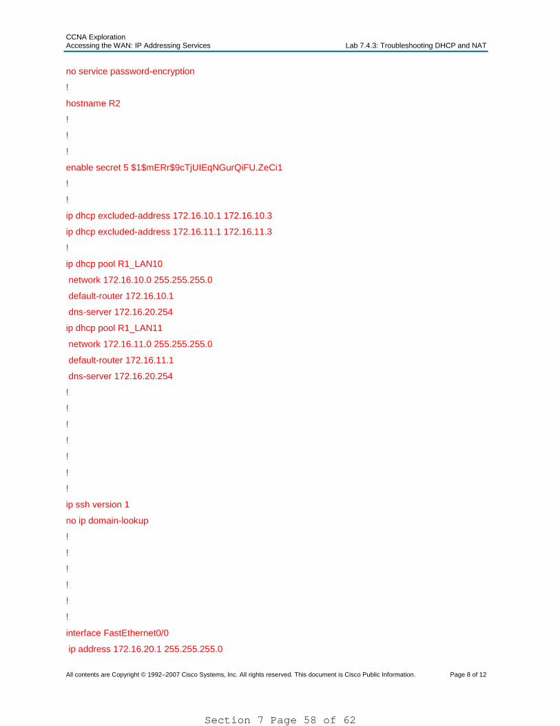
R1
hostname R1
!
enable secret class
!
no ip domain lookup
!
interface FastEthernet0/0
ip address 172.16.10.1 255.255.255.0
ip helper-address 172.16.0.2
no shutdown
!
interface FastEthernet0/1
ip address 172.16.11.1 255.255.255.0
no shutdown
!
interface Serial0/0/0
ip address 172.16.0.1 255.255.255.252
clock rate 125000
no shutdown
!
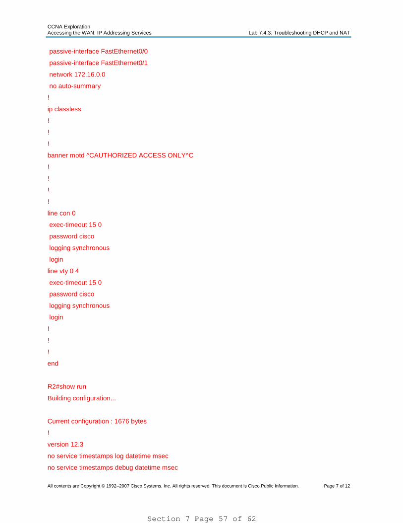
router rip
version 2
network 172.16.0.0
no auto-summary
Section 7 Page 52 of 62
CCNA Exploration Accessing the WAN: IP Addressing Services Lab 7.4.3: Troubleshooting DHCP and NAT
ip route 209.165.201.0 255.255.255.224 Serial0/0/1
!
!
!
banner motd ^CAUTHORIZED ACCESS ONLY^C
!
!
!
!
line con 0
exec-timeout 15 0
password cisco
logging synchronous
login
line vty 0 4
exec-timeout 15 0
password cisco
logging synchronous
login
!
!
!
end
Task 4: Clean Up
Erase the configurations and reload the routers. Disconnect and store the cabling. For PC hosts that are normally connected to other networks, such as the school LAN or to the Internet, reconnect the appropriate cabling and restore the TCP/IP settings.