49
Chapter 7 Electricity PHYSICS FORM 5 Cikgu Desikan Edited by SMK Changkat Beruas, Perak Cikgu Khairul Anuar In collaboration with SMK Seri Mahkota, Kuantan

Chapter 7
Electricity
PHYSICSFORM 5
Cikgu Desikan
Edited by
SMK Changkat Beruas, Perak
Cikgu Khairul AnuarIn collaboration with
SMK Seri Mahkota, Kuantan

2007 2008 2009 2010 2011 2012 2013 2014 2015
P1 4 4 4 5 5 4 3 3
P2
A 1 1 - - 1 - - 1
B - - - - - - 1 1
C - - 1 1 - 1 - -
P3A 1 - - - - - - 1
B 1 - - - - 1 - -
Analysis of Past Year Questions
Learning Objectives :
Dear students,
The thing always happens that you really believe in; and
the belief in a thing makes it happen.
1. Analysing electric fields and charge
flow
2. Analysing the relationship between
electric current and potential
difference
3. Analysing series and parallel circuits
4. Analysing electromotive force and
internal resistance
5. Analysing electrical energy and power
Chapter 7
Electricity
FO
RM
5 P
HY
SIC
S
2016

Concept Map
Dear students,
The best way to make your dreams come true is to wake up.(Paul Valery)
Electricity
Electric
Field
Electric
Current Series
Circuits
Electromotive
Force &
Internal
Resistance Electrical
Energy
Electrical
Power
Charge flow
t
QI
Potential
Difference
Parallel
Circuits
Resistance
Ohm’s Law
IRV Factors affecting
Resistance
r)I(RE
IrVE
tR
VE
RtIE
VItE
PtE
2
2
R
VP
RIP
VIP
2
2
Chapter 7
Electricity

• Matter is made up of tiny particles
called atoms.
• At the center of the atom is the
nucleus which is made up of protons
and neutrons.
• Surrounding the nucleus are particles
called electrons.
• A proton has a positive charge.
• An electron has a negative charge.
• A neutron is uncharged / neutral.
4
++
7.1 Electric Fields and Charge Flow

Electric charge
Electric Current
5
• Defined as rate of flow of electric charge
• The SI unit = Ampere, A Q
I
I ∝ Q
0t
I
I ∝1
t
• Electric charge is denoted by the symbol Q.
• The unit of electric charge is the coulomb , C.
• Charge on one electron = - 1.6 x 10⁻¹⁹ C
• Charge on one proton = 1.6 x 10⁻¹⁹ C
• An object is:
neutral, if it has equal numbers of positive and negative charges.
charged negative, if it has more negative than positive charges.
(atom gains electron)
charged positive, if it has more positive than negative charges.
(atom losses electron)
• The force acting on two bodies of the same net charges will repel each other.
• The force acting on two bodies of different net charges will attract each other.
• These forces causes movement of electrons or flow of charges.

• An electric field is represented by a
series of arrowed lines called
.
• The lines indicate both the magnitude
and direction of the field.
• Electric field lines never cross each
other.
• Electric field lines are most dense
around objects with the greatest
amount of charge.
An electric field is a region in which an
electric charge experiences an electric
force (attraction or repulsion).
Electric Field
6
To EHT power sourceMetal electrodes
Semolina grains
sprinkled on castor oil
Setup to map the electric field around metal
electrodes
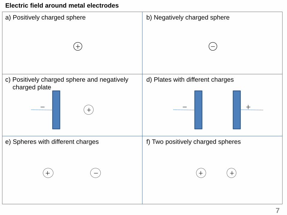
Electric field around metal electrodes
7
a) Positively charged sphere
c) Positively charged sphere and negatively
charged plate
e) Spheres with different charges
b) Negatively charged sphere
d) Plates with different charges
f) Two positively charged spheres

Effect of an electric field on a charge
A charged ball in an electric field
8
1. The EHT power supply
switched on.
2. The ping-pong ball charged
by touching it with one of
the electrodes and
released.
Observation :
Nylon
threadPing-pong ball
coated with
conducting
material
Plate
X
Plate
Y
EHT power
supply
Y X Y X Y X

9
Every great dream begins with a dreamer. Always remember, you
have within you the strength, the patience, and the passion to reach
for the stars to change the world.
Harriet Tubman
1. When the EHT power supply is switched on, plate X is positively charged and plate Y is
negatively charged. Since the ping-pong ball is neutral it remains at the center as the electric
forces acting on it are balanced.
2. When the ping-pong ball touches the positively charged plate X, the ball positively charged and
experiences a repulsive force. The ball will then pushed to the negatively charged plate Y.
3. When the ball touches plate Y, the positive charges are neutralized by the negative charges.
The ball then negatively charged and repels toward plate X.
4. The process is repeated and the ball oscillate to and fro between the two metal plates X and Y.
5. The rate of oscillation of the ping-pong ball can be increased by :
• increasing the voltage of the EHT power supply and
• decrease the distance between the two plates X and Y.
Explanation :

Candle
Effect of an Electric field on a Candle Flame
10
1. The ping-pong ball is
replaced with a candle.
2. The shape of the candle
flame is observed.
Observation :
Q P Q P
EHTWithout EHT

11
Explanation :
1. When the EHT power supply is switched on, the candle flame divided into two portions in
opposite directions.
2. The portion that is attracted to the negative plate P is very much larger than the portion that is
attracted to the positive plate Q.
3. The hot flame of the candle ionized the air molecules in its surrounding into positive and
negative ions.
4. The positive ions are attracted towards the negative plate P. At the same time, the negative ions
are attracted to the positive plate Q.
5. The movement of the ions towards the plate P and Q caused the candle flame to spread out.
Why the flame is not symmetrical?

2. When lightning strikes between two charged clouds, an electric current of 400 A flows for 0.05s.
What is the quantity of charge transferred?
3. Electric charges flow through a light bulb at the rate of 20 C every 50 seconds. What is the
electric current shown on the ammeter?
12
Solving problems involving electric charge and current
1. The current flows in a light bulb is 0.5 A.
a) Calculate the amount of electric charge that flows through the bulb in 2 hours.
b) If one electron carries a charge of 1.6 x 10⁻¹⁹ C, find the number of electrons transferred
through the bulb in 2 hours.
Exercise 7.1

7.2 Relationship Between Electric Current and Potential Difference
Potential Difference
• When a battery is connected to a bulb in a circuit, it creates electric field along the wires.
• The positive terminal P is at a higher potential and the negative terminal Q is at a lower
potential.
• The potential difference between the two terminals causes the charges to flow across the bulb
in the circuit and lights up the bulb.
• Work is done when electrical energy carried by the charges is dissipated as heat and light
energy after crossing the bulb. 13
Battery
V
Potential difference
Lower PotentialHigher Potential
P Q
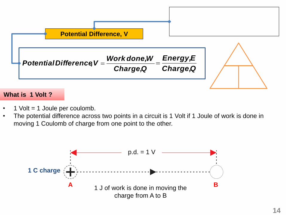
Potential Difference, V
QCharge,
Wdone, WorkV,Difference Potential
QCharge,
EEnergy,
What is 1 Volt ?
• 1 Volt = 1 Joule per coulomb.
• The potential difference across two points in a circuit is 1 Volt if 1 Joule of work is done in
moving 1 Coulomb of charge from one point to the other.
14
1 J of work is done in moving the
charge from A to B
1 C charge
p.d. = 1 V
A B

How to measure
potential
difference?
• The potential difference across two points in a circuit can be measured
using a voltmeter.
• Voltmeters must always be connected in parallel between the points
concerned.
How to measure
current?
• Ammeter measures current in amperes.
• Connected in series with a resistor or a device
• Ammeter has a low resistance so that its existence has little effect on
the magnitude of current flowing.
15
.
Measure what can be measured, and make
measureable what cannot be
measured
“Galileo Galilei
(1564 - 1642)”
V
A Ammeter
Voltmeter
Lamp

Relationship between current and potential difference
• The greater the potential difference or voltage, the greater the current flow.
• When the potential difference between two points in a circuit increases, the current flowing
through it increases.
• When the potential difference (V) between the points decreases, the current (I) decreases.
• The potential difference is directly proportional to the current flowing through it.
Ohm’s Law
I α V
constantI
VGradient
Resistance
I
V
0
16
Conductor
Condition
asGood Poor
asOhmic Non-ohmic
The ratio of the potential difference (V) across the
conductor to the current (I) flowing through it.

Disadvantage of resistance Advantage of resistance
Resistance causes some of the electrical
energy to turn into heat , so some electrical
energy is lost along the way if we are trying to
transmit electricity from one place to another
through conductor.
It is resistance that allows us to use electricity
for heat and light. The heat is generated from
electric heaters or the light that we get from
light bulbs is due to the resistance of the wire.
In a light bulb, the current flowing through a
resistance filament causes it to become hot
and then glow.
1. In a closed circuit, a 6 V battery is used to drive 40 C of electric charge through a light bulb.
How much work is done to drive the electric charge through the bulb?
2. If 72 J of work has to be done to carry 6 C of charge across two parallel metal plates, what is
the potential difference across the metal plates?
Solve problems involving W = QV
17
Exercise 7.2
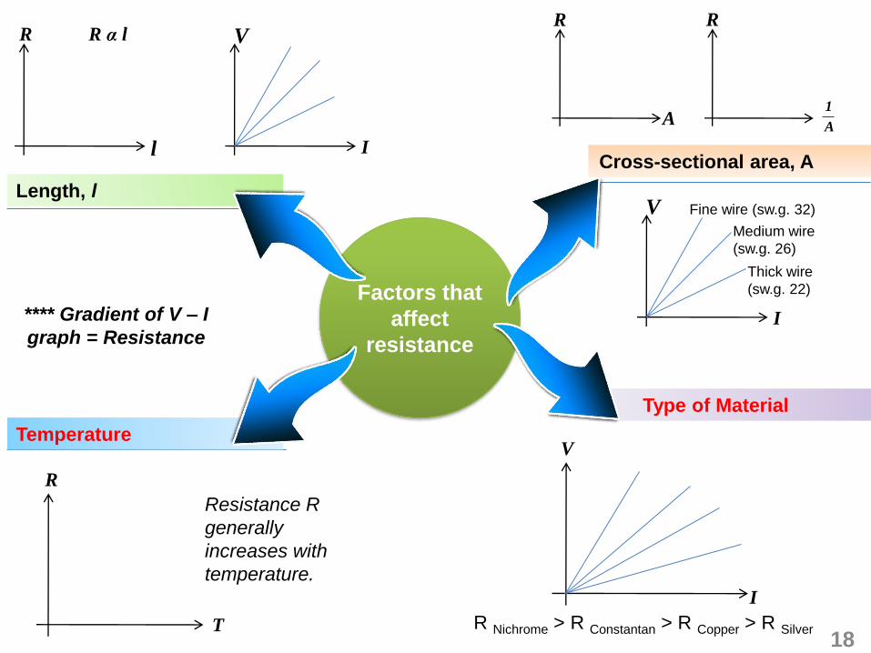
Factors that
affect
resistance
**** Gradient of V – I
graph = Resistance
R Nichrome > R Constantan > R Copper > R Silver18
Resistance R
generally
increases with
temperature.
I
V
Thick wire
(sw.g. 22)
Fine wire (sw.g. 32)
Medium wire
(sw.g. 26)
Length, l
Cross-sectional area, A
Type of Material
Temperature
l
R
I
VR α lR
A
R
A
1
R
T
V
I

• The resistance of a metal with
temperature
• The resistance of a semiconductor
with temperature.
• A superconductor is a material whose resistance
becomes zero when its temperature drops to a
certain value called the .
Advantages
• Maintain a current with no applied voltage at critical
temperature.
• Able to sustain large currents
• Smaller power loss during transmission
• Less heat produced
Super-conductor
Metals
Semiconductors
Superconductors
19
Superconducting wire
When cooled below its transition temperature, superconducting wire has zero electrical resistance.
Ex: Niobium-titanium
Applications of superconductors
R
T
R
T
R
T

Magnetic resonance imaging (MRI)
Magnetic resonance imaging (MRI) is a
technique that uses a magnetic field and
radio waves to create detailed images of
the organs and tissues within patient’s
body. Most MRI machines are large,
tube-shaped magnets. When patient lie
inside an MRI machine, the magnetic
field temporarily realigns hydrogen
atoms in his/her body. Radio waves
cause these aligned atoms to produce
very faint signals, which are used to
create cross-sectional MRI images —
like slices in a loaf of bread. 20
MAGLEV
Maglev (derived from magnetic levitation) is a transport
method that uses magnetic levitation to move vehicles without
touching the ground. With maglev, a vehicle travels along a
guide way using magnets to create both lift and propulsion,
thereby reducing friction and allowing higher speeds.
The Shanghai Maglev Train, also known as the Transrapid, is
the fastest commercial train currently in operation and has a
top speed of 430km/h.
Applications of superconductors
http://science.howstuffworks.com/transport/engines-equipment/maglev-train.htm

Solve problems involving potential difference, current and resistance.
A current of 0.5 A flows through a length of resistance wire when a potential difference of 12 V is
applied between the ends of the wire.
(a) What is the resistance of the wire?
(b) What is the current flowing through the wire if the potential difference is increased to 15 V.
21
Exercise 7.2

• Two or more resistors are connected
one end after another to form a single
path for current flow.
• The bulbs share the potential difference
from the battery, so each glows dimly.
• The brightness of each bulb is equally
the same since the same current flows
through each bulb.
• If one bulb is removed, the other goes
out because the circuit is broken.
• All the components are connected with
their corresponding ends joined together to
form separate and parallel paths for
current flow.
• Each bulb gets the full potential difference
from the battery because each is
connected directly to it. So each bulb
glows brightly.
• The brightness of each bulb in a parallel
circuit is brighter than those in a series
circuit with the same number of bulbs.
• If one bulb is removed, the other keeps
working because it is still part of an
unbroken circuit.
22
7.3 Series And Parallel Circuits
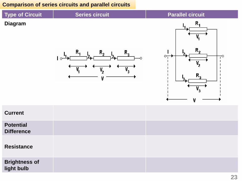
Type of Circuit Series circuit Parallel circuit
Diagram
Current
Potential
Difference
Resistance
Brightness of
light bulb
Comparison of series circuits and parallel circuits
23
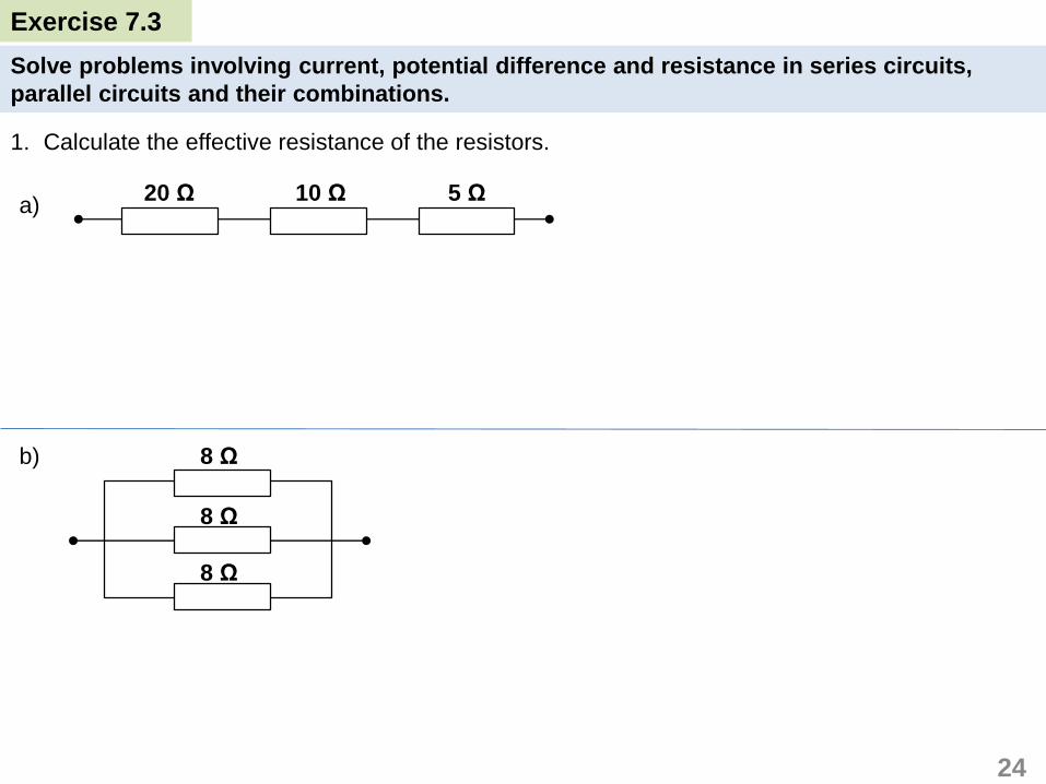
Solve problems involving current, potential difference and resistance in series circuits,
parallel circuits and their combinations.
1. Calculate the effective resistance of the resistors.
a)
b)
24
20 Ω 10 Ω 5 Ω
8 Ω
8 Ω
8 Ω
Exercise 7.3

c)
d)
25
8 Ω
8 Ω
4 Ω
10 Ω8 Ω
8 Ω
20 Ω
8 Ω
4 Ω

2. Three resistors R1, R2 and R3 are connected in series to a 6 V battery.
Calculate
(a) the effective resistance, R of the circuit,
(b) the current, I in the circuit
(c) the potential difference across each resistor,
V1, V2 and V3.
26
2 Ω 4 Ω 6 Ω
A
V1
6 V
I
V2 V3
R1 R2 R3

3. The three resistors R1, R2 and R3 are connected in parallel to the battery.
Calculate
(a) the potential difference across each resistor,
(b) the effective resistance, R of the circuit
(c) the current, I in the circuit
(d) the current I1 , I2 and I3 passing through each
resistor.
27
2 Ω
4 Ω
6 Ω
A
6 V
I
R1
R2
R3
I1
I2
I3

Electro-motive force (e.m.f), E
• Unit of e.m.f. is the Volt, V = J C-1
• The voltage label on a battery or cell indicates its
e.m.f
• The label 1.5 V on a dry cell indicates the e.m.f. of
the cell is 1.5 V.
• A cell has an e.m.f. of 1.5 V if a flow of 1 C of
charge produces 1.5 J of electrical energy to the
whole circuit.
What does the label 1.5 V on the battery mean?
Comparison of open circuit and closed circuit
28
7.4 Electromotive Force and Internal Resistance

• _______current flows through the circuit
• Voltmeter reading is __________
• Reading of the voltmeter = e.m.f. of the
battery
• e.m.f. =
• Current flows through the circuit
• Voltmeter reading is _________
• Reading of the voltmeter will drop a little.
• Reading of the voltmeter = potential
difference across the lamp
• Potential difference across the lamp
=
29
.A creative man is motivated by the desire to
achieve, not by the desire to beat others.“”~ Ayn Rand
Open circuit Closed circuit
V V
1.5 V 1.2 V
Battery Battery

Position of
switch State of the bulb
Ammeter
reading/A
Voltmeter
reading/V
Open
Closed
Observations
30
Distinguish differences between e.m.f. and potential difference
Procedures
1. Switch S is let in the
open position. What
happens to the bulb
is observed. The
readings of the
ammeter and the
voltmeter are
recorded.
2. Switch S is closed
and what happens
to the bulb is
observed. The
readings of the
ammeter and the
voltmeter are
recorded.
V
A
Circuit diagram
Electrical circuit
S

Discussions
Why does the ammeter
reading is zero when switch S
is open and have a reading
when switch S is closed?
The reading of the ammeter when switch S is open is zero
because there is of charge in an open circuit,
Current in circuit is .
When switch S is closed, there is an ammeter reading due to the
flow of charge in the closed circuit produce flow of current.
Compare the difference in the
two voltmeter readings
measured.
The reading of the voltmeter when switch S is open is ________
than when switch S is closed.
What is the drop in potential
difference?
=
=
Why there is drop in potential
difference?
1. Drop in potential difference across the cell is caused by the
___________________________of the cell.
2. e.m.f. = 1.5 V means the cell gives 1.5 J of electrical energy to
each coulomb that passes through it.
3. The _____________ that flows through the circuit also flows
through the battery.
4. Some of the energy per charge the battery provides will be
used to overcome the __________________________of the
battery and change to ___________ energy.
5. Therefore, The energy dissipated in the resistor or bulb is
_________ than e.m.f. (1.5J per coulomb).
Drop in p.d. = e.m.f - potential difference (bulb)
31
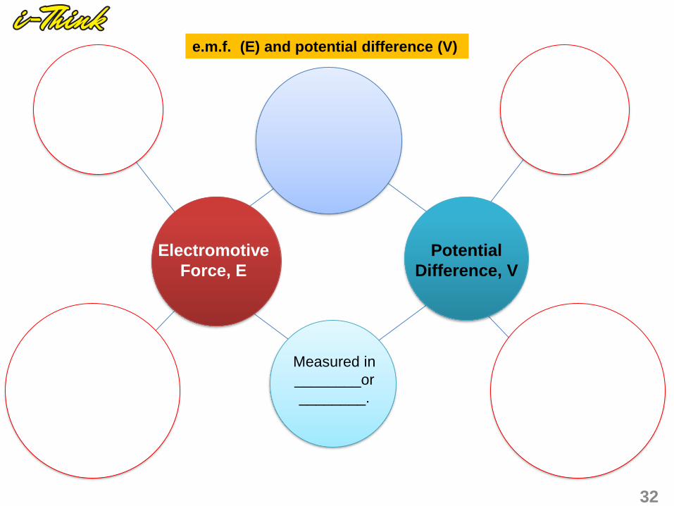
Electromotive
Force, E
32
Potential
Difference, V
Measured in
________or
________.
e.m.f. (E) and potential difference (V)

Internal Resistance, r
1. The internal resistance, r of a source or battery is the against the moving
charge due to the electrolyte in the source or cell.
2. Work is needed to drive a charge against the internal resistance.
3. This causes a drop in potential difference across the cell as the charge flows through it and
loss of heat energy in the cell.
Equation relates, E, V, I, and r
E.m.f of the cell = E
P.d to the external circuit = V
Drop in p.d. inside the cell = Ir
Ir = E – V
Drop in p.d. = e.m.f - p.d. across resistor
V = IR
33I/A
V/ V
0
R
Er
I
Dry cell

1. A cell with e.m.f. 2 V and internal resistance 1 Ω is
connected to a resistor of 4 Ω. Determine
a) the reading on the voltmeter
b) the current across the 4 Ω resistor
34
Exercise 7.4
V
R
r

2. A bulb M is connected to a battery by means of a switch.
A voltmeter is also connected across the battery. When
the switch is open, the voltmeter reads 6.0 V. When the
switch is closed, the voltmeter reads 4.8 V.
a) What is the e.m.f. of the battery?
b) If the resistance of the bulb M is 8 Ω, what is the
current passing through M when the switch is closed?
c) Find the value of the internal resistance, r, of the
battery.
35
V
Bulb, M
r
Switch

3. When switch S is opened, the voltmeter reading
is 1.5 V. When the switch is closed, the voltmeter
reading is 1.35 V and the ammeter reading is
0.3 A. Calculate:
a) e.m.f
b) internal resistance
c) resistance of R
4. Figure shows a graph of V against I for a dry cell.
Determine:
a) the e.m.f of the cell
b) the internal resistance of the cell
I/A
V/ V
0
1.5
0.9
0.6
36
V
A
R
S

Comparison between total e.m.f and total internal resistance in a series and parallel circuit.
Total e.m.f =
Total r =
Total e.m.f =
Total r =
37
1.5 V 1.5 V
0.5 Ω 0.5 Ω
1.5 V 0.5 Ω
1.5 V 0.5 Ω
Series Connection Parallel Connection
Each cell has E = 1.5 V and r = 0.5 Ω

Electrical energy
• Electrical energy is defined as the ability of the electric current to do work.
• It is supplied by a source of electricity such as cell or battery when current flows in a closed
circuit.
• It can be converted by an electrical appliance into other forms of energy such as heat, light,
mechanical when current flows in it.
Relation-ship between electrical energy, voltage, current and time.
• The potential difference, V across two
points is defined as the energy, E
dissipated or transferred by 1 C of charge,
Q that moves through the two points.
• Current is the rate of charge flow.
• From ohm’s law,
IRV
R
VI
ItQ
• The unit of electrical energy is Joule, J
VItE
38
7.5 Electrical Energy and Power

Electric power
• Power is the rate of electrical energy dissipated or transferred.
For resistors and lamps, combine P = VI with
V = IR or I=V/R
Time
EnergyPower unit = J s-1
= Watt (W)
Power rating
An electrical kettle which is marked
240 V 1500 W means
Formula for energy consumed
The amount of electrical energy consumed in a given :
Energy consumed = Power rating x time
IRV
R
VI
39

Comparison power rating and energy consumption of various electrical appliances
• The larger the power rating in the electrical appliance, the more energy is used every second.
• The longer the usage time, the more electrical energy is consumed.
AppliancePower
rating / W
Time
/ h
Energy
consumption / kWh
Fan 50 1
Television 100 1
Computer 200 1
Air condition 1000 1
Washing machine 1 800 ½
Water heater 3600 ½
Total
Compare power rating and energy consumption of various electrical appliances
What is kWh?
• 1 kilowatt-hour represents the amount of energy consumed in 1 hour by an electrical
appliance at the rate of 1 kilowatt.
• 1 kWh = 1 unit energy
• E = Pt
• 1 kWh = 1 kW x 1 hr = 1000 W x 3600 s = 3.6 x 10⁶ J
40
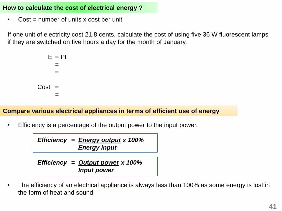
How to calculate the cost of electrical energy ?
• Cost = number of units x cost per unit
If one unit of electricity cost 21.8 cents, calculate the cost of using five 36 W fluorescent lamps
if they are switched on five hours a day for the month of January.
E = Pt
=
=
Cost =
=
Compare various electrical appliances in terms of efficient use of energy
• Efficiency is a percentage of the output power to the input power.
Efficiency = Energy output x 100%
Energy input
Efficiency = Output power x 100%
Input power
• The efficiency of an electrical appliance is always less than 100% as some energy is lost in
the form of heat and sound.
41

Solve problem involving electrical energy and power
1. An electric kettle is connected across a 240 V power supply. If the resistance of the heating
element is 40 Ω, calculate
a) the current flowing through the element
b) the quantity of heat produced in 10 minutes
42
Exercise 7.5

2. An immersion heater has a power rating of 240 V, 750 W.
a) What is the meaning of its power rating?
b) What is the resistance of the immersion heater?
c) What is the electrical energy consumed in 15 minutes?
3. An appliance with a power of 2 kW is used for 10 minutes, three times a day. If the cost of
electricity is 25 cents per unit, what is the cost of operating the appliance in the month of
April?
43

Describe ways of increasing energy efficiency
• The term energy efficiency refers to gaining a higher level of useful outputs using less input.
This can be achieved using efficient devices.
• By increasing energy efficiency, not only are we reducing our cost but also we assist the
industry in energy conservation.
44
Several ways to increase energy efficiency includes:
1. Use more energy efficient lightings
Replace regular incandescent (filament) light bulbs with compact fluorescent light
bulbs.
2. Proper utilization of all electrical appliances
Run your washing machine only when it is fully loaded & Iron your clothes only when
you have at least a few pieces to iron.
3. Limit excessive usage of air-conditioning and lighting by switching them off upon
leaving the room, thus reducing energy loss.
4. Regular cleaning of air filters in air-condition units and clothes dryers.
5. Defrost refrigerators regularly, check the seal on refrigerator doors and vacuum the
grille behind refrigerators.
6. Improve ventilation and air flow.
Less
efficient
Efficient

What are fuses? • A fuse is a short piece of thin wire which _____________ and
___________ if current of more than a certain value flows through
it.
• If a short circuit develops in the appliance, a current which is too
high will flow. The fuse will melt and prevents overheating of the
wire that can cause a fire.
• If an electrical appliance is rated 960 W and 240 V then current in
normal use is 4.0 A. The fuse suitable for use must slightly
____________ than the normal current flowing through the
appliance (.ie 5 A fuse ).
Three-pin plug • Live wire, L (brown). A current flows
through the circuit
• Neutral wire, N (blue). It is a zero
potential difference.
• Earth wire, E (green). Safety wire which
connects the metal body of the appliance
to earth. If a live wire touches the metal
body of appliance, a large current would
immediately flow to the earth and breaks
the ____________. This will prevent a
person from _____________________.
45

1 A student carries out an experiment to study the relationship between the length of a conductor, ℓ, with
the resistance, R. The circuit is connected as shown in Diagram 1.1.
Paper 2 Section B
Additional Exercise
Diagram 1.1
Constantan wire
Ammeter
Voltmeter
d.c. power supply
Rheostat
46

Diagram 1.5
ℓ = 70.0 cm
Diagram 1.6
ℓ = 80.0 cm
The length of the constantan wire between P and Q is adjusted so that its length, ℓ = 40.0 cm. The
switch is on and the rheostat is adjusted until the current, I, flowing in the circuit is 0.2 A. The potential
difference, V, across the wire is recorded.
The procedure is repeated by varying the values of ℓ to be 50.0 cm, 60.0 cm, 70.0 cm and 80.0 cm.
For each length of wire used, the rheostat is adjusted so that the current is at a constant value of
0.2 A. The corresponding readings of the voltmeter are shown in Diagram 1.2, 1.3, 1.4, 1.5 and 1.6.
Diagram 1.2
ℓ = 40.0 cm
Diagram 1.4
ℓ = 60.0 cm
Diagram 1.3
ℓ = 50.0 cm
47
V V V
V V

(a) Based on the aim and the procedure of the experiment state the:
(i) The manipulated variable [1 mark ]
(ii) The responding variable [1 mark ]
(iii) The constant variable [1 mark ]
(b) Record the reading of the voltmeter, V in Diagram 1.2, 1.3, 1.4, 1.5 and 1.6 when different length of wires, ℓ
are used. In each case, calculate the resistance, R of the wire where:
Tabulate your results for ℓ, V, I and R in the space below.
[6 marks]
(c) On a graph paper, plot a graph of R against ℓ. [5 marks]
(d) Based on your graph, state the relationship between R and ℓ. [1 mark]
(e) State one precaution that should be taken to obtain the accurate readings of V. [1 mark]
I
VR
48

49


