13
136 Chapter 7 Heat transfer application of synthesized Gd doped Mn-Zn ferrofluids
136
Chapter 7
Heat transfer application
of synthesized Gd doped
Mn-Zn ferrofluids

137
CHAPTER-7
7.1 INTRODUCTION
Natural convection heat transfer is an important phenomenon in engineering and industry
with widespread applications in diverse fields, such as, geophysics, solar energy,
electronic cooling, nuclear energy and other industrial systems in various sectors.
Limitation against enhancing the heat transfer in such engineering systems is inherently
poor thermal conductivity of conventional fluids, including oil, water and ethylene glycol
mixture. Therefore, for more than a century since Maxwell’s theories in 1873, scientists
and engineers have made great efforts to break this fundamental limit by dispersing
micrometer sized particles in liquids. However, the major problem with the use of such
large particles is the rapid sedimentation of these particles in fluids. Maxwell’s concept is
old but what is new and innovative is the concept of nanofluids is the idea of using
nanometer-sized particles to create stable and highly conductive suspensions, primarily
for suspension stability and for dynamic thermal interactions. Recognizing an excellent
opportunity to apply nanotechnology to thermal engineering, Eastman et al. [1,2] were
the first who conceived the novel concept of nanofluid by hypothesizing that it is possible
to break down these century-old technical barriers by exploiting the unique properties of
nanoparticles.
Nanofluids are dilute colloidal suspension of nanomagnetic particles of size smaller than
100 nm. This suspension of nanosize particles have recently been demonstrated to have
thermal conductivities far superior to that of the fluid alone. This and their other
distinctive features offer unprecedented potential for many applications in various fields
including energy, bio- and pharmaceutical industry, and chemical, electronic,
environmental, material, medical and thermal engineering [2-7]. With ever-increasing
thermal loads due to smaller features of microelectronic devices and higher power
outputs, thermal management of such devices to maintain their desired performance and
durability is one of the most important technical issues in many high-technology
industries such as microelectronics, manufacturing transportation.

138
John Philip et al. (2007) worked on nanomagnetic fluids in IGCAR, Kalapakkam [8].
They studied the effect of very small magnetic field on hexadecane based ferrofluids.
They found out that by applying very small magnetic field, thermal conductivity of
ferrofluid can be increased, which can be used to produce efficient heat sinks for many
new generation devices and system. Popplewell at al. (1982) at University College of
North Wales (U. S.A) measured thermal conductivity of ferrofluid containing different
carrier fluids [9]. They observed that ferrofluid based on hydrocarbons has the maximum
thermal conductivity with respect to their counterparts. Suomes et al. (2007) at North
Dacota state university (U.S.A.) studied that the effects of additive like carbon nanotubes
to the ferrofluid [10]. They found that the addition of CNT increased heat conductivity on
the thermal conductivity of ferrolfuids. Los Almos science describes the alignment of
ferrofluid in the presence of a magnetic field [11]. Djurec at al. (2007) at University of
Zegreb, Crotia measured the thermal conductivity of CoFe2O4 and Fe3O4 based
nanomagnetic fluids [12]. They concluded that strength of conductivity enhancement of
FF can be increased by increasing the number of nanomagnetic particles in it. Y. Ding et.
al. at the University of Leeds, studied the heat transfer intensification using nanofluids
[13]. They show that the boiling heat transfer of the ferrofluid can be enhanced at the
nucleate regime. Liu. et. al (2006) studied the enhancement of thermal conductivity of
nanofluids using chemical reduction method at ITRI, Taiwan. Copper atoms are produced
in water by reduction of copper acetate, which then precipitate to form copper
nanoparticles which can be used to increase the thermal conductivity of the ferrofluid.
Trisaksri et. al. at King Monkur’s University, Thailand, studied the nucleate pool boiling
heat transfer nanofluids. They concluded that the nucleate pool boiling heat transfer
declines with increasing particle concentration. Kosar et. al. studied the flow and
convective heat transfer characteristics of water based ferrofluid . They observed that due
to flattening of velocity profile convective heat coefficient enhancement exceeds the
thermal conductivity coefficient.
The main objective of the experiment discussed in this chapter was to enhance the thermal
conductivity of kerosene based ferrofluid using a small permanent magnet of different
orientation. The arrangement of these magnetic fields is associated with the formation of
proper channels through the ferrofluid which makes way for the transfer of heat.
139
In the absence of a magnetic field, the magnetic moments of the particles are randomly
distributed and the fluid has no net magnetization [14]. The magnetization of the FF
responds immediately to the change in the applied magnetic field and when the applied
field is removed, the moments randomize quickly. The objectives of carrying out these
experiments were to understand the direction of formation of these channels and the
process transfer of heat through these channels.
The future coolants for electronic devices and engines will be magnetic nanofluids, as
they more efficiently conduct heat than air [15, 16]. With the shrinkage in size of
electronic chips, there will be more demand for very effective heat sinks. Such heat sinks
can be made using high heat conducting nanomagnetic fluids. Thus requirement of high
heat dissipation find application in new generation devices like NEMS and MEMS device
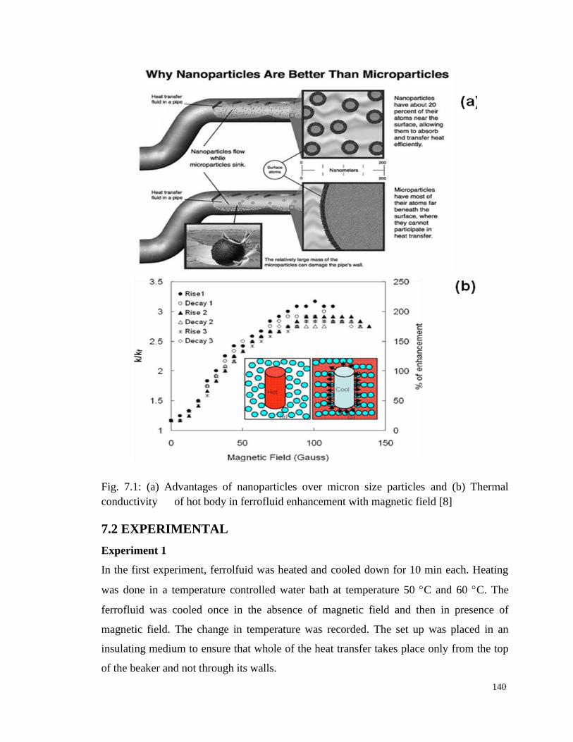
systems. The tentative mechanism of heat transfer by the ferrofluids is shown in Fig.
7.1(a,b) and why they are better is discussed in the following section. Fig. 7.1 (a) explains
the advantage of nanosized magnetic particles in ferrofluids due to large surface to
volume ratio as compared to micron sized particles. This leads to more surface activity of
nanoparticles in the rapid transfer of heat. Fig. 7.1 (b) demonstrates the alignment of
magnetic nanoparticles of ferrofluids into specific arrays, to form channels or paths in the
presence of magnetic field. These channels increase the fast heat dissipation through the
fluid and hence the hot body placed inside the ferrofluids cools down faster in the
presence of magnetic field. Gd3+
ion doped Mn-Zn ferrite are technologically important
due to high pyromagnetic coefficient (M/T)H and has a low-curie temperature [17,18].
The doping of Gd3+
ions in Mn-Zn ferrite improves the thermomagnetic properties of
material.
To confirm this, kerosene based Gd3+
doped Mn-Zn ferrofluid developed and studied as
effective heat sink. Five different experimental setups with different magnetic field
environments were proposed and used to find the best results i.e. how effectively the heat
can be transferred by the ferrofluid in the presence of magnetic field. The details of the
different experimental steps are described in the following experiments as:
140
Fig. 7.1: (a) Advantages of nanoparticles over micron size particles and (b) Thermal
conductivity of hot body in ferrofluid enhancement with magnetic field [8]
7.2 EXPERIMENTAL
Experiment 1
In the first experiment, ferrolfuid was heated and cooled down for 10 min each. Heating
was done in a temperature controlled water bath at temperature 50 C and 60 C. The
ferrofluid was cooled once in the absence of magnetic field and then in presence of
magnetic field. The change in temperature was recorded. The set up was placed in an
insulating medium to ensure that whole of the heat transfer takes place only from the top
of the beaker and not through its walls.

141
After the cooling down of the ferrofluid, to the room temperature, the process was
repeated and it was ensured that the FF reaches the same temperature as in the previous
case. After 10 minute of heating, FF was removed from the water bath and this time, a bar
magnet was placed under the beaker containing the FF. The change in temperature was
noted for 10 min of cooling in the insulated medium. Fig. 7.2 (a) exhibits the
experimental set schematic of this case.
Fig. 7.2: Experimental set up (a) Experiment 1, (b) Experiment 2, (c) experiment 3,
experiment number 4 (d) Experiment 5
Experiment 2
Kerosene based Gd3+
doped Mn-Zn ferrofluid was heated to different temperatures in the
absence of magnetic field for 10 minute each. The change in temperature has been noted
at an interval of every 1 minute and 3 min. respectively. The overall change in
temperature after 10 minutes. The heated FF taken in test tube was allowed to cool down
to the room temperature in the ring magnet surrounding. The decrease in temperature was
recorded at the end of 1 min and 3 minute respectively for different temperatures. Fig. 7.2

142
(b) shows the experimental set up for this case. The test tube containing ferrofluid was
completely surrounded by the ring magnets.
Experiment 3
In this experiment FF was heated to a certain temperature in the water bath and then
placed in an insulated container. A test tube containing water at room temperature was
placed inside the test tube containing FF and the temperature of water was noted down
after every minute for 5 minutes.
The same experiment was repeated with the ring magnets surrounding the FF and kept in
insulation containing a test tube of water at room temperature. This experiment was done
to predict the heat transfer from the hot FF to comparatively colder water. The magnets
were put to observe the change in temperature of water due to the formation of channels
in the FF due to the presence of water. The experimental set for these case is shown in
Fig. 7.2 (c). The test tube containing the hot ferrolfuid was completely surrounded by the
ring magnets.
Experiment 4
An experimental set up similar to experiment 3 was used. But in this experiment, water
was heated in the bath and the test tube containing hot water was put inside the test tube
containing FF at room temperature. Whole setup was placed inside insulation to facilitate
heat transfer only through the channels formed when ring magnet were placed completely
surrounding the test tube containing the FF. The heating time was 10 minutes and
temperature readings were taken after every 2 minutes.
Experiment 5
In experiment 5, like experiment 4 water was heated for 10 minutes at different
temperatures and placed inside the test tube containing FF to cool down. The setup was
insulated and temperature readings were taken after every one and two minutes
respectively.
Water was then allowed to come the room temperature and then was heated again for 10
minutes to the same temperatures as above. After ten minutes, the water test tube was
removed from the bath and the ring magnets were placed surrounding the water

143
completely. This arrangement was then placed inside the FF and temperature readings
were taken every minute. The change in temperature was noted for 10 and 15 minutes.
The precautions were taken so that the ferrofluid does not stick to magnet. Fig. 7.2 (d)
shows the experimental setup for this experiment.
7.3 RESULTS AND DISCUSSION
Fig. 7.3 and Fig. 7.4 present the curve between decrease in temperature vs. time for the
ferrofluid sample cooled in the absence and presence of magnetic field (1000 G) as
obtained from Experiment 1 when water bath temperature was 60 C and 50 C
respectively.
Fig. 7.3: Decrease in temperature of ferrofluid at 60 C bath temperature (a) absence
of magnetic field and (b) in the presence of magnetic field with time
Fig. 7.4: Decrease in temperature of ferrofluid at 50 C bath temperature (a) absence
of magnetic field and (b) in the presence of magnetic field with time.
144
These graphs clearly indicate that in the presence of a magnetic field, the temperature of
the ferrofluid drops down to a lower value in the same time. This can be explained by the
formation of channels by the alignment of ferrofluid nanoparticles in the presence of
magnetic field. These channels help in fast dissipation of heat. The results are more
favorable at higher bath temperature.
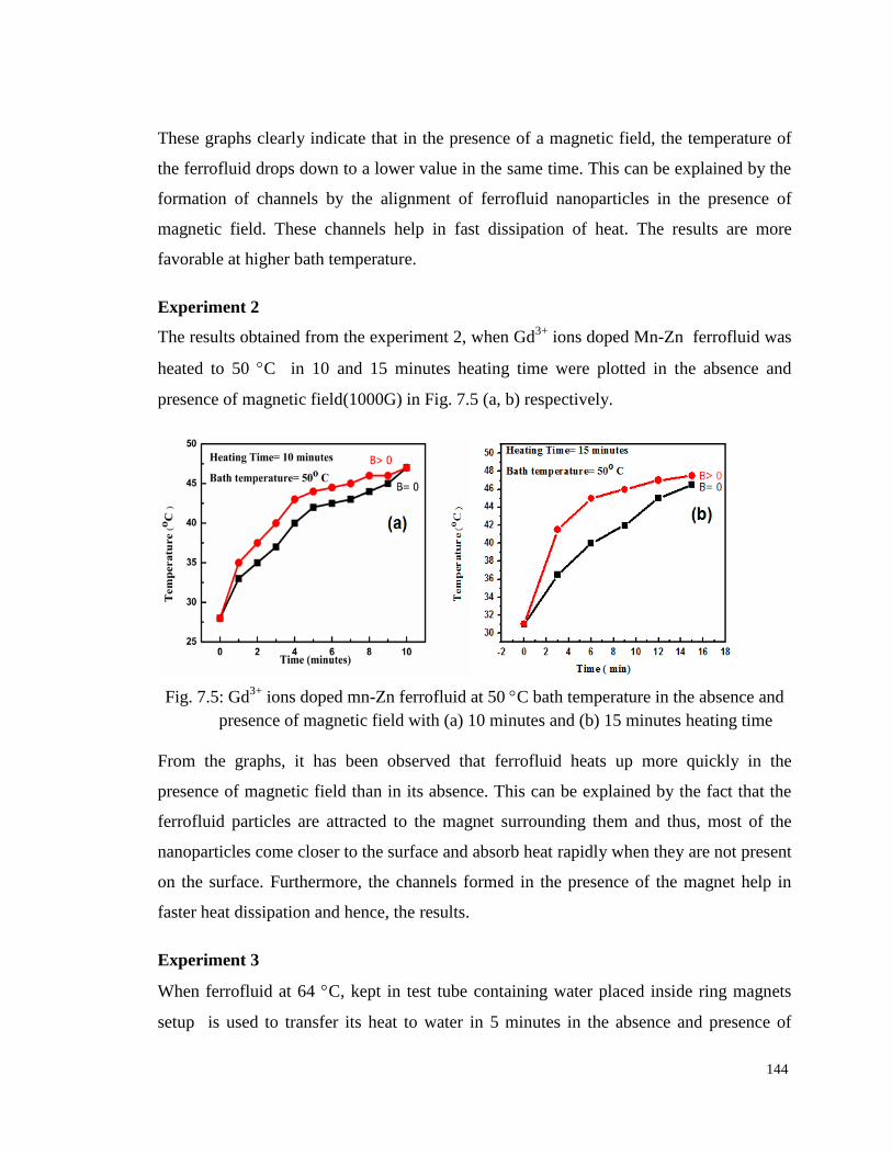
Experiment 2
The results obtained from the experiment 2, when Gd3+
ions doped Mn-Zn ferrofluid was
heated to 50 C in 10 and 15 minutes heating time were plotted in the absence and
presence of magnetic field(1000G) in Fig. 7.5 (a, b) respectively.
Fig. 7.5: Gd3+
ions doped mn-Zn ferrofluid at 50 C bath temperature in the absence and
presence of magnetic field with (a) 10 minutes and (b) 15 minutes heating time
From the graphs, it has been observed that ferrofluid heats up more quickly in the
presence of magnetic field than in its absence. This can be explained by the fact that the
ferrofluid particles are attracted to the magnet surrounding them and thus, most of the
nanoparticles come closer to the surface and absorb heat rapidly when they are not present
on the surface. Furthermore, the channels formed in the presence of the magnet help in
faster heat dissipation and hence, the results.
Experiment 3
When ferrofluid at 64 C, kept in test tube containing water placed inside ring magnets
setup is used to transfer its heat to water in 5 minutes in the absence and presence of
145
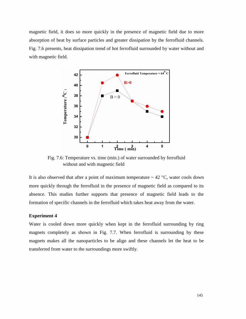
magnetic field, it does so more quickly in the presence of magnetic field due to more
absorption of heat by surface particles and greater dissipation by the ferrofluid channels.
Fig. 7.6 presents, heat dissipation trend of hot ferrofluid surrounded by water without and
with magnetic field.
Fig. 7.6: Temperature vs. time (min.) of water surrounded by ferrofluid
without and with magnetic field
It is also observed that after a point of maximum temperature ~ 42 C, water cools down
more quickly through the ferrofluid in the presence of magnetic field as compared to its
absence. This studies further supports that presence of magnetic field leads to the
formation of specific channels in the ferrofluid which takes heat away from the water.
Experiment 4
Water is cooled down more quickly when kept in the ferrofluid surrounding by ring
magnets completely as shown in Fig. 7.7. When ferrofluid is surrounding by these
magnets makes all the nanoparticles to be align and these channels let the heat to be
transferred from water to the surroundings more swiftly.

146
Fig. 7.7: Temperature vs. time (min.) of ferrofluid surrounded by water in the absence
and in the presence of magnetic field at 60 C bath temperature
Experiment 5
Fig. 7.7: Temperature vs. time (min.) of ferrofluid surrounded by water heated at 60 C
and 70 C in 10 minutes heating time, in the absence and in the presence of
magnetic field.
7.4 CONCLUSIONS
Kerosene based Gd3+
ion doped Mn-Zn ferrofluids has been tested for its suitability in
heat transfer application. It is observed that there is enhancement in the heat dissipation
through the ferrofluids in the presence of magnetic field. The time taken by a hot object
(water) to reach a specific temperature in the presence of magnetic field is just half of that

147
what it had taken in its absence. Thus, it is seen that the heat dissipation is increased in the
presence of a very small magnetic field which can lead to the development of futuristic
application of ferrofluids as heat sink in the electronic devices.
148
REFERENCES
[1] Z. Haddad, H. .Oztop, E. Abu-Nada, A. Mataoui , Renewable and Sustainable
Energy Reviews 16 (2012) 5363.
[2] J.A. Eastman, SUS Choi, S. Li, W. Yu, L. J. Thompson. Appl. Phys. Letters
78 (2001) 78 718.
[3] S.K. Das, S.U.S. Choi, W. Yu, T. Pradeep, Nanofluids: Science and Technology,
John Wiley & Sons, Inc., Hoboken, New Jersey, 2008.
[4] J. Fan, L.Q. Wang, Review of heat conduction in nanofluids, ASME J. Heat
Transfer 133 (2011) 040801.
[5] G.P. Peterson, C.H. Li, Heat and mass transfer in fluids with
nanoparticlesuspensions, Adv. Heat Transfer 39 (2006) 257–376.
[6] U.S. Choi, Z.G. Zhang, P. Keblinski, Nanofluids, in: H.S. Nalwa (Ed.),
Encyclopedia of Nanoscience and Nanotechnology, American Scientific
Publishers, 2004, pp. 757.
[7] J. Fan, L. Wang, Int. J. of Heat and Mass Transfer 54 (2011) 4349.
[8] J. Philips, P. D. Sharma, Appl. Phys. Letter 92 (2008) 043108.
[9] J. Poplewell, A. Al. Qenaie,S. W. Charless, R. Moskowiz and K. Raj, colloid and
Polymer Science, 260 (1982) 333.
[10] Enhancement of fluid thermal conductivity by addition of single and hybrid
nano derivatives, Thermochimica acta, 45-55.
[11] Necia Grant Cooper, Ferrofluid anew alignment technique, Los Almos Science
No. 19 (1990)
[12] Thermal conductivity measurements of CoFe2O4 and Fe3O4 based nanomagnetic
fluids CCACAA (3-4) 529.
[13] H. Yarmand, S. Gharehkhani, S. N. Kazi, E. Sadeghinezhad, The scientic J.,
publish online, dio.10.11550014059593.
[14] http://www.ferotecc.com/technology/ferrofluid.
[15] www.ferrotec.com/prodcut/ferrofluid/audio/audiobenifits
[16] http://www.liquidreserach.com.
[17] D. Zins, R. Massart, E. Auzans, E. Blums, J. Mater. Sci. 34 (1999) 1253.
[18] E. Calderon-Ortiz, O. P. Perez, P. Voyles, G. Gutierrez, M. S. Tomar,
Microelect. J. 40 (2009) 677.


![Chapter 7shodhganga.inflibnet.ac.in/bitstream/10603/11620/12/12_chapter 7.p… · layer on the surface having very high levels of residual stresses [106], sub-micron sized grain structure](https://static.documents.pub/doc/80x56/6050e6e63bd6594277733a0e/chapter-7p-layer-on-the-surface-having-very-high-levels-of-residual-stresses.jpg)
