56
AUCSC Chapter 8 Cathodic Protection System Maintenance and Troubleshooting Procedures
AUCSC
Chapter 8 Cathodic Protection System
Maintenance and Troubleshooting Procedures
Maintenance Program
• Periodic Surveys
• Coating Maintenance
• Rectifier and Anode Bed Maintenance
• Galvanic Anode Maintenance
• Test Station Maintenance
Coating Maintenance
• Above and Below Ground Coatings
• All damage should be repaired at time of discovery
• Repair should be as good or better than existing coating
• Repair crew should be trained in proper preparation and application (READ THE INSTRUCTIONS)
Coating Maintenance
• Keep records of type of coatings found and condition
• Documentation
– Existing coating
– Repair coating
– Environmental conditions
– Date
– Weather conditions
Rectifier and Anode Bed Repair
• Impress current anode bed usually limited to a visual inspection
• Recent construction activity
• New underground structures near anode bed
• Inspect overhead power service
Galvanic Anode Maintenance
• Anode bed limited to visual inspect as previous mentioned
• Header cables should be large diameter wire (ex. #8 or #6 AWG)
• Test stations should have anode connections cleaned, free of corrosion (copper antiseize)
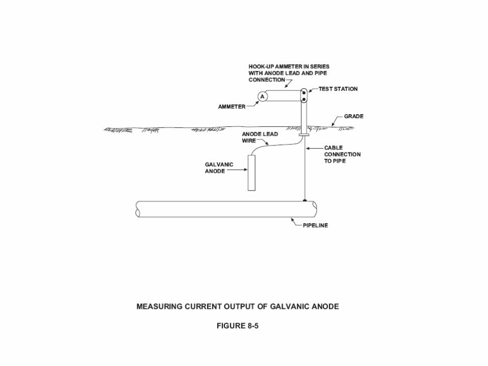
• Measure and record anode current output
– To determine anode life and consumption rate
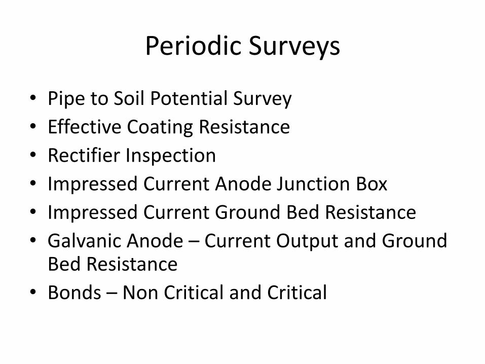
Periodic Surveys
• Pipe to Soil Potential Survey
• Effective Coating Resistance
• Rectifier Inspection
• Impressed Current Anode Junction Box
• Impressed Current Ground Bed Resistance
• Galvanic Anode – Current Output and Ground Bed Resistance
• Bonds – Non Critical and Critical
Periodic Surveys
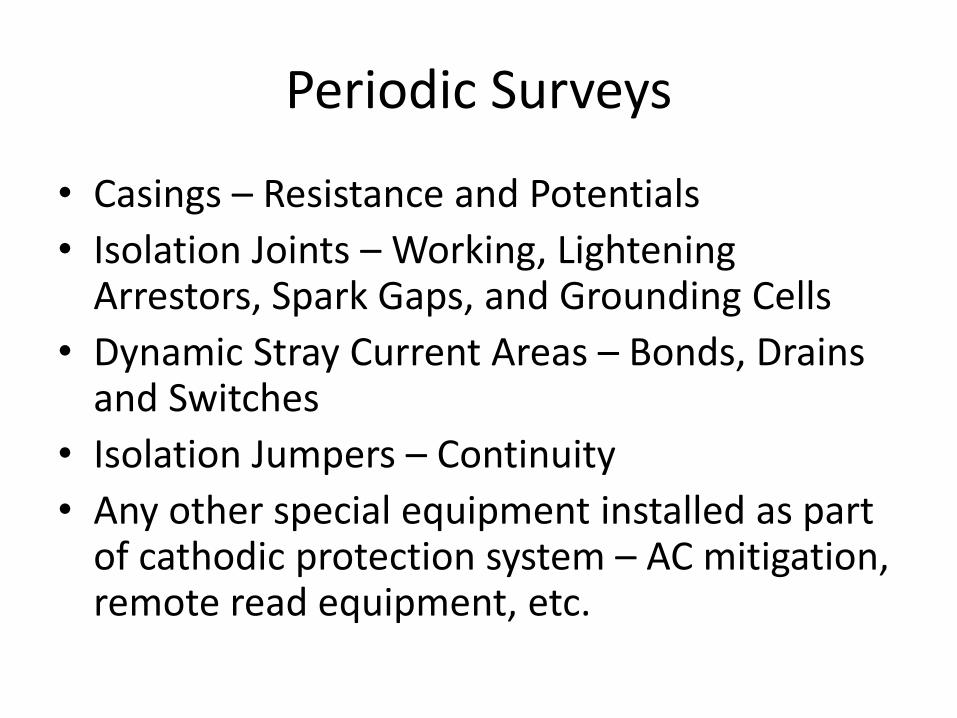
• Casings – Resistance and Potentials
• Isolation Joints – Working, Lightening Arrestors, Spark Gaps, and Grounding Cells
• Dynamic Stray Current Areas – Bonds, Drains and Switches
• Isolation Jumpers – Continuity
• Any other special equipment installed as part of cathodic protection system – AC mitigation, remote read equipment, etc.
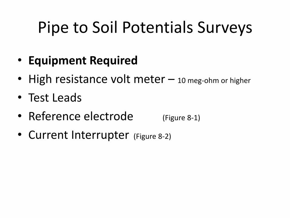
Pipe to Soil Potentials Surveys
• Equipment Required
• High resistance volt meter – 10 meg-ohm or higher
• Test Leads
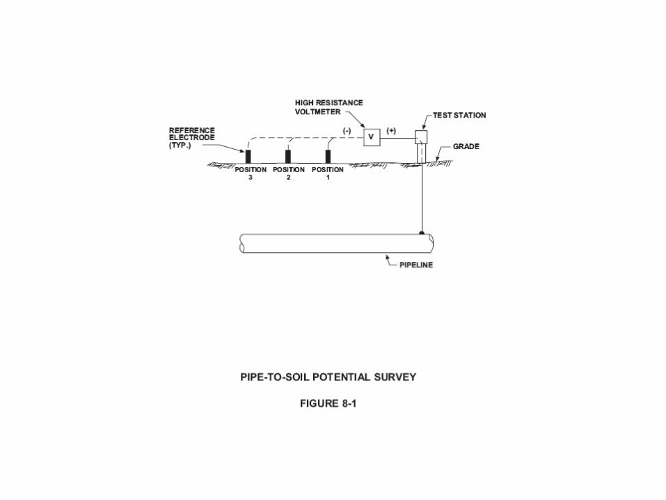
• Reference electrode (Figure 8-1)
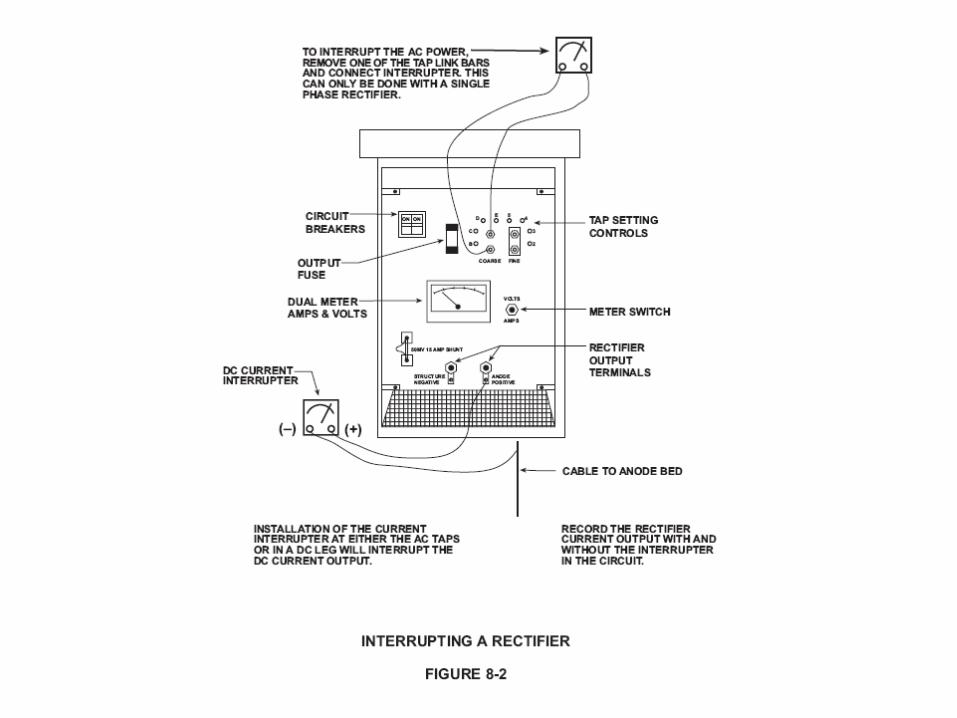
• Current Interrupter (Figure 8-2)
Pipe to Soil Potentials Surveys
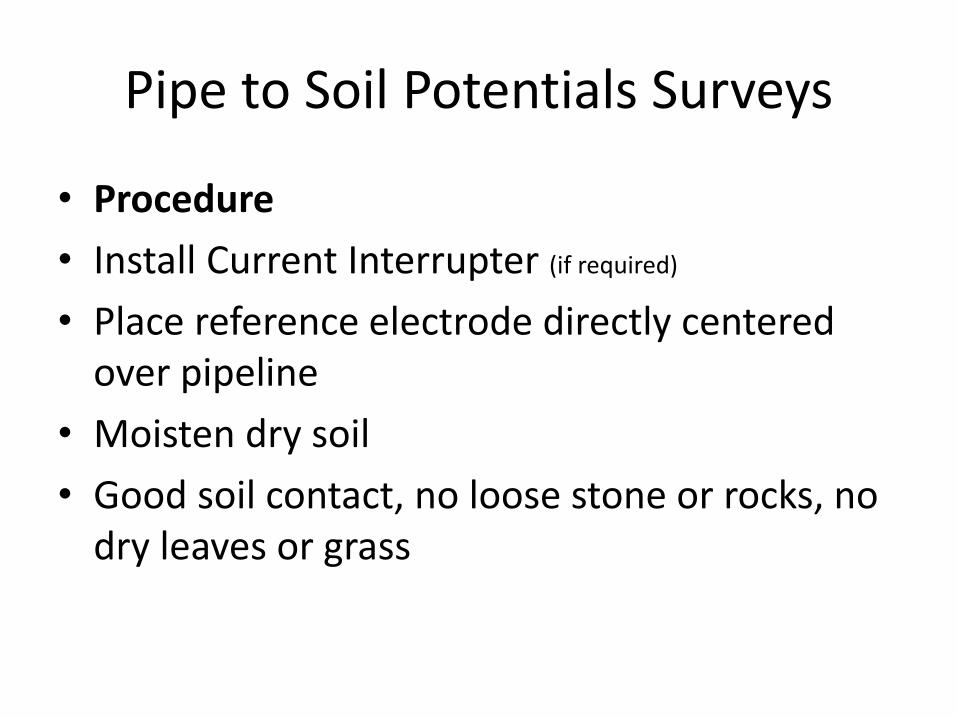
• Procedure
• Install Current Interrupter (if required)
• Place reference electrode directly centered over pipeline
• Moisten dry soil
• Good soil contact, no loose stone or rocks, no dry leaves or grass
Pipe to Soil Potentials Surveys
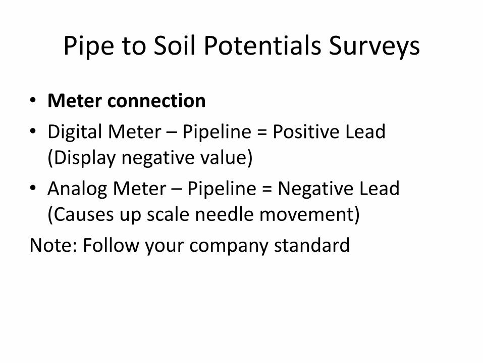
• Meter connection
• Digital Meter – Pipeline = Positive Lead (Display negative value)
• Analog Meter – Pipeline = Negative Lead (Causes up scale needle movement)
Note: Follow your company standard
Pipe to Soil Potentials Surveys
• Calculating Ground Voltage Coupling to determine increase of current to meet a criteria
Ground Voltage Coupling
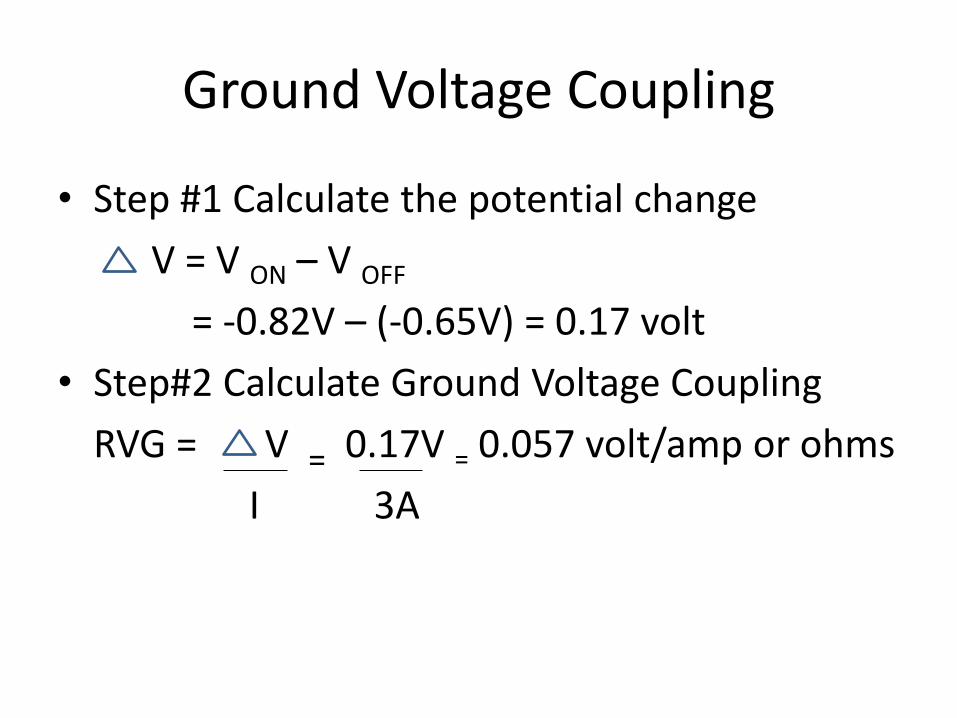
• Step #1 Calculate the potential change
V = V ON – V OFF
= -0.82V – (-0.65V) = 0.17 volt
• Step#2 Calculate Ground Voltage Coupling
RVG = V = 0.17V = 0.057 volt/amp or ohms
I 3A
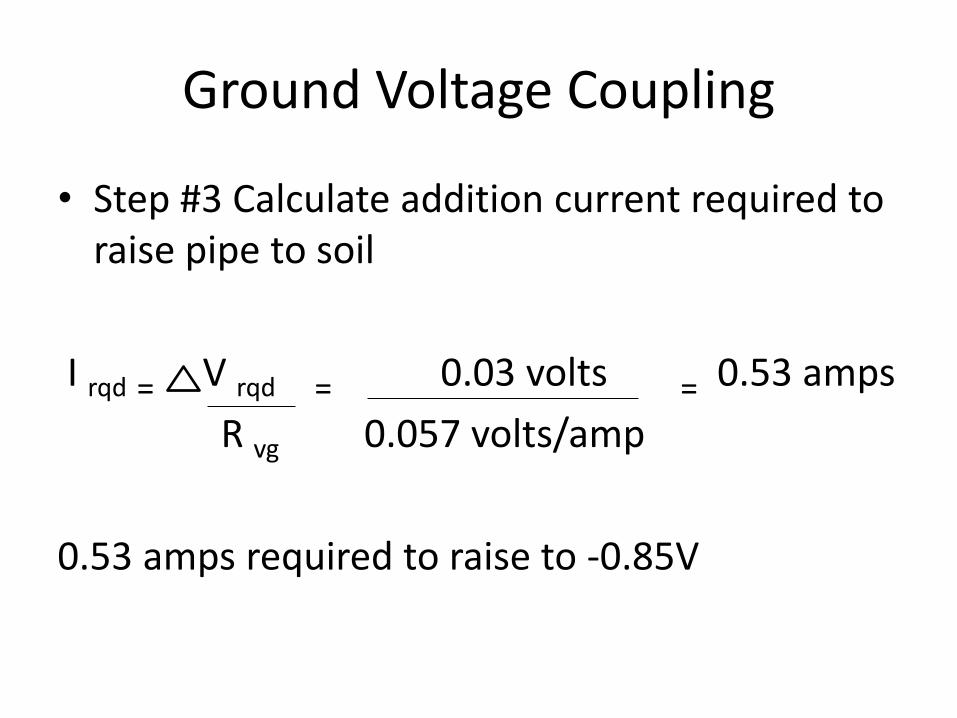
Ground Voltage Coupling
• Step #3 Calculate addition current required to raise pipe to soil
I rqd = V rqd = 0.03 volts = 0.53 amps
R vg 0.057 volts/amp
0.53 amps required to raise to -0.85V
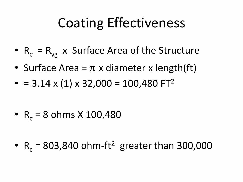
Coating Effectiveness
• Rc = Rvg x Surface Area of the Structure
• Surface Area = p x diameter x length(ft)
• = 3.14 x (1) x 32,000 = 100,480 FT2
• Rc = 8 ohms X 100,480
• Rc = 803,840 ohm-ft2 greater than 300,000
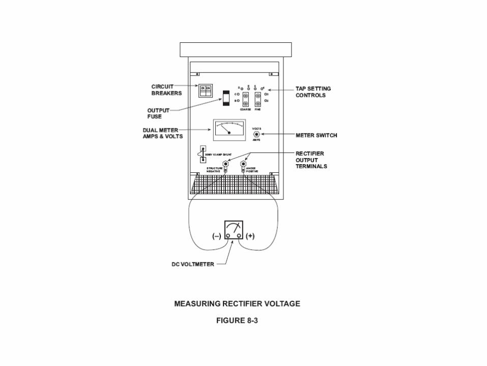
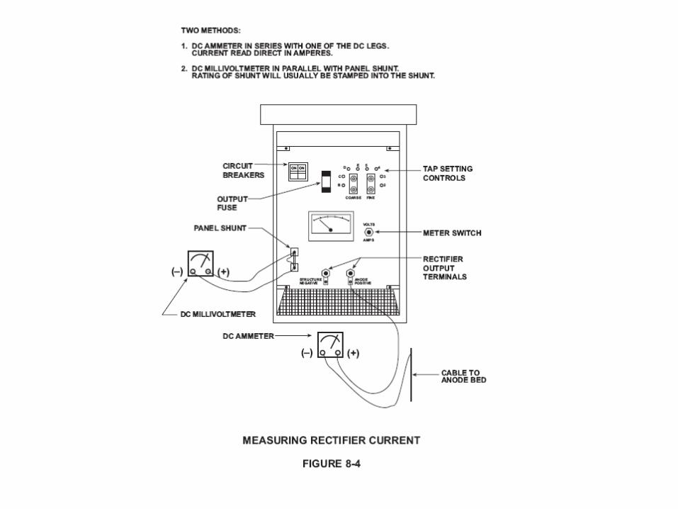
Rectifier Inspection
• Measure DC voltage, current and Pipe to Soil potential (Figures 8-3, 8-4)
• Collect information to calculate efficiency
• Visually inspect for burnt components, loose wires
• Visually inspect and clean if necessary top and bottom screens
• Oil bath units inspect oil level and fill if necessary
• Calculate anode bed resistance
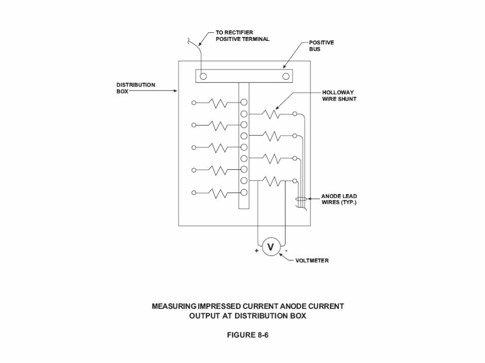
Impressed Current Junction Box
• Measure current output to each anode and compare with previous measurements(Fig 8-6)
Bonds – Critical and Non Critical
• Measure Pipe to Soils of each structure bonded and unbonded
• Measure current flow thru bond and identify current flow direction
Use your company standard for meter connection
Casings
• Measure resistance between casing and carrier
• Periodically perform Casing Short Test – How to set up and perform test later in chapter
Dynamic Stray Current Areas
• Verify that bonds, switches, or other corrective methods are functional
• Periodically set data recording instruments to measure pipe to soil and current flow
Isolation Joints
• Verify that isolation joints are functioning properly
• Inspect the spark gaps and grounding cells function properly
• Inspect jumpers installed across isolation joints for continuity
Any Other Cathodic Protection Devices
• Inspect and test all other devices for proper function
• Remote monitoring devices
• Solar cells
• Generators
Records and Data Sheets
• Date and Time
• Technician or Technicians
• Weather Conditions
• Location of test or inspection
• Instruments – serial and model numbers
• Polarity (+/-)
• Meter scale if non auto ranging
Records and Data Sheets
• Conditions when data was taken:
– Rectifer on/off
– Bonds in/out
– Current source
– Type of reference cell and location
– Soil conditions
– Any unusual conditions
Repair or Replacements
• Coatings
• Rectifiers
• Impressed Current Anode Beds
• Galvanic Anodes
• Test Stations
Coatings
• Recoating is expensive
• May be necessary when cathodic protection requirements become to great
• Recoat material should be selected to with stand environment of pipeline
• Installed to company or manufacturers procedures – Properly trained installers
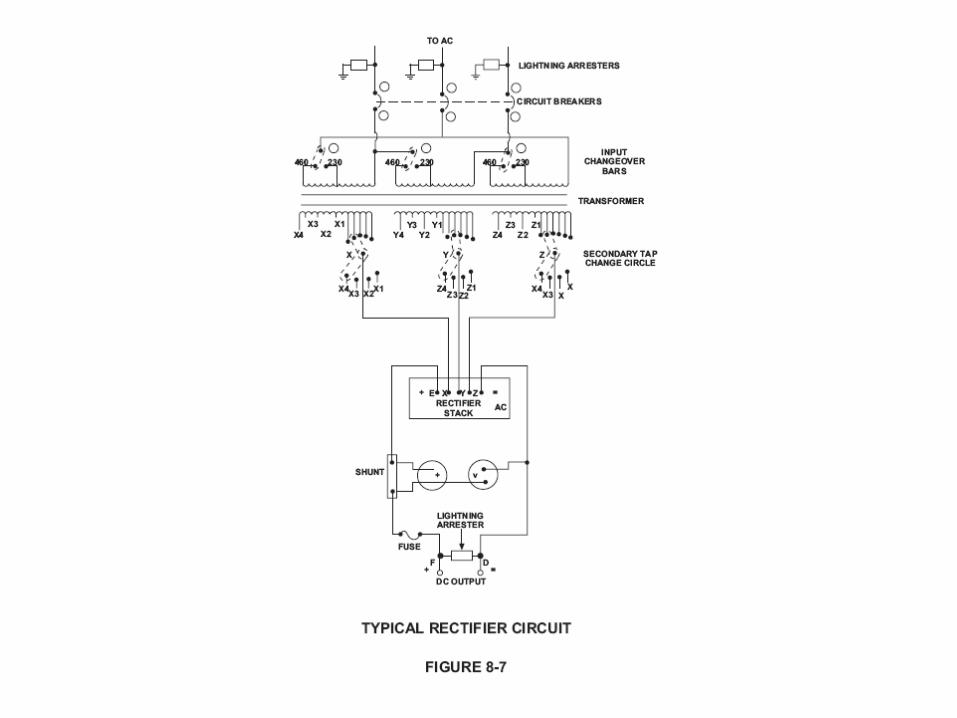
Rectifiers (Figure 8-7)
• Troubleshooting
• READ MANUAL and SCHEMATIC
• Turn off when possible to troubleshoot
• Check fuses and circuit breaks first
• Use senses: touch, smell and sight
• Start with AC input side work to DC output
• Take specific class for troubleshooting
Impressed Current Anode Beds
• Damaged or broken cable
• Damaged anodes
• Consumed anodes
• Improper installation of splices
• Improper installation of splice isolation kits
Galvanic Anodes
• Broken or damaged wires
• Depleted anodes
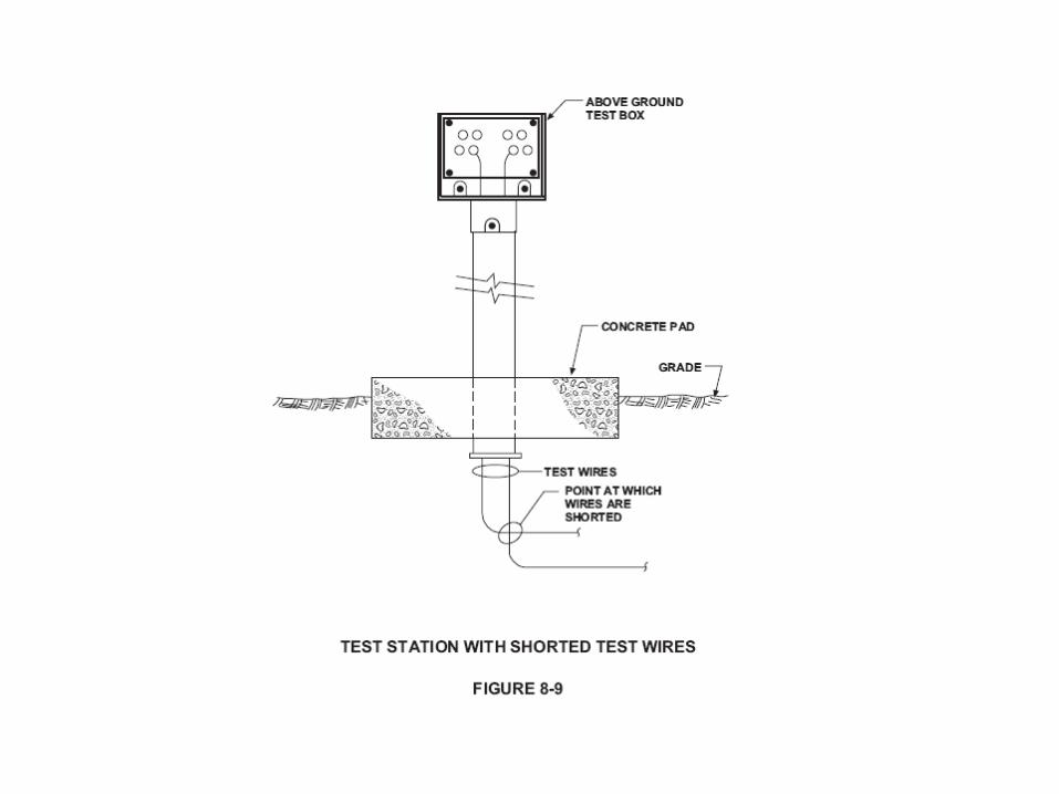
Test Stations
• High resistance connections
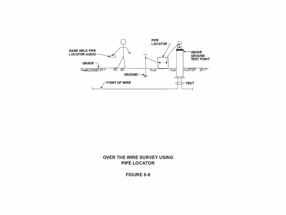
• Broken wires – Use locator to perform “over wire survey” to find break (Figure 8-8)
• Measure resistance of wires, to calculate resistance/foot to determine break location (Figure 8-9)
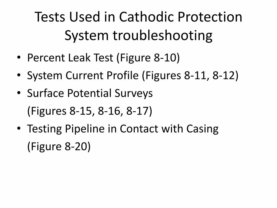
Tests Used in Cathodic Protection System troubleshooting
• Percent Leak Test (Figure 8-10)
• System Current Profile (Figures 8-11, 8-12)
• Surface Potential Surveys
(Figures 8-15, 8-16, 8-17)
• Testing Pipeline in Contact with Casing
(Figure 8-20)
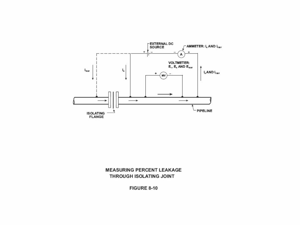
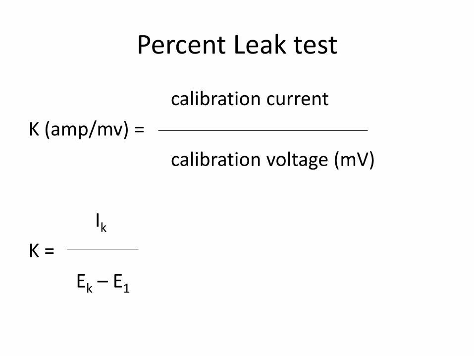
Percent Leak test
calibration current
K (amp/mv) =
calibration voltage (mV)
Ik
K =
Ek – E1
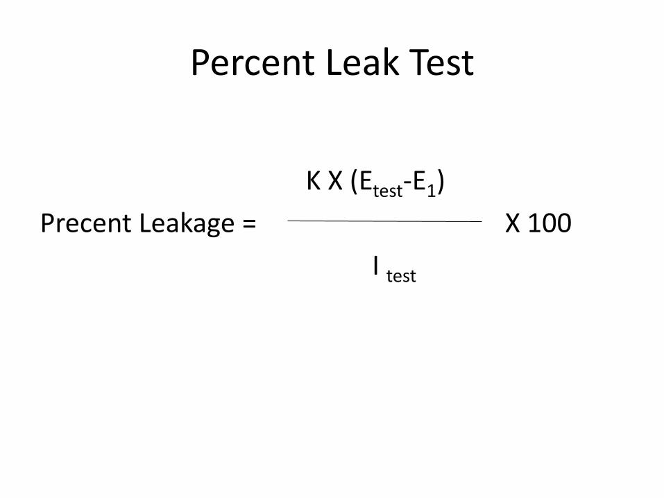
Percent Leak Test
K X (Etest-E1)
Precent Leakage = X 100
I test
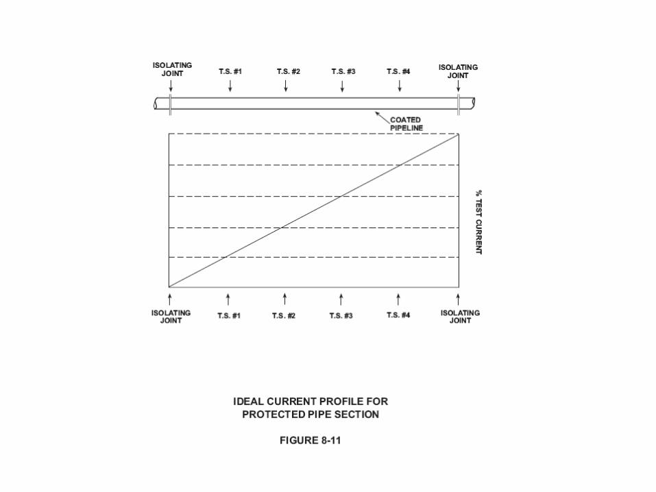
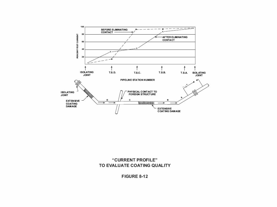
System Current Profile (Fig 8-11 & Fig 8-12)
• Using millivolt drop measurements
• Plot of test station location vs percent test current
• Problem areas are located and futher test should be preformed
• Other tests: short locating, surface potential surveys, more extensive millivolt drop tests, and current flow direction tests
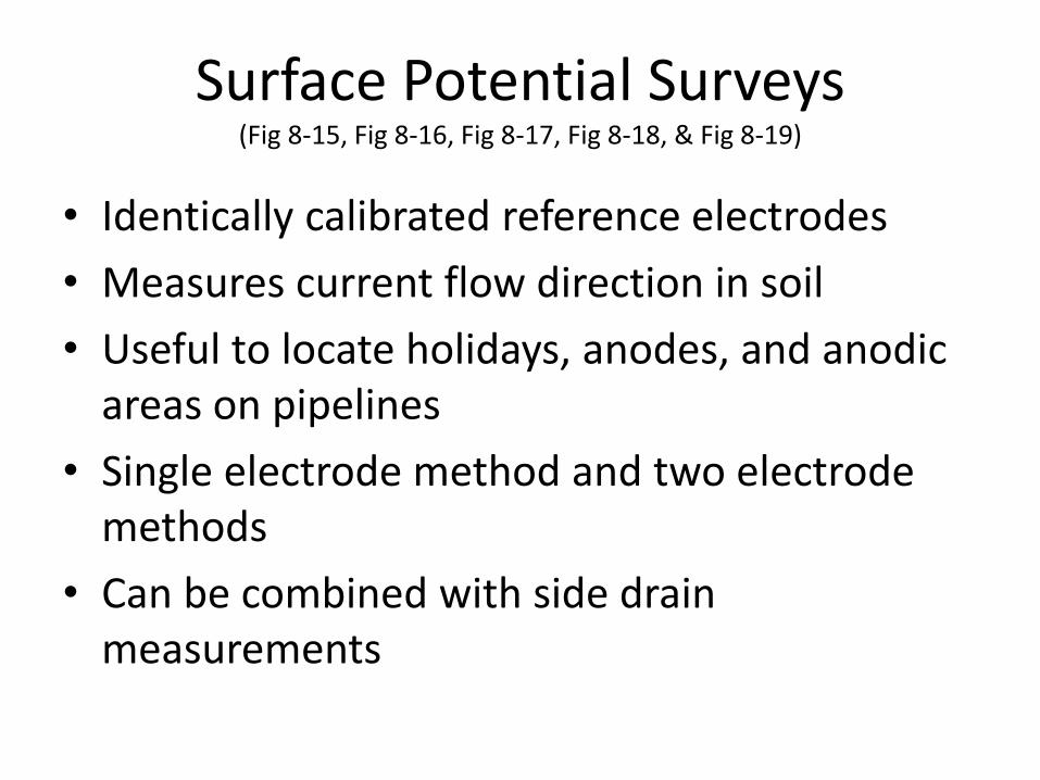
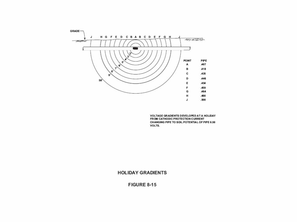
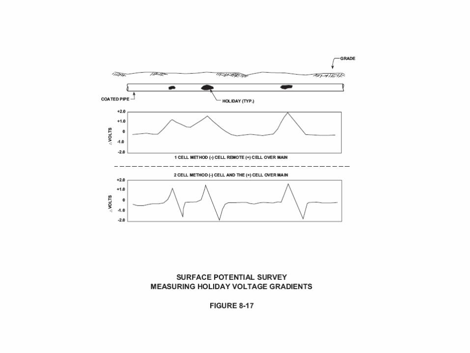
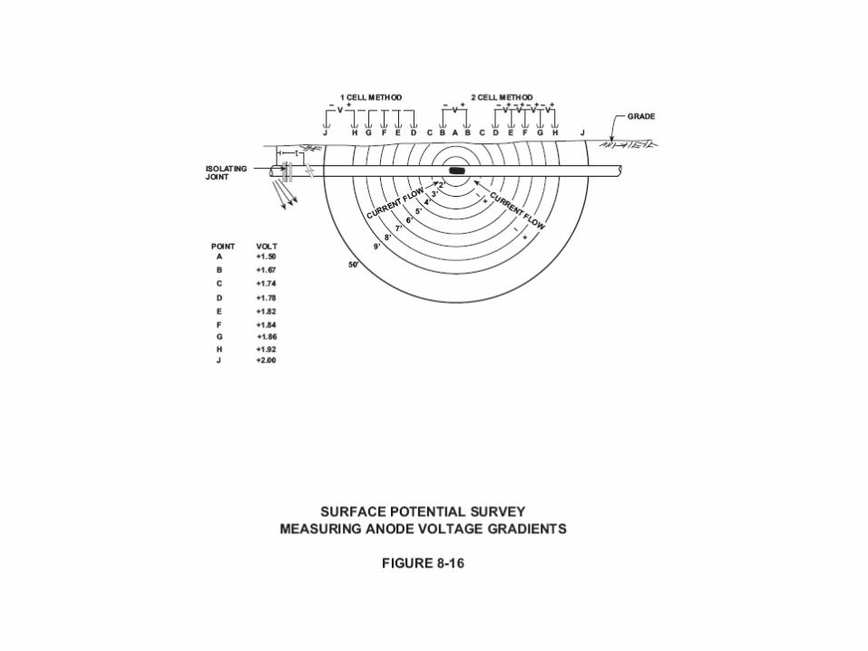
Surface Potential Surveys (Fig 8-15, Fig 8-16, Fig 8-17, Fig 8-18, & Fig 8-19)
• Identically calibrated reference electrodes
• Measures current flow direction in soil
• Useful to locate holidays, anodes, and anodic areas on pipelines
• Single electrode method and two electrode methods
• Can be combined with side drain measurements

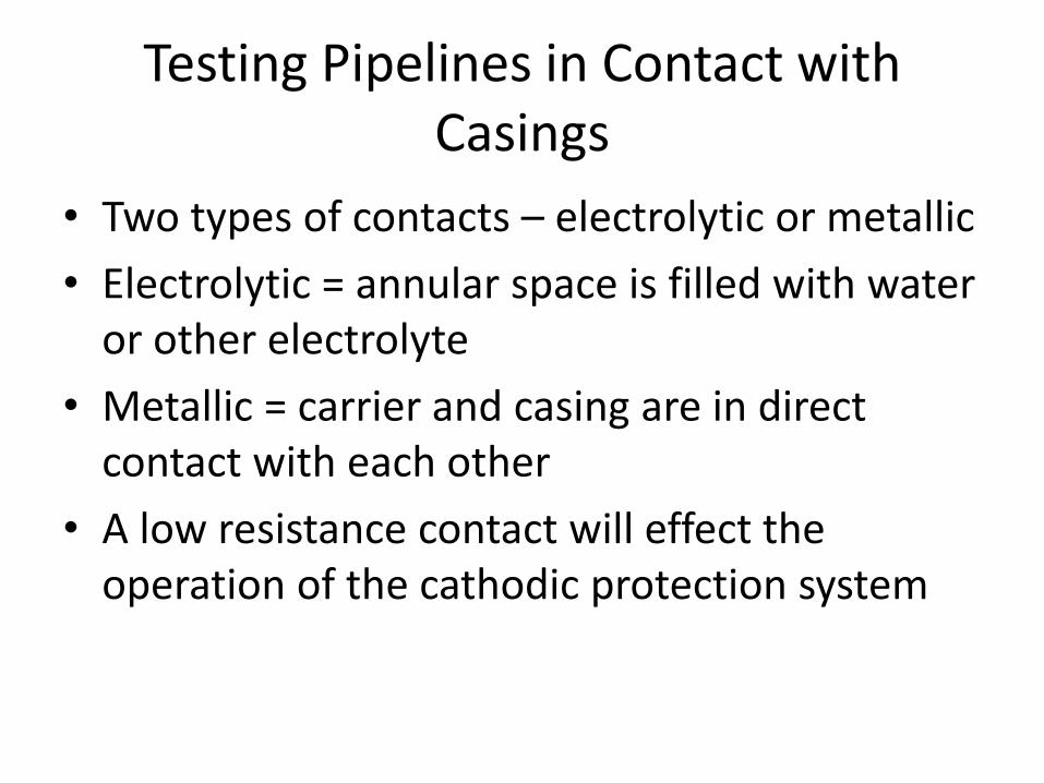
Testing Pipelines in Contact with Casings
• Two types of contacts – electrolytic or metallic
• Electrolytic = annular space is filled with water or other electrolyte
• Metallic = carrier and casing are in direct contact with each other
• A low resistance contact will effect the operation of the cathodic protection system
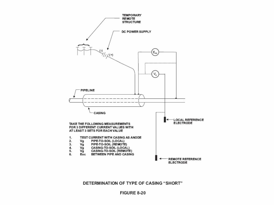
Testing Pipelines in Contact with Casings
• Casing short test (Fig 8-20)


![cathodic protection in practise · 2 [CATHODIC PROTECTION/BM] CATHODIC PROTECTION P E FRANCIS 1 INTRODUCTION The first practical use of cathodic protection is generally credited to](https://static.documents.pub/doc/80x56/5ace93c87f8b9ae2138b87e4/cathodic-protection-in-cathodic-protectionbm-cathodic-protection-p-e-francis.jpg)


