Chapter 8 – Electrical Power Systems Table of Contents CHAPTER 8 ELECTRICAL POWER SYSTEMS TABLE OF CONTENTS Section Title Page SHINE Medical Technologies 8-i Rev. 0 8a2 IRRADIATION FACILITY ELECTRICAL POWER SYSTEMS .......................... 8a2.1-1 8a2.1 NORMAL ELECTRICAL POWER SUPPLY SYSTEM ..................................... 8a2.1-1 8a2.1.1 DESIGN BASIS ............................................................................. 8a2.1-1 8a2.1.2 OFF-SITE POWER SUPPLY DESCRIPTION ............................... 8a2.1-2 8a2.1.3 NORMAL ELECTRICAL POWER SUPPLY SYSTEM DESCRIPTION .............................................................................. 8a2.1-2 8a2.1.4 GROUNDING AND LIGHTNING PROTECTION .......................... 8a2.1-3 8a2.1.5 RACEWAY AND CABLE ROUTING ............................................. 8a2.1-3 8a2.1.6 LOSS OF OFF-SITE POWER ....................................................... 8a2.1-4 8a2.1.7 TECHNICAL SPECIFICATIONS .................................................... 8a2.1-5 8a2.2 EMERGENCY ELECTRICAL POWER SYSTEMS .......................................... 8a2.2-1 8a2.2.1 UNINTERRUPTIBLE ELECTRICAL POWER SUPPLY SYSTEM DESIGN BASIS .............................................................. 8a2.2-1 8a2.2.2 UNINTERRUPTIBLE ELECTRICAL POWER SUPPLY SYSTEM CODES AND STANDARDS ........................................... 8a2.2-2 8a2.2.3 UNINTERRUPTIBLE ELECTRICAL POWER SUPPLY SYSTEM DESCRIPTION ............................................................... 8a2.2-2 8a2.2.4 STANDBY GENERATOR SYSTEM DESIGN BASIS ..................... 8a2.2-4 8a2.2.5 STANDBY GENERATOR SYSTEM CODES AND STANDARDS ................................................................................. 8a2.2-5 8a2.2.6 STANDBY GENERATOR SYSTEM DESCRIPTION ..................... 8a2.2-5 8a2.2.7 EMERGENCY ELECTRICAL POWER SYSTEM OPERATION ..... 8a2.2-5 8a2.2.8 TECHNICAL SPECIFICATIONS .................................................... 8a2.2-6 8a2.3 REFERENCES ................................................................................................. 8a2.3-1
Transcript
Chapter 8 – Electrical Power Systems Table of Contents
CHAPTER 8
ELECTRICAL POWER SYSTEMS
TABLE OF CONTENTS
Section Title Page
SHINE Medical Technologies 8-i Rev. 0
8a2 IRRADIATION FACILITY ELECTRICAL POWER SYSTEMS .......................... 8a2.1-1
8a2.1 NORMAL ELECTRICAL POWER SUPPLY SYSTEM ..................................... 8a2.1-1
Chapter 8 – Electrical Power Systems Table of Contents
CHAPTER 8
ELECTRICAL POWER SYSTEMS
TABLE OF CONTENTS
Section Title Page
SHINE Medical Technologies 8-ii Rev. 0
8b RADIOISOTOPE PRODUCTION FACILITY ELECTRICAL POWER SYSTEMS .......................................................................................................... 8b.1-1
8b.1 NORMAL ELECTRICAL POWER SYSTEMS .................................................... 8b.1-1
8b.2 EMERGENCY ELECTRICAL POWER SYSTEMS ............................................ 8b.2-1
Chapter 8 – Electrical Power Systems List of Tables
LIST OF TABLES
Number Title
SHINE Medical Technologies 8-iii Rev. 0
8a2.2-1 UPSS Load List
8a2.2-2 UPSS Battery Sizing
Chapter 8 – Electrical Power Systems List of Figures
LIST OF FIGURES
Number Title
SHINE Medical Technologies 8-iv Rev. 0
8a2.1-1 Electrical Distribution System (Simplified)
8a2.2-1 Uninterruptible Power Supply System
Chapter 8 – Electrical Power Systems Acronyms and Abbreviations
ACRONYMS AND ABBREVIATIONS
Acronym/Abbreviation Definition
SHINE Medical Technologies 8-v Rev. 0
AC alternating current
BT bus train
CAAS criticality accident alarm system
CAMS continuous air monitoring system
DC direct current
EMI electromagnetic interference
ESFAS engineered safety features actuation system
FDCS facility data and communications system
FFPS facility fire detection and suppression
FVZ4 facility ventilation zone 4
GBSS glovebox stripper system
HCFD hot cell fire detection and suppression system
HVAC heating, ventilation, and air conditioning
Hz hertz
IEEE Institute of Electrical and Electronics Engineers
Chapter 8 – Electrical Power Systems Acronyms and Abbreviations
ACRONYMS AND ABBREVIATIONS
Acronym/Abbreviation Definition
SHINE Medical Technologies 8-vi Rev. 0
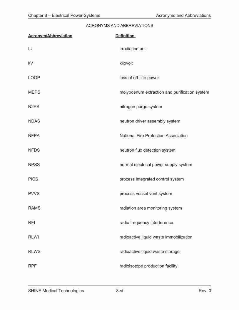
IU irradiation unit
kV kilovolt
LOOP loss of off-site power
MEPS molybdenum extraction and purification system
N2PS nitrogen purge system
NDAS neutron driver assembly system
NFPA National Fire Protection Association
NFDS neutron flux detection system
NPSS normal electrical power supply system
PICS process integrated control system
PVVS process vessel vent system
RAMS radiation area monitoring system
RFI radio frequency interference
RLWI radioactive liquid waste immobilization
RLWS radioactive liquid waste storage
RPF radioisotope production facility
Chapter 8 – Electrical Power Systems Acronyms and Abbreviations
ACRONYMS AND ABBREVIATIONS
Acronym/Abbreviation Definition
SHINE Medical Technologies 8-vii Rev. 0
RVZ1 radiological ventilation zone 1
RVZ1e radiological ventilation zone 1 exhaust subsystem
RVZ2 radiological ventilation zone 2
RVZ2e radiological ventilation zone 2 exhaust subsystem
RVZ2s radiological ventilation zone 2 supply subsystem
SGS standby generator system
SRM stack release monitor
SRMS stack release monitor system
TPS tritium purification system
TOGS TSV off-gas system
TRPS TSV reactivity protection system
TSV target solution vessel
UP utility power
UPSS uninterruptible electrical power supply system
Chapter 8 – Electrical Power Systems Acronyms and Abbreviations
ACRONYMS AND ABBREVIATIONS
Acronym/Abbreviation Definition
SHINE Medical Technologies 8-viii Rev. 0
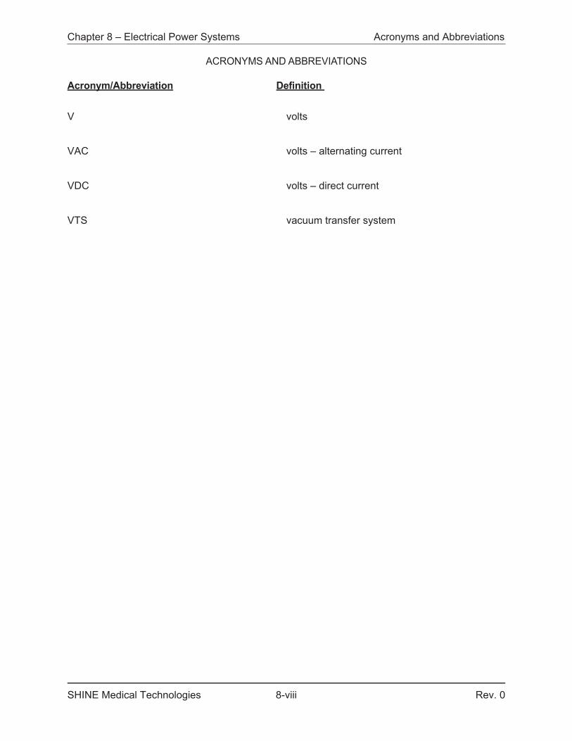
V volts
VAC volts – alternating current
VDC volts – direct current
VTS vacuum transfer system
Chapter 8 – Electrical Power Systems Normal Electrical Power SUPPLY System
SHINE Medical Technologies 8a2.1-1 Rev. 0
8a2 IRRADIATION FACILITY ELECTRICAL POWER SYSTEMS
8a2.1 NORMAL ELECTRICAL POWER SUPPLY SYSTEM
A single overall electrical power system serves the main production facility, including both the irradiation facility and the radioisotope production facility, as well as the site and support buildings. The normal electrical power supply system (NPSS) for the SHINE facility consists of the normal power service entrances from the electric utility and a distribution system providing two utilization voltages, 480Y/277 and 208Y/120 volts alternating current (VAC), 3-phase, 60 hertz. Grounding and lightning protection is provided.
The NPSS receives off-site power service from the local utility, Alliant Energy, at 480Y/277 VAC in two separate feeds. Portions of the NPSS that comprise the emergency electrical power system can also receive power from the standby generator system (SGS). The NPSS is used for normal operation and normal shutdown of the facility.
The NPSS is sized for safe operation of the facility. The largest loads on the NPSS are the process chilled water system (PCHS), neutron driver assembly system (NDAS), and the facility chilled water system (FCHS); however, those loads are not required for safe shutdown of the facility. Refer to Section 8a2.2 for a tabulation of emergency electrical load requirements.
A simplified diagram of the overall electrical power system is provided in Figure 8a2.1-1.
8a2.1.1 DESIGN BASIS
The design of the NPSS is based on Criterion 27, Electrical power systems, and Criterion 28, Inspection and testing of electric power systems, of the SHINE design criteria. The SHINE design criteria are described in Section 3.1.
The design of the NPSS provides sufficient, reliable power to facility and site electrical equipment as required for operation of the SHINE facility and to comply with applicable codes and standards. The NPSS is designed such that it:
• Does not prevent the ability of safety-related SSCs to perform their safety functions;• Provides for the separation or isolation of safety-related circuits from nonsafety-related
circuits, including the avoidance of electromagnetic interference with safety-related instrumentation and control functions;
• Fails to a safe configuration upon a loss of off-site power (LOOP);• Provides the normal source of power supply to the safety-related electrical buses; • Provides the safety-related function of removing power from select components when
demanded by the safety-related engineered safety features actuation system (ESFAS) or target solution vessel (TSV) reactivity protection system (TRPS); and
• Is able to be inspected, tested, and maintained to meet the above design bases.
The following codes and standards are used in the design of the NPSS:
• National Fire Protection Association (NFPA) 70-2017, National Electrical Code (NFPA, 2017), as adopted by the State of Wisconsin (Chapter SPS 316 of the Wisconsin Administrative Code, Electrical)
Chapter 8 – Electrical Power Systems Normal Electrical Power SUPPLY System
SHINE Medical Technologies 8a2.1-2 Rev. 0
• Institute of Electrical and Electronics Engineers (IEEE) 384-2008, Standard Criteria for Independence of Class 1E Equipment and Circuits (IEEE, 2008), invoked for isolation and separation of nonsafety-related circuits from safety-related circuits, as described in Subsections 8a2.1.3 and 8a2.1.5.
8a2.1.2 OFF-SITE POWER SUPPLY DESCRIPTION
The SHINE facility is connected to a single power circuit from the off-site transmission electric network. The power circuit is shared with other utility customers. This power circuit feeds two local outdoor 12.47 kilovolt (kV) - 480Y/277 VAC 3-phase transformers. The 12.47 kV feeder originates from the Alliant Energy Tripp Road substation, about 2.8 circuit miles from the SHINE facility.
Each of the two transformers is connected to one of the SHINE facility's two main 480 VAC switchgear buses. Figure 8a2.1-1 depicts the off-site connections to the SHINE facility.
8a2.1.3 NORMAL ELECTRICAL POWER SUPPLY SYSTEM DESCRIPTION
The NPSS operates as two separate branches, each receiving utility power at 480Y/277 VAC. The branches automatically physically disconnect from the utility by opening the utility power (UP) supply breakers (UP BKR 1 and UP BKR 2) on a loss of phase, phase reversal, or sustained overvoltage or undervoltage as detected by protection relays for each utility transformer. This function is not required for safe shutdown, as described in Subsection 8a2.1.6. The two branches can be cross-connected by manually opening one of the UP breakers and manually closing both bus tie (BT) breakers (BT BKR 1 and BT BKR 2) in the event of the loss of a single utility 480Y/277 VAC feed. This cross-connection would be performed at reduced loading and administratively controlled to ensure the remaining utility feed is not overloaded.
The distribution system consists of two line-ups of 480 volts (V) switchgear, two emergency 480 V buses (that are supported by the standby generator), and isolation and cross-tie breakers. The two switchgear line-ups each feed an individual emergency bus and the single SGS switchgear. The two emergency 480 V buses are nonsafety-related, but each provides power to a safety-related uninterruptible electrical power supply system (UPSS) division via division-specific battery chargers and bypass transformers. The SGS and the UPSS are further described in Section 8a2.2.
Surge protection is provided at each electrical service entrance to limit voltage spikes and electrical noise. The electrical services are monitored for voltage, frequency, and loss of phase. When an electrical service exceeds prescribed limits, the facility is disconnected from the utility to prevent damage. Refer to Section 8a2.2 for further discussion of facility response to transient events.
The NPSS complies with NFPA 70 (NFPA, 2017), as adopted by the State of Wisconsin (Chapter SPS 316 of the Wisconsin Administrative Code, Electrical); with Sections 6.1.2.1, 6.1.2.2, and 6.1.2.3 of IEEE 384 (IEEE, 2008) for isolation; and with Section 5.1.1.2, Table 1 of Section 5.1.3.3, and Table 2 of Section 5.1.4 of IEEE 384 (IEEE, 2008) for physical separation between nonsafety-related circuits and safety-related circuits.
Chapter 8 – Electrical Power Systems Normal Electrical Power SUPPLY System
SHINE Medical Technologies 8a2.1-3 Rev. 0
The NPSS contains the following safety-related equipment:
• Two undervoltage trip enclosed breakers are provided for each instance of the NDAS to provide the redundant ability to disconnect power.
• Two undervoltage trip enclosed breakers per vacuum pump to provide the redundant ability to disconnect power from each (of three) vacuum pump in the vacuum transfer system (VTS).
• Two undervoltage trip enclosed breakers per extraction feed pump to provide the redundant ability to disconnect power from each (of three) extraction feed pumps in the molybdenum extraction and purification system (MEPS).
• Two undervoltage trip enclosed breakers providing the redundant ability to disconnect power from the radiological ventilation zone 1 (RVZ1) exhaust fans, radiological ventilation zone 2 (RVZ2) exhaust fans and RVZ2 supply air handling units.
8a2.1.4 GROUNDING AND LIGHTNING PROTECTION
Equipment ground conductors, driven electrodes, buried conductors, and ground bars provide a conductive connection between facility SSCs and earth. These components, when taken together, provide intentional low impedance conductive paths for facility SSCs as required to ensure personnel safety, equipment protection, proper component function, electrical noise reduction and signal integrity.
The facility grounding system complies with NFPA 70 (NFPA, 2017). The facility grounding equipment provides no safety-related function.
Lightning protection equipment provides low impedance paths to ground that minimize the effects of potential lightning strikes on personnel, equipment, and the facility structure. It provides no safety-related function.
8a2.1.5 RACEWAY AND CABLE ROUTING
There are four separation groups for cables and raceways for the SHINE facility: Group A, Group B, Group C, and Group N. Spatial separation between groups is in accordance with Section 5.1.1.2, Table 1 of Section 5.1.3.3, and Table 2 of Section 5.1.4 of IEEE 384 (IEEE, 2008).
• Separation Group A contains safety-related power circuits from UPSS Division A and safety-related control circuits from TRPS, NFDS, and ESFAS Division A.
• Separation Group B contains safety-related power circuits from UPSS Division B and safety-related control circuits from TRPS, NFDS, and ESFAS Division B.
• Separation Group C contains safety-related control circuits from TRPS and ESFAS Division C. For additional information on the Division C circuits see Section 7.2.
• Group N contains the facility nonsafety-related cables, including NPSS and SGS power circuits and process integrated control system (PICS) control circuits.
Nonsafety-related circuits are electrically isolated from safety-related circuits by isolation devices in accordance with Sections 6.1.2.1, 6.1.2.2, and 6.1.2.3 of IEEE 384 (IEEE, 2008). See Chapter 7 for additional discussion of safety-related control systems.
Chapter 8 – Electrical Power Systems Normal Electrical Power SUPPLY System
SHINE Medical Technologies 8a2.1-4 Rev. 0
8a2.1.6 LOSS OF OFF-SITE POWER
A LOOP is defined as zero voltage/power supplied by the utility, loss of a phase, phase reversal, sustained overvoltage or sustained undervoltage. When there is loss of phase, phase reversal, sustained overvoltage or sustained undervoltage, the facility automatically disconnects from the utility. For the plant equipment, all the scenarios result in zero voltage/power supplied by the utility.
IUs in Mode 0 (Solution Removed) are unaffected by the LOOP - the neutron driver is not operating and target solution is not present in the IU.
TSV filling operations for IUs in Mode 1 (Filling) will be stopped via the loss of power to the VTS, which causes the VTS vacuum pumps to shut down and the VTS vacuum breaker valve to open. Neutron flux monitoring and safety-related protection systems will remain operational, powered via the UPSS (see Section 8a2.2). If the SGS is available, the SGS will auto start to provide backup power to the TSV off-gas system (TOGS), allowing the TOGS to continue to operate and mitigate hydrogen generated by radiolysis from decay radiation in the target solution. If the SGS is not available, the TOGS will continue to operate for five minutes, powered by the UPSS. Three minutes after loss of external power to the UPSS, before the TOGS blowers are unloaded from the UPSS, TRPS will initiate an IU Cell Nitrogen Purge, and the nitrogen purge system (N2PS) will inject nitrogen into the TSV dump tank to provide hydrogen control in the IU. The PCLS pumps are not powered by the UPSS or SGS; therefore, PCLS flow to the TSV will be lost. Loss of PCLS flow starts a three minute timer. If PCLS flow is not restored within the three minute duration, TRPS will initiate an IU Cell Safety Actuation, resulting in the TSV dump valves opening and the target solution draining from the TSV to the TSV dump tank. Once in the TSV dump tank, the decay heat is passively removed from the target solution via natural convection to the light water pool. See Section 7.4 for additional information about the TRPS. See Section 4a2.4 for additional discussion of the light water pool.
Each operating neutron driver for an IU in Mode 2 (Irradiation) will shut down due to loss of power to the driver. Shutdown of the neutron driver will result in lowered neutron flux within the IU. This causes a Driver Dropout actuation on low neutron flux which results in opening the driver high voltage power supply breakers. Similar to the effect of a LOOP during Mode 1 operation, the target solution will be drained from the TSV to the TSV dump tank after a three minute delay via an IU Cell Safety Actuation occurs unless off-site power is restored. Also similar to Mode 1, an IU Cell Nitrogen Purge will occur after three minutes if the NPSS or SGS is not available to power the TOGS.
IUs in Mode 3 (Post-Irradiation) will be provided hydrogen mitigation by TOGS, which is powered by the UPSS for five minutes if the SGS is unavailable. TRPS initiates an IU Cell Nitrogen Purge after three minutes if power from the NPSS or SGS is not restored. If the SGS is available, these units are unaffected by a LOOP because active cooling is not provided in Mode 3.
Finally, with the exception of target solution transfer operations, which will be stopped via the loss of VTS, IUs in Mode 4 (Transfer to RPF) are affected by the LOOP identically to IUs in Mode 3.
Chapter 8 – Electrical Power Systems Normal Electrical Power SUPPLY System
SHINE Medical Technologies 8a2.1-5 Rev. 0
Additionally, a LOOP will result in the following conditions for the facility:
• If the SGS does not start, the process vessel vent system (PVVS) blowers shut down immediately and the TOGS blowers shut down after a five minute delay. N2PS valves open on loss of PVVS to allow the introduction of nitrogen sweep gas into process tanks in the RPF containing radioactive liquid to dilute hydrogen gas generated by radiolysis. N2PS valves open after a three minute delay to allow the introduction of nitrogen sweep gas into TSV dump tanks in the IF, preventing the accumulation of hydrogen beyond allowable limits.
• Heating, ventilation, and air conditioning (HVAC) systems shut down and ventilation dampers with a confinement function fail closed to ensure the confinement function is provided, and preventing uncontrolled releases of radioactive material.
• Other systems throughout the facility, including tritium purification system (TPS), VTS, and all three cooling water systems shut down and isolation valves with a confinement function fail closed.
• Controlled releases of radioactive material continue using N2PS sweep gas through the carbon delay beds, which is monitored by the carbon delay bed effluent monitor. The carbon delay bed effluent monitor is powered by the UPSS with backup power from the SGS.
• The radioactive liquid waste storage (RLWS) and the radioactive liquid waste immobilization (RLWI) systems fail safe upon a LOOP.
8a2.1.7 TECHNICAL SPECIFICATIONS
Certain material in this section provides information that is used in the technical specifications. This includes limiting conditions for operation, setpoints, design features, and means for accomplishing surveillances. In addition, significant material is also applicable to, and may be used for the bases that are described in the technical specifications.
Chapter 8 – Electrical Power Systems Normal Electrical Power Systems
SHINE Medical Technologies 8a2.1-6 Rev. 0
Figure 8a2.1-1 – Electrical Distribution System (Simplified)
UP BKR 1 UP BKR 2
UPXFMR 1
UPXFMR 2
NV BKR 1 NV BKR 2
480V SWGR A 480V SWGR BBT BKR 1 BT BKR 2
SGS BKR 1 SGS BKR 2
EMERG. BUS-A
EMERG. BUS-B
EMERG. BKR 1 EMERG. BKR 2
SG
SGISOBKR
SGS SWGR
BATTCHGR BKR 1
BATTCHGR BKR 2
VRXFMRBKR 1
VRXFMRBKR 2
125VDC UPSS A 125VDC UPSS B
BatteryA
BATTBKR 1
UPSBKR 1
BatteryB
BATTBKR 2
UPSBKR 2
AC UPSS A AC UPSS B
AC Loads
NDAS
AC Loads
DC Loads DC Loads
AC Loads AC Loads
Safety-Related Equipment
Alliant 12.47kVUtility Power Supply
12.47kVAC480Y/277VAC
125VDC
208Y/120VAC
BATT CHGR A BATT CHGR BBYPASSXFMR B
BYPASSXFMR A
UPSS
NPSS Nonsafety-Related
EquipmentNEC 700 NEC 701 NEC 702
SAFETYRELATED
SAFETYRELATED
NDAS
SAFETYRELATED
SAFETYRELATED
TYP. 4TYP. 4
BYPASSXFMR
SEC. BRKR
BYPASSXFMR
SEC. BKR
Chapter 8 – Electrical Power Systems Emergency Electrical Power Systems
SHINE Medical Technologies 8a2.2-1 Rev. 0
8a2.2 EMERGENCY ELECTRICAL POWER SYSTEMS
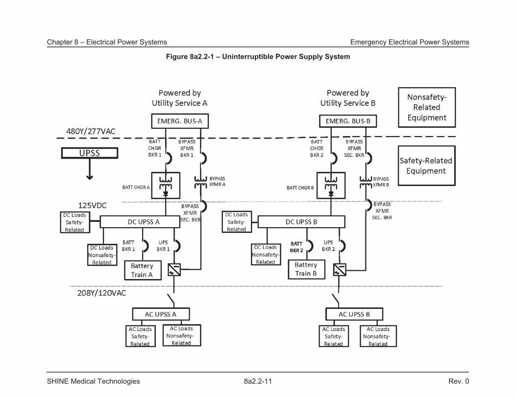
The emergency electrical power systems for the SHINE facility consist of the safety-related uninterruptible electrical power supply system (UPSS), the nonsafety-related standby generator system (SGS), and nonsafety-related local power supplies and unit batteries. The UPSS provides reliable power for the safety-related equipment required to prevent or mitigate the consequences of design basis events. The UPSS consists of a 125-volt direct current (VDC) battery subsystem, inverters, bypass transformers, distribution panels, and other distribution equipment necessary to feed safety-related alternating current (AC) and direct current (DC) loads and select nonsafety-related AC and DC loads.
The SGS consists of a single natural gas-driven generator and associated breakers and distribution equipment. The SGS provides an alternate source of power for UPSS loads. Additionally, emergency power is provided by the SGS for facility physical security control systems and information and communications systems. Unit batteries provide power for egress and exit lights, switchgear control (station control batteries), and nonsafety-related local uninterruptible power supplies which provide back-up power for communications, data systems, and nonsafety-related control systems. The SGS provides an alternate source of power for the unit batteries and their associated loads.
Nonsafety-related local power supplies for the process integrated control system (PICS) and the facility data and communications systems (FDCS) are described in Sections 7.6 and 9a2.4, respectively.
8a2.2.1 UNINTERRUPTIBLE ELECTRICAL POWER SUPPLY SYSTEM DESIGN BASIS
The design of the UPSS is based on Criterion 27, Electrical power systems, and Criterion 28, Inspection and testing of electric power systems, of the SHINE design criteria. The SHINE design criteria are described in Section 3.1.
The purpose of the UPSS is to provide a safety-related source of power to equipment required to ensure and maintain safe facility shutdown and prevent or mitigate the consequences of design basis events.
The UPSS:
• Provides power at a sufficient capacity and capability to allow safety-related SSCs to perform their safety functions;
• Is designed, fabricated, erected, tested, operated, and maintained to quality standards commensurate with the importance of the safety functions to be performed;
• Is designed to withstand the effects of design basis natural phenomena without loss of capability to perform its safety functions;
• Is located to minimize, consistent with other safety requirements, the probability and effect of fires and explosions;
• Has sufficient independence, redundancy, and testability to perform its safety functions assuming a single failure;
• Incorporates provisions to minimize the probability of failure as a result of or coincident with the loss of power from the transmission network; and
• Permits appropriate periodic inspection and testing to assess the continuity of the system and the condition of components.
Chapter 8 – Electrical Power Systems Emergency Electrical Power Systems
SHINE Medical Technologies 8a2.2-2 Rev. 0
8a2.2.2 UNINTERRUPTIBLE ELECTRICAL POWER SUPPLY SYSTEM CODES AND STANDARDS
The UPSS is designed in accordance with the following codes and standards:
• National Fire Protection Association (NFPA) 70-2017, National Electrical Code (NFPA, 2017), as adopted by the State of Wisconsin (Chapter SPS 316 of the Wisconsin Administrative Code, Electrical)
• IEEE Standard 344 - 2004, Recommended Practice for Seismic Qualification of Class 1E Equipment for Nuclear Power Generating Systems (IEEE, 2004); invoked to meet seismic requirements, as described in Subsection 8a2.2.3
• IEEE Standard 384 - 2008, Standard Criteria for Independence of Class 1E Equipment & Circuits (IEEE, 2008); invoked for separation and isolation of safety-related and nonsafety-related cables and raceways and for associated equipment, as described in Subsection 8a2.2.3
• IEEE Standard 485 - 2010, Recommended Practice for Sizing Lead-Acid Batteries for Stationary Applications (IEEE, 2010); invoked for battery sizing of UPSS loads, as described in Subsection 8a2.2.3
8a2.2.3 UNINTERRUPTIBLE ELECTRICAL POWER SUPPLY SYSTEM DESCRIPTION
The safety-related UPSS provides a reliable source of power to the redundant divisions of AC and DC components on the safety-related power buses. Each division of the UPSS consists of a 125 VDC battery subsystem, 125 VDC to 208Y/120 volts alternating current (VAC) inverter, rectifier (battery charger), bypass transformer, static switch and a manual bypass switch, 208Y/120 VAC and 125 VDC distribution panels, and a nonsafety-related 208Y/120 VAC bus system isolated from the safety-related portion of the system by isolating fuses.
Distribution wiring from each division of the UPSS is isolated and separated from the other division per Sections 6.1.2.1, 6.1.2.2, and 6.1.2.3 of IEEE 384 (IEEE, 2008) for isolation and with Section 5.1.1.2, Table 1 of Section 5.1.3.3, and Table 2 of Section 5.1.4 of IEEE 384 (IEEE, 2008) for physical separation.
A simplified diagram of the UPSS is provided in Figure 8a2.2-1.
Each division of UPSS is normally powered by an emergency 480 VAC NPSS bus via a division-specific battery charger. The emergency 480 VAC NPSS buses can also be powered by the SGS, providing an alternate source of power to the UPSS. The SGS is described in Subsection 8a2.2.4.
The UPSS is isolated from the NPSS and SGS by isolating breakers feeding the battery chargers and the bypass transformers. These devices are identified as breakers BATT CHGR BRK 1, BATT CHGR BKR 2, BYPASS XFMR BKR 1 and BYPASS XRMR BKR 2 in Figure 8a2.2-1. The breakers monitor incoming power for voltage, phase, and frequency, and will trip when monitored variables are out of limits.
Chapter 8 – Electrical Power Systems Emergency Electrical Power Systems
SHINE Medical Technologies 8a2.2-3 Rev. 0
Each battery charger supplies power to the safety-related 125 VDC bus for its division. The loads on each DC bus consist of the following:
• Engineered safety features actuation system (ESFAS)• Target solution vessel (TSV) reactivity protection system (TRPS)• TSV off-gas system (TOGS) recombiner heaters• Nitrogen purge system (N2PS) solenoid valves• TSV dump valves
Separate feeds connected to the 125 VDC bus, isolated from the safety-related portion of the bus by isolation overcurrent devices (fuses), provide power to the following nonsafety-related load:
• TPS glovebox stripper system (GBSS) heaters
The TPS GBSS heaters are associated equipment, as defined in Section 4.5.2 of IEEE 384 (IEEE, 2008).
Each 125 VDC bus supplies power to an associated 208Y/120 VAC bus via an inverter. The two 208Y/120 VAC buses can also each receive power directly from the associated emergency 480 VAC NPSS bus through a bypass transformer. The safety-related loads on each AC bus consist of the following:
• ESFAS radiation monitors• TRPS radiation monitors• TPS GBSS tritium monitors• TPS glovebox tritium monitors• Neutron driver assembly system (NDAS) high voltage power supply breaker undervoltage
hold circuits• Vacuum transfer system (VTS) vacuum pump breaker undervoltage hold trip circuits• Molybdenum extraction and purification system (MEPS) undervoltage hold trip circuits• Radiological ventilation zone 1 (RVZ1) exhaust subsystem (RVZ1e) exhaust fans,
Radiological ventilation zone 2 (RVZ2) exhaust subsystem (RVZ2e) exhaust fans, and RVZ2 supply subsystem (RVZ2s) air handling units undervoltage hold trip circuits
• TOGS blowers• Neutron flux detection system (NFDS) power cabinets and detectors for the associated
division
Separate distribution panels connected to the 208Y/120 VAC bus, isolated from the safety-related portion of the bus by isolation overcurrent devices, provide power to nonsafety-related loads important for providing alerts to facility personnel and for monitoring the status of the facility.
These loads consist of:
• Main facility stack release monitor (SRM)• Process vessel vent system (PVVS) carbon delay bed effluent monitor • TPS GBSS blowers• Criticality accident alarm system (CAAS)
Additional details about the UPSS loads are provided in Table 8a2.2-1.
Chapter 8 – Electrical Power Systems Emergency Electrical Power Systems
SHINE Medical Technologies 8a2.2-4 Rev. 0
Upon a loss of NPSS power and unavailability of SGS power, the AC and DC UPSS buses are powered by the safety-related battery bank for each division. Each UPSS division is located in a separate fire area in the safety-related, seismic portion of the main production facility. The UPSS is required to perform its safety function before, during, and after a seismic event, and is qualified by one of the testing methods described in Chapter 8 of IEEE 344 (IEEE, 2004).
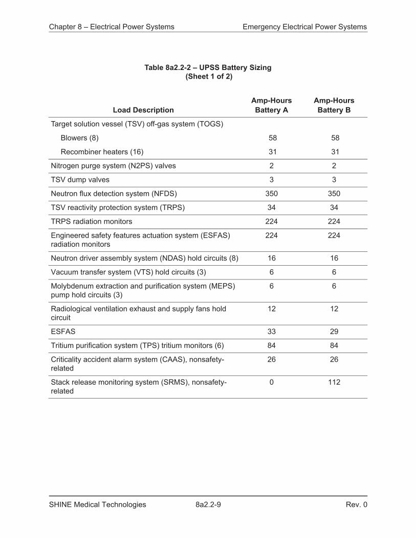
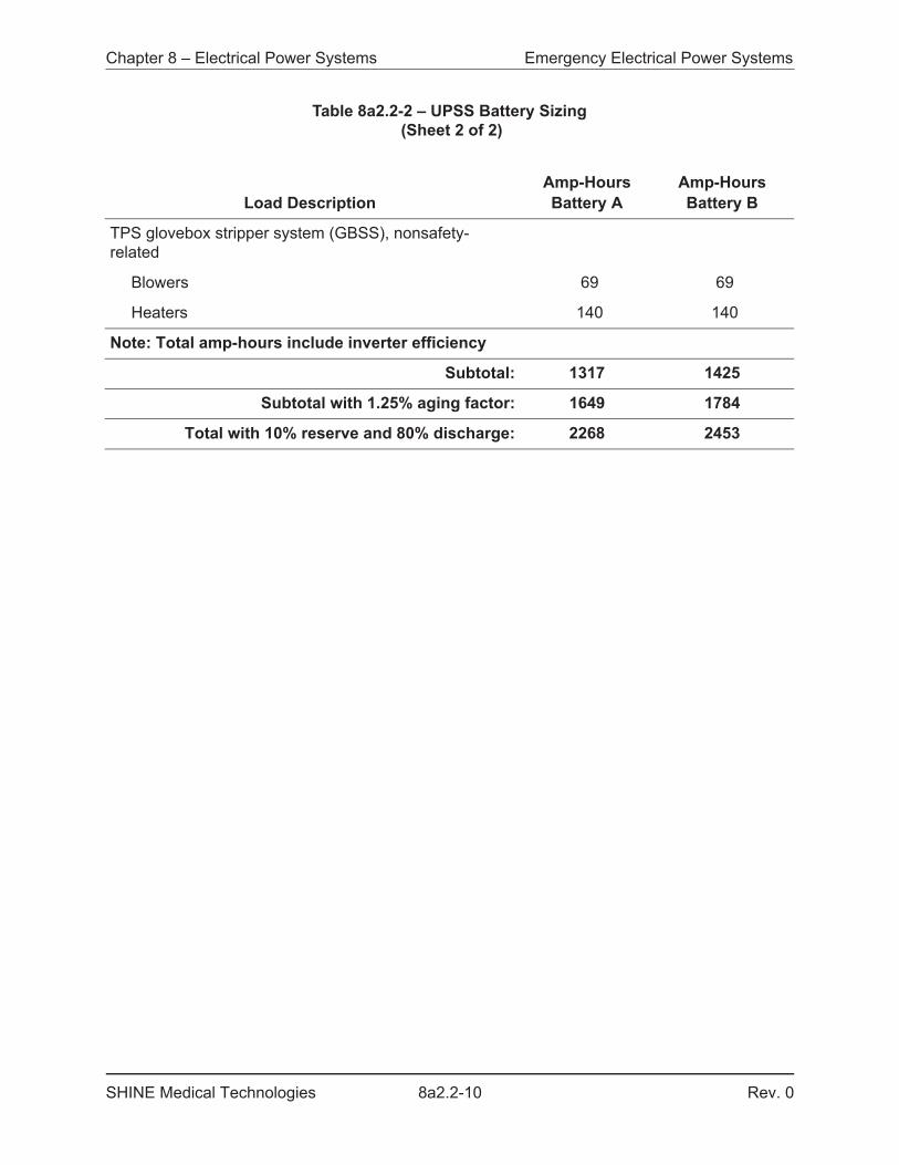
The battery sizing for the UPSS loads is shown in Table 8a2.2-2, using the sizing guidance provided in Sections 6.1.1, 6.2.1, 6.2.2, 6.2.3, 6.2.4, 6.3.2 and 6.3.3 of IEEE 485 (IEEE, 2010). Batteries are vented lead-acid. Transfer of loads from the NPSS to the UPSS is automatic and requires no control power.
The required reserve for loads is listed in Table 8a2.2-2. 15 percent of the total is reserved to accommodate variations of power during equipment procurement and an additional 10 percent is initially reserved for future needs that may be identified during the lifetime of the facility.
The run time requirements in Table 8a2.2-2 are based on:
1) Equipment required to prevent hydrogen deflagration is powered for five minutes,2) Equipment used to minimize transient effects on the facility due to short duration power
loss is powered for five minutes,3) Equipment used to provide alerts for facility personnel and monitor the status of the
facility during immediate recovery efforts is powered for two hours, or4) Defense-in-depth power for nonsafety-related equipment used to monitor and reduce the
tritium source term in the TPS glove box stripper system is powered for six hours.
The UPSS is designed and tested to be resistant to the electromagnetic interference (EMI)/radio frequency interference (RFI) environment. When equipment (e.g., portable radios) poses risks to the UPSS equipment or distribution wiring, administrative controls prevent the use of the equipment where it can adversely affect the UPSS.
8a2.2.4 STANDBY GENERATOR SYSTEM DESIGN BASIS
The design of the SGS is based on Criterion 27, Electrical power systems, and Criterion 28, Inspection and testing of electric power systems, of the SHINE design criteria. The SHINE design criteria are described in Section 3.1.
The purpose of the SGS is to provide a temporary source of nonsafety-related alternate power to the UPSS and selected additional loads for operational convenience and defense-in-depth.
The SGS:
• Will provide for the separation or isolation of safety-related circuits from nonsafety-related circuits, including the avoidance of electromagnetic interference with safety-related instrumentation and control functions;
• Will provide an alternate source of power for the safety-related electrical buses;• Will provide an alternate source of power to systems required for life-safety or important
for facility monitoring; • Will automatically start and supply loads upon a loss of off-site power; and• Permits appropriate periodic inspection and testing to assess the continuity of the system
and the condition of components.
Chapter 8 – Electrical Power Systems Emergency Electrical Power Systems
SHINE Medical Technologies 8a2.2-5 Rev. 0
8a2.2.5 STANDBY GENERATOR SYSTEM CODES AND STANDARDS
The SGS is designed in accordance with NFPA 70 - 2017, National Electrical Code (NFPA, 2017) as adopted by the State of Wisconsin (Chapter SPS 316 of the Wisconsin Administrative Code, Electrical).
8a2.2.6 STANDBY GENERATOR SYSTEM DESCRIPTION
The SGS consists of a 480Y/277 VAC, 60 Hertz (Hz) natural gas-driven generator, a 480 VAC switchgear, and two SGS cross-tie breakers to allow the SGS switchgear to be connected to either or both emergency 480 VAC NPSS buses. Upon a loss of off-site power (LOOP) (i.e., undervoltage or overvoltage sensed on utility service), the SGS automatically starts, both non-vital breakers (NV BKR 1 and NV BKR 2) automatically open, and the associated SGS cross-tie breakers (SGS BKR 1 and SGS BKR 2) automatically close to provide power to the associated emergency 480 VAC NPSS bus.
The loads supplied by the SGS include the loads supplied by the UPSS (see Table 8a2.2-1), as well as the following facility loads:
• Emergency lighting• Facility data and communications system (FDCS) equipment• Radiation area monitoring system (RAMS) detectors• Continuous air monitoring system (CAMS) detectors• Facility fire detection and suppression system (FFPS)• Hot cell fire detection and suppression system (HCFD)• PICS equipment• PVVS equipment• Switchgear station batteries (NPSS, SGS)• Facility access control system (FACS)• Facility ventilation zone 4 (FVZ4) UPSS battery room and equipment room exhaust fans• FDCS dedicated cooling systems
FDCS equipment, PICS equipment, and the FFPS contain nonsafety-related unit batteries or local uninterruptible power supplies to provide power to span the time between the LOOP event and the start of the SGS.
Emergency lighting located inside the main production facility is provided with unit batteries capable of supplying 90 minutes of illumination.
Operation of the SGS is not required for any safety function at the SHINE facility.
8a2.2.7 EMERGENCY ELECTRICAL POWER SYSTEM OPERATION
Electrical loads for the main production facility, site, and support buildings are normally supplied by the NPSS, as described in Section 8a2.1. When the NPSS is in operation, it supplies power to the UPSS battery chargers, which provide power to the loads on the 125 VDC bus and to the 208Y/120 VAC loads via the UPSS inverter. The battery charger is used to keep the battery bank fully charged and maintained at float charge.
Chapter 8 – Electrical Power Systems Emergency Electrical Power Systems
SHINE Medical Technologies 8a2.2-6 Rev. 0
Upon a LOOP, the loads supplied via the 208Y/120 VAC and 125 VDC UPSS buses are automatically picked up by the UPSS battery banks. A single division of UPSS in operation is sufficient to ensure and maintain safe facility shutdown and prevent or mitigate the consequences of design basis events.
Additional discussion of the LOOP event is provided in Section 8a2.1. Use of the UPSS during other design basis accidents is discussed throughout Chapter 13.
Although not required by the accident analysis, the SGS is designed to automatically start and begin step loading within one minute of and complete power transfers within five minutes of the LOOP. The SGS supplies power to the UPSS buses, re-charge the UPSS batteries, supply additional loads used for life-safety or facility monitoring, and allow operational flexibility while responding to the LOOP.
After the end of transient events, loads supported by the SGS are manually transferred to normal power via an open (dead bus) transition. The SGS is then manually shutdown.
8a2.2.8 TECHNICAL SPECIFICATIONS
Certain material in this section provides information that is used in the technical specifications. This includes limiting conditions for operation, setpoints, design features, and means for accomplishing surveillances. In addition, significant material is also applicable to, and may be referenced by the bases that are described in the technical specifications.
Chapter 8 – Electrical Power Systems Emergency Electrical Power Systems
SHINE Medical Technologies 8a2.2-7 Rev. 0
Table 8a2.2-1 – UPSS Load List (Sheet 1 of 2)
Load DescriptionkVA Loads
UPS-AkVA Loads
UPS-BRequired Runtime
Target solution vessel (TSV) off-gas system (TOGS)
Blowers (8) 48.1 48.1 5 Min
Recombiner heaters (16) 32.0 32.0 5 Min
Nitrogen purge system (N2PS) valves 2.2 2.2 5 Min
TSV dump valves 3.0 3.0 5 Min
Neutron flux detection system (NFDS) 12.0 12.0 120 Min
TSV reactivity protection system (TRPS) 1.5 1.5 120 Min
TRPS radiation monitors 7.7 7.7 120 Min
Engineered safety features actuation system (ESFAS) radiation monitors
7.7 7.7 120 Min
Neutron driver assembly system (NDAS) hold circuits (8)
0.5 0.5 120 Min
Vacuum transfer system (VTS) hold circuits (3) 0.2 0.2 120 Min
Molybdenum extraction and purification system (MEPS) pump hold circuits (3)
0.2 0.2 120 Min
Radiological ventilation exhaust and supply fans hold circuit
0.4 0.4 120 Min
ESFAS 0.5 0.4 6 Hrs
Tritium purification system (TPS) tritium monitors (6)
1.0 1.0 6 Hrs
Criticality accident alarm system (CAAS), nonsafety-related
0.9 0.9 120 Min
Stack release monitoring system (SRMS), nonsafety-related
0.0 3.8 120 Min
Chapter 8 – Electrical Power Systems Emergency Electrical Power Systems
SHINE Medical Technologies 8a2.2-8 Rev. 0
TPS glovebox stripper system (GBSS), nonsafety-related
Blowers 0.8 0.8 6 Hrs
Heaters 2.0 2.0 6 Hrs
Note: Required charger kVA does not include battery charging
Total: 120.7 124.5
Required Reserve: 32.0 33.1
Minimum Charger kVA: 153 158
Table 8a2.2-1 – UPSS Load List (Sheet 2 of 2)
Load DescriptionkVA Loads
UPS-AkVA Loads
UPS-BRequired Runtime
Chapter 8 – Electrical Power Systems Emergency Electrical Power Systems
SHINE Medical Technologies 8a2.2-9 Rev. 0
Table 8a2.2-2 – UPSS Battery Sizing (Sheet 1 of 2)
Load DescriptionAmp-Hours Battery A
Amp-Hours Battery B
Target solution vessel (TSV) off-gas system (TOGS)
Blowers (8) 58 58
Recombiner heaters (16) 31 31
Nitrogen purge system (N2PS) valves 2 2
TSV dump valves 3 3
Neutron flux detection system (NFDS) 350 350
TSV reactivity protection system (TRPS) 34 34
TRPS radiation monitors 224 224
Engineered safety features actuation system (ESFAS) radiation monitors
224 224
Neutron driver assembly system (NDAS) hold circuits (8) 16 16
Vacuum transfer system (VTS) hold circuits (3) 6 6
Molybdenum extraction and purification system (MEPS) pump hold circuits (3)
6 6
Radiological ventilation exhaust and supply fans hold circuit
12 12
ESFAS 33 29
Tritium purification system (TPS) tritium monitors (6) 84 84
Criticality accident alarm system (CAAS), nonsafety-related
26 26
Stack release monitoring system (SRMS), nonsafety-related
0 112
Chapter 8 – Electrical Power Systems Emergency Electrical Power Systems
SHINE Medical Technologies 8a2.2-10 Rev. 0
TPS glovebox stripper system (GBSS), nonsafety-related
Blowers 69 69
Heaters 140 140
Note: Total amp-hours include inverter efficiency
Subtotal: 1317 1425
Subtotal with 1.25% aging factor: 1649 1784
Total with 10% reserve and 80% discharge: 2268 2453
Table 8a2.2-2 – UPSS Battery Sizing (Sheet 2 of 2)
Load DescriptionAmp-Hours Battery A
Amp-Hours Battery B
Chapter 8 – Electrical Power Systems Emergency Electrical Power Systems
SHINE Medical Technologies 8a2.2-11 Rev. 0
Figure 8a2.2-1 – Uninterruptible Power Supply System
Chapter 8 – Electrical Power Systems References
SHINE Medical Technologies 8a2.3-1 Rev. 0
8a2.3 REFERENCES
IEEE, 2004. Recommended Practice for Seismic Qualification of Class 1E Equipment for Nuclear Power Generating Systems, IEEE 344-2004, Institute of Electrical and Electronics Engineers, 2004.
IEEE, 2008. Standard Criteria for Independence of Class 1E Equipment and Circuits, IEEE 384-2008, Institute of Electrical and Electronics Engineers, 2008.
IEEE, 2010. Recommended Practice for Sizing Lead-Acid Batteries for Stationary Applications, IEEE 485-2010, Institute of Electrical and Electronics Engineers, 2010.
NFPA, 2017. National Electrical Code, NFPA 70, National Fire Protection Association, 2017.
Chapter 8 – Electrical Power Systems Normal Electrical Power Systems
SHINE Medical Technologies 8b.1-1 Rev. 0
8b RADIOISOTOPE PRODUCTION FACILITY ELECTRICAL POWER SYSTEMS
8b.1 NORMAL ELECTRICAL POWER SYSTEMS
The SHINE facility has one common normal electrical power system. The common normal electrical power system is described in Section 8a2.1.
Chapter 8 – Electrical Power Systems Emergency Electrical Power Systems
SHINE Medical Technologies 8b.2-1 Rev. 0
8b.2 EMERGENCY ELECTRICAL POWER SYSTEMS
The SHINE facility has one common emergency electrical power system. The common emergency electrical power system is described in Section 8a2.2.