Chapter 8 Heat Transfer by Convection Theory For heat transfer by convection, the driving force is the temperature difference T, and the resistance R is equal to 1=hA, where h is the heat transfer coefficient (W/m 2 8C ) and A is the surface area (m 2 ) perpendicular to the direction of transfer. Heat transfer rate equation Resistance, R Convection only q ¼ T R 1=hA Convection combined with conduction q ¼ T P R Plane wall P R ¼ 1 h i A þ P n j¼1 x j k j A þ 1 h o A Cylindrical wall P R ¼ 1 h i A i þ P n j¼1 r j k j A LM þ 1 h o A o where q = heat transfer rate, W R = resistance to heat transfer, 8C /W T = temperature difference, 8C h= heat transfer coefficient, W/m 2 8C h i = inside surface heat transfer coefficient, W/m 2 8C h o = outside surface heat transfer coefficient, W/m 2 8C A= heat transfer surface area, m 2 A i = inside heat transfer surface area, m 2 A o = outside heat transfer surface area, m 2 A LM = logarithmic mean of A i and A o ,m 2 x j and r j = thickness of layer j, m k j = thermal conductivity of layer j, W/m 8C S. Yanniotis, Solving Problems in Food Engineering. Ó Springer 2008 67
Transcript
Chapter 8
Heat Transfer by Convection
Theory
For heat transfer by convection, the driving force is the temperature difference
�T, and the resistance R is equal to 1=hA, where h is the heat transfer
coefficient (W/m2 8C ) and A is the surface area (m2) perpendicular to the
direction of transfer.
Heat transfer rateequation Resistance, R
Convection only
q ¼ �TR
1=hA
Convection combinedwith conduction
q ¼ �TPR
Plane wallPR ¼ 1
hiAþPnj¼1
�xjkjAþ 1
hoA
Cylindrical wallPR ¼ 1
hiAiþPnj¼1
�rjkjALM
þ 1
hoAo
where
q = heat transfer rate, WR = resistance to heat transfer, 8C /W�T = temperature difference, 8Ch= heat transfer coefficient, W/m2 8Chi= inside surface heat transfer coefficient, W/m2 8Cho= outside surface heat transfer coefficient, W/m2 8CA= heat transfer surface area, m2
Ai= inside heat transfer surface area, m2
Ao= outside heat transfer surface area, m2
ALM = logarithmic mean of Ai and Ao , m2
�xj and �rj = thickness of layer j, mkj = thermal conductivity of layer j, W/m 8C
S. Yanniotis, Solving Problems in Food Engineering.� Springer 2008
67
The heat transfer coefficient is calculated from relationships of the form:
Nu ¼ f Re;Prð Þ or Nu ¼ f Gr;Prð Þ
where
Nu = Nusselt numberRe = Reynolds numberGr = Grashof numberPr = Prandtl number
To calculate the heat transfer coefficient:
1. Determine if the flow is natural or forced (free or forced convection).2. Identify the geometry of the system.3. Determine if the flow is laminar or turbulent (calculate the Reynolds
number).4. Select the appropriate relationship Nu ¼ f Re;Prð Þ5. Calculate Nu and solve for h.
Review Questions
Which of the following statements are true and which are false ?
1. The rate of heat transfer by convection is calculated using Newton’s law ofcooling.
2. The heat transfer coefficient depends on the physical properties of the fluid,the flow regime, and the geometry of the system.
3. The units of the heat transfer coefficient are W/m 8C.4. The overall heat transfer coefficient has the same units as the local heat
transfer coefficient.5. The resistance to heat transfer by convection is proportional to the heat
transfer coefficient.6. The heat transfer coefficient in gases is usually higher than in liquids.7. The heat transfer coefficient is lower in viscous fluids than in water.8. The heat transfer coefficient in forced convection is higher than in natural
convection.9. The heat transfer coefficient in nucleate boiling is higher than in film
boiling.10. The heat transfer coefficient in dropwise condensation is higher than in film
condensation.11. The movement of a fluid in natural convection results from the differences
in the density of the fluid.12. Fouling increases the overall heat transfer coefficient.
68 8 Heat Transfer by Convection
13. Liquid velocities higher than 1 m/s are usually used to reduce fouling.14. A thermal boundary layer develops on a fluid flowing on a solid surface
when the temperature of the fluid is different from the temperature of thesolid surface.
15. Temperature gradients exist in the thermal boundary layer.16. The Prandtl number represents the ratio of thermal diffusivity to momen-
tum diffusivity.17. The Prandtl number relates the thickness of the hydrodynamic boundary
layer to the thickness of the thermal boundary layer.18. The Grashof number represents the ratio of buoyancy forces to viscous
forces.19. The Grashof number in natural convection plays the role of the Reynolds
number in forced convection.20. The fluid properties at the film temperature are used in calculating the heat
transfer coefficient outside various geometries.21. In heat exchangers, counterflow gives a lower driving force than parallel
flow.22. The logarithmic mean temperature difference is used in heat exchangers as
the driving force for heat transfer.23. The arithmetic mean of �T1 and�T2 differs from their logarithmic mean
by more than 1.4% if �T1=�T2 < 1:5.24. In the case of multiple-pass heat exchangers, the logarithmic mean tem-
perature difference must be multiplied by a correction factor.25. In a plate heat exchanger, the surfaces of the plates have special patterns to
increase turbulence.26. Plate heat exchangers are suitable for viscous fluids.27. Because the distance between the plates in a plate heat exchanger is small,
liquids containing particulates may clog the heat exchanger.28. A shell and tube heat exchanger cannot be used in high pressure
applications.29. Scraped-surface heat exchangers can handle viscous fluids.30. Fins are used on the outside surface of a heat exchanger pipe when the heat
transfer coefficient on the outside surface of the pipe is higher than the heattransfer coefficient inside the pipe.
Examples
Example 8.1
Water flows in a pipe of 0.0475 m inside diameter at a velocity of 1.5 m/s.Calculate the heat transfer coefficient if the temperature of the water is 60 8Cand 40 8C at the inlet and the outlet of the pipe respectively, and the inside walltemperature of the pipe is 35 8C.
Examples 69
Solution
Step 1Draw the process diagram:
60°C 40°C
q
q
Step 2Find the physical properties of the water.
The physical properties must be calculated at the average watertemperature:
l forced convectionl flow inside a cylindrical pipel turbulent flow
70 8 Heat Transfer by Convection
Step 5Select the most suitable equation of Nu ¼ fðRe;PrÞ :
Nu ¼ 0:023Re0:8Pr0:33mmw
� �0:14
Step 6Calculate the Prandtl number:
Pr ¼ cpmk¼ 4183 J=kg 8Cð Þ 0:000549 kg=msð Þ
0:639W=m 8C¼ 3:59
Step 7Substitute the values of the Reynolds and Prandtl numbers and calculate theNusselt number:
Nu ¼ hD
k¼ 0:023 1282240:8
� �3:590:33� � 0:549
0:723
� �0:14
¼ 411:7
Step 8Calculate h:
h ¼ Nuk
D¼ 411:7
0:639W=m 8C0:0475m
¼ 5538W=m2 8C
Example 8.2
Sucrose syrup flows in a pipe of 0.023 m inside diameter at a rate of 40 lt/min,
while steam is condensing on the outside surface of the pipe. The syrup is
heated from 50 to 70 8C, while the inside wall temperature is at 80 8C. Calculate1) the heat transfer coefficient and 2) the required length of the pipe.
Solution
50°C 70°C
q
q
Examples 71
1) Calculation of the heat transfer coefficient:
Step 1Find the physical properties of sucrose syrup at the average syruptemperature:
Tm ¼50 þ 70
2¼ 60 8C
Thus,
r60 ¼ 1200kg�m3
m60 ¼ 3:8cp
m80 ¼ 2:3cp
cp60 ¼ 3120J=kg 8C
k60 ¼ 0:46W=m 8C
Step 2Calculate the Reynolds number:
The mean velocity is:
v ¼ Q
A¼
40 lt=minð Þ 10�3m3=lt� �
1min=60 sð Þp 0:0232 m2� �
=4¼ 0:000667m3=s
0:000415m2¼ 1:607 m=s
Therefore,
Re ¼ Dvrm¼
0:023mð Þ 1:607m=sð Þ 1200 kg=m3� �
0:0038 kg=ms¼ 11672
Step 3Identify the regime of heat transfer:
l forced convectionl flow inside a cylindrical pipel turbulent flow
Step 4Select the most suitable equation of Nu ¼ f Re;Prð Þ:
Nu ¼ 0:023Re0:8Pr0:33mmw
� �0:14
72 8 Heat Transfer by Convection
Step 5Calculate the Prandtl number:
Pr ¼ cpmk¼ 3120 J=kg 8Cð Þ 0:0038 kg=msð Þ
0:460W=m 8C¼ 25:8
Step 6Substitute the values of the Reynolds and Prandtl numbers and calculate theNusselt number:
Nu ¼ hD
k¼ 0:023 116720:8
� �25:80:33� � 3:8
2:3
� �0:14
¼ 129:4
Step 7Calculate h:
h ¼ Nuk
D¼ 129:4
0:460W=m 8C0:023m
¼ 2588 W=m2 8C
2) Calculation of the required pipe length:
Step 1Calculate the heat transferred to the liquid using an enthalpy balance.
i) Write the enthalpy balance:
Hin þ q ¼ Hout
or
_mcpTin þ q ¼ _mcpTout
or
q ¼ _mcp Tout � Tinð Þ (8:1)
Tin Tout
q
q
Examples 73
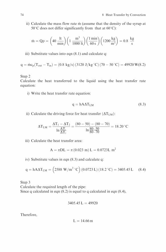
ii) Calculate the mass flow rate _m (assume that the density of the syrup at508C does not differ significantly from that at 608C):
_m ¼ Qr ¼ 40lt
min
� �1
m3
1000 lt
� �1min
60 s
� �1200
kg
m3
� �¼ 0:8
kg
s
iii) Substitute values into eqn (8.1) and calculate q:
Re ¼ ::::::::::::::::::::::::::::::::::::::::::::::::::::::::::::::::::::::::::::::::::::::::
Step 3Identify the regime of heat transfer:
l ::::::::::::::::::::::::::::::::::::::::::::::::::::::::::::::::::::::::::l ::::::::::::::::::::::::::::::::::::::::::::::::::::::::::::::::::::::::::l ::::::::::::::::::::::::::::::::::::::::::::::::::::::::::::::::::::::::::
Step 4Select the most suitable equation of Nu ¼ f Re;Prð Þ:
Nu ¼ :::::::::::::::::::::::::::::::::::::::::::::::::::::::::::::::::::::::::
76 8 Heat Transfer by Convection
Step 7Calculate h:
h ¼ ::::::::::::::::::::::::::::::::::::::::::::::::::::::::::::::::::::::::::::::::::::::::
Exercise 8.2
A horizontal steel pipe with 2 in nominal diameter has an outside surface tem-
perature of 80 8C. Calculate the heat transfer coefficient on the outside surface of
the pipe if the pipe is exposed to a room temperature of 20 8C.
Solution
Step 1Find the physical properties of the air.The physical properties must be calculated at the film temperature Tf (averageof air temperature and pipe surface temperature).
l ::::::::::::::::::::::::::::::::::::::::::::::::::::::::::::::::::::::::::::::::::::::::l ::::::::::::::::::::::::::::::::::::::::::::::::::::::::::::::::::::::::::::::::::::::::
Step 3Calculate the Grashof number:Since the pipe is horizontal, the characteristic dimension is the pipe diameter. Ina 2 in nominal diameter steel pipe, the outside diameter is 2.375 in or 0.0603 m.
l ::::::::::::::::::::::::::::::::::::::::::::::::::::::::::::::::::::::::::::::::::::::::l ::::::::::::::::::::::::::::::::::::::::::::::::::::::::::::::::::::::::::::::::::::::::
Step 3Calculate the Grashof number.Since the plate is vertical, the characteristic dimension is the plate height.
Gr ¼ :::::::::::::::::::::::::::::::::::::::::::::::::::::::::::::::
Step 5Select the most suitable equation of Nu ¼ f Gr;Prð Þ:
i) Calculate the product:
Gr � Pr ¼ :::::::::::::::::::::::::::::::::::::::::::::::::::::::::::::::::
ii) Select the equation suitable for the calculation of the heat transfer coeffi-cient in free convection on a vertical plane with ::::::::::::::::: < Gr�Pr < ::::::::::::::::::::::::
Nu ¼ 0:53Gr0:25Pr0:25
Step 6Calculate the Nusselt number:
Nu ¼ :::::::::::::::::::::::::::::::::::::::::::::::::::::::::::::::::::::::::
Step 7Calculate h:
h ¼ :::::::::::::::::::::::::::::::::::::::::::::::::::::::::::::::::::::::::::::
Air at a temperature of 60 8C flows inside a pilot plant cabinet dryer withdimensions 1m� 1m� 1m at a velocity of 3m=s. The walls of the dryer consistof two metal sheets of 2 mm thickness with 5 cm insulation in between.Calculate the heat losses through the side walls of the dryer if the heat transfercoefficient on the inside surface of the walls is 15W
�m2 8C, the thermal con-
ductivity of the metal wall and the insulation are 45W=m 8C and 0:045W=m 8Crespectively, and the outside air temperature is 20 8C.
Solution
Step 1Draw the process diagram:
60°C
20°C
hi = 15 W/m2°C ho
Two
Step 2Identify the regime of heat transfer:
l forced convection on the inside surface of the walll conduction through the walll natural convection on the outside surface of the walls
82 8 Heat Transfer by Convection
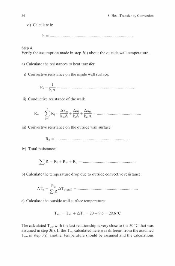
Step 3Calculate the heat transfer coefficient on the outside surface of the wall:
i) Find the physical properties of the air at the film temperature Tf:Since the wall temperature is not known, it must be assumed. Assume
the outside wall temperature (Two) is 30 8C. This assumption will be
ii) Calculate the Grashof number:Since the walls are vertical (side walls), the characteristic dimension is.....................................................................
Therefore:
Gr ¼ :::::::::::::::::::::::::::::::::::::::::::::::::::::::::::::::
Run the spreadsheet program Convection 1.xls. See how the value of h� varieswhen the outside wall surface temperature is adjusted in the cell F34. Adjust thespreadsheet program Convection 1.xls to calculate the heat losses from the side,the upper plane, and the lower plane of the dryer of Exercise 8.6. Compare theresults.Use the following empirical correlations for the physical properties of air as afunction of temperature (in 8C):
(Hints: Find suitable equations from the literature (e.g., Ref. 2, 3, 4) to calculatethe Nu number for a heated plate facing upward (top side of the dryer) and for aheated plate facing downward (bottom side of the dryer). Introduce the con-stants in the appropriate cells. Write the equations for the overall heat transfercoefficient and the heat transfer rate. Run the program.)
Exercise 8.8
Get familiar with the spreadsheet program Convection 2.xls. Run the program.See how the outside surface temperature of the vertical wall of the dryer ofExercise 8.6 and the heat transfer coefficient ho vary when the inside airtemperature of the dryer varies from 50 8C to 200 8C. Adjust the spreadsheet
Exercises 85
and plot how the heat losses through the vertical wall are affected when the
inside air temperature of the dryer varies from 50 8C to 200 8C.
Exercise 8.9
A loaf of bread with dimensions 0.25 m x 0.10 m x 0.10 m is exposed to room
temperature as it exits from the oven. Develop a spreadsheet program to
calculate the heat transfer coefficient on the top horizontal surface of the bread
as it cools down from 150 8C to 35 8C. Plot the heat transfer coefficient vs. thebread surface temperature. Assume a room temperature of 21 8C and uniform
bread surface temperature. (Hints: Find a suitable equation from the literature
(e.g., Ref. 2, 3, 4) to calculate the Nusselt number for a heated plate facing
upward. Use as the characteristic dimension the arithmetic mean of the dimen-
sions of the rectangle. Use the empirical correlations given in Exercise 8.7 for the
physical properties of the air. Calculate Nu and then h. Use the IF function in the
cell that gives the bread surface temperature and ITERATE to reduce the bread
surface temperature from 150 8C to 35 8C.)
Exercise 8.10
A liquid food is heated at a rate of 1 kg/s in a double-pipe heat exchanger. The
liquid enters the inside tube at 10 8C and exits at 70 8C. Water is used as the
heating medium, entering the annular space of the heat exchanger at 90 8C,flowing in a countercurrent mode, and exiting at 60 8C. If the overall heat
transfer coefficient of the heat exchanger is 200W/m2 8C, calculate the requiredwater flow rate, the required heat transfer area, and the effectiveness of the heat
exchanger. Use a value of 3.5 kJ/kg 8C for the heat capacity of the liquid and
4.18 kJ/kg 8C for the water.
Solution
Step 1Draw the process diagram:
10°C 70°C
60°C
90°C m
1 kg/s
.
Step 2State your assumptions:....................................................................................
86 8 Heat Transfer by Convection
Step 3Write an enthalpy balance on the heat exchanger and calculate the mass flowrate of water:
ii) Find the correction factor from an appropriate diagram from the litera-ture (e.g., Ref. 3, 4).With the above values of the dimensionless ratios, thecorrection factor for a 1-2 heat exchanger is 0.55. Therefore the correctedmean temperature difference is:
Calculate the mean temperature difference and the area of the heat exchanger ofExercise 8.11 if saturated steam at 101325 Pa absolute pressure is used as theheating medium instead of water. Use the same values for the temperature ofthe liquid food. Assume that the overall heat transfer coefficient in this case is300W
�m2�C.
Solution
Step 1Calculate the mean temperature difference:The temperature of the heating medium is: :::::::::::::::::::::::::::::::::::::::
The correction factor for the mean temperature difference for a multiple-passheat exchanger when one of the fluids undergoes a phase change is 1.Therefore:
A ¼ ::::::::::::::::::::::::::::::::::::::::::::::::::::::::::::::::::::::::::::::::::::::::::::::::
Exercise 8.13
Milk is pasteurized at a rate of 1:5kg=s in a plate heat exchanger that consists of aheat regeneration section, a heating section, and a cooling section. The milkenters the regeneration section at 5 8C and exits at 45 8C. It then enters theheating section where it is heated up to 72 8C, flows through the holder, and
Exercises 89
returns to the regeneration section where it is cooled to 32 8C. From the regen-erator, it flows to the cooling section where it is cooled down to 5 8C. Calculate 1)the required heat transfer area of each section, 2) the required flow rate of theheating water in the heating section, and 3) the brine exit temperature in thecooling section. It is given that the streams in each section flow in countercurrentmode; the heating water enters the heating section at 90 8C and exits at 80 8C; thebrine enters the cooling section at –5 8C at a flow rate of 1kg=s; the overall heattransfer coefficients are 1100W
�m2�C for the regenerator, 1300W
�m2�C for the
heating section, and 800W�m2�C for the cooling section; the heat capacities
throughout the process are 3:9kJ�kg �C for the milk, 4:19kJ
�kg �C for the
water, and 3:5kJ�kg �C for the brine.
Solution
Step 1Draw the process diagram:
milk in5°C
milk out
brine in–5°C hot water in
90°C
hot water outbrine out
Holding tube
Regenerationsection
Heatingsection
Coolingsection
5°C
72°C
72°C
80°C
45°C32°C
Step 2Calculate the heat transfer area in the regenerator.
i) Calculate the heat transferred from the hot stream to the cold stream:
qR ¼ _mmcp Thot in � Thot outð Þ ¼ ::::::::::::::::::::::::::::::::::::
ii) Calculate the driving force for heat transfer (mean temperature differ-ence �Tm).Since
L ¼ vmaxt ¼ :::::::::::::::::::::::::::::::::::::::::::::::::::::::::::
Step 2Develop a spreadsheet program to calculate the thickness of the insulation byiteration.
92 8 Heat Transfer by Convection
i) Calculate the heat that must be removed so that the temperature of themilk drops by 0.1 8C.
ii) Select a value for the insulation thickness.iii) Calculate the overall heat transfer coefficient.iv) Calculate heat losses with the heat transfer rate equation.v) If heat losses calculated in iv) are higher than those calculated in
i), increase the thickness of the insulation and repeat the calculationsfrom step ii). ITERATE to increase the thickness of insulation until theheat losses calculated in iv) are equal to the heat calculated in i). Use theIF function in the cell that gives the insulation thickness.
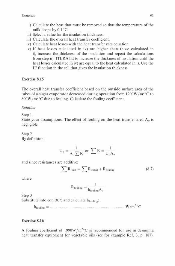
Exercise 8.15
The overall heat transfer coefficient based on the outside surface area of the
tubes of a sugar evaporator decreased during operation from 1200W�m2�C to
800W�m2�C due to fouling. Calculate the fouling coefficient.
Solution
Step 1State your assumptions: The effect of fouling on the heat transfer area Ao isnegligible.
Step 2By definition:
Uo ¼1
Ao
PR
orX
R ¼ 1
UoAo
and since resistances are additive:XRfinal ¼
XRinitial þRfouling (8:7)
where
Rfouling ¼1
hfoulingAo
Step 3Substitute into eqn (8.7) and calculate hfouling:
A fouling coefficient of 1990W�m2�C is recommended for use in designing
heat transfer equipment for vegetable oils (see for example Ref. 3, p. 187).
Exercises 93
How much more heat transfer area will be required in a heat exchanger tocompensate for the reduction in the overall heat transfer coefficient due tothis fouling? The overall heat transfer coefficient based on the inside area ofthe tubes for the clean heat exchanger is 300 W/m2 8C.
Solution
Step 1State your assumptions
l The effect of fouling on the diameter of the tubes is negligible.l The heat transfer driving force will be the same in the clean and the
fouled heat exchangers.l The heat transferred will be the same in the clean and the fouled heat