Chapter 8 Numerical Simulation of Core Melt Accidents 8.1. Integral and mechanistic computer codes The development of computer codes for the numerical simulation of core melt accidents began in the United States in the 1970s to back up probabilistic studies, such as those referred to in the American WASH 1400 report [1]. The TMI-2 accident in the United States in 1979 spurred efforts to improve simulation of this type of accident and develop level 2 probabilistic safety assessments (PSAs) in the country. Another major report following the WASH 1400 report included a probabilistic study of five US reactors [2]. It was in the late 1980s that the Europeans and Japanese decided to develop their own core melt accident simulation codes and probabilistic safety assessments. Over this period, these codes came into gradual use for elaborating and assessing methods for preventing core melt accidents – or mitigating their impact – as well as for training reac- tor operators. Two types of code were developed: – integral codes (or software systems) designed to simulate the entire core melt accident, from the initiating event up to and including any radioactive release outside the containment; – detailed or mechanistic codes, used to simulate in greater detail the phenomena involved in a particular accident phase, for example core damage, fission product release or hydrogen combustion inside the containment.
Transcript
Chapter 8Numerical Simulation
of Core Melt Accidents
8.1. Integral and mechanistic computer codesThe development of computer codes for the numerical simulation of core melt
accidents began in the United States in the 1970s to back up probabilistic studies, such as those referred to in the American WASH 1400 report [1]. The TMI-2 accident in the United States in 1979 spurred efforts to improve simulation of this type of accident and develop level 2 probabilistic safety assessments (PSAs) in the country. Another major report following the WASH 1400 report included a probabilistic study of five US reactors [2]. It was in the late 1980s that the Europeans and Japanese decided to develop their own core melt accident simulation codes and probabilistic safety assessments. Over this period, these codes came into gradual use for elaborating and assessing methods for preventing core melt accidents – or mitigating their impact – as well as for training reac-tor operators.
Two types of code were developed:
– integral codes (or software systems) designed to simulate the entire core melt accident, from the initiating event up to and including any radioactive release outside the containment;
– detailed or mechanistic codes, used to simulate in greater detail the phenomena involved in a particular accident phase, for example core damage, fission product release or hydrogen combustion inside the containment.
390 Nuclear Power Reactor Core Melt Accidents
8.1.1. Integral codes
Following the TMI-2 accident, the United States simultaneously started to develop two integral codes in the 1980s, one called MAAP for the nuclear industry and another, MELCOR, intended for the regulatory authorities. At the end of the 1980s, Japan and France began to develop analogue codes, namely THALES [2], developed by JAERI [3] and ESCADRE by IRSN [4]. IRSN then decided to work with GRS on the joint development of ASTEC, an integral code to replace ESCADRE. An ambitious project was started up at NUPEC in Japan using the SAMPSON system of detailed codes [5] but around 2001, related developments came to a virtual standstill owing to a decline in R&D work on core melt accidents in Japan. The Japanese Atomic Energy Agency (JAEA, successor to JAERI) has recently restarted development work on the THALES code. In the early 2000s, Russia began to develop a code system called SOCRAT [6].
There are five integral codes in the world, namely MAAP, MELCOR, ASTEC, SAMPSON and SOCRAT (this excludes certain special codes used to simulate core melt accidents in Canadian-designed CANDU heavy-water reactors, such as ISAAC, a code developed by KAERI in South Korea). Of these five codes, only three are in widespread use:
– ASTEC, jointly developed by IRSN and its German counterpart, GRS;
– MAAP4, developed by the American company Fauske & Associates, Inc. (FAI);
– MELCOR, developed by Sandia National Laboratories (SNL) in the United States for the US Nuclear Regulatory Commission (US NRC).
Integral codes must meet the following requirements:
– provide exhaustive coverage of all the physical phenomena involved in a core melt accident;
– simulate the behaviour of the main reactor safety systems;
– fully incorporate couplings between phenomena, such as the decrease in residual heat according to fission product release from the fuel, metal oxidation according to the quantity of oxygen or steam available, or corium cooling in the reactor pit during corium-concrete interaction as a result of radiation and convection in the containment;
– modular design to allow comparisons with experimental results in particular;
– high-speed performance to calculate a large number of level 2 PSA scenarios in a reasonable time. To achieve this, computing time must be less than real accident time.
Integral codes are used in reactor safety studies, particularly to estimate foreseeable radioactive releases, and in level 2 PSAs. They are also used in studies on the management of a possible core melt accident with a view to defining or improving severe accident operating guidelines. Another example of use is to verify the design of pressuriser steam bleed valves or recombiners in the containment building.
Numerical Simulation of Core Melt Accidents 391
The main physical fields covered are:
– RCS and secondary coolant system thermal-hydraulics from the start of the accident;
– core melting, with the release of fission products from the fuel rods and of aero-sols from the structural elements inside the reactor pressure vessel, such as con-trol rods, grids, etc.;
– relocation of corium to the lower head of the reactor vessel, that may result in vessel failure and flow of corium in the reactor pit;
– interaction between the molten core and the concrete of the reactor pit basemat (MCCI);
– transport and deposition of fission products and aerosols in the RCS and secondary coolant system;
– thermal-hydraulics and hydrogen combustion in the containment;
– transport and deposition of fission products and aerosols in the containment;
– fission product chemistry (particularly iodine and ruthenium) in the containment, and the possibility of fission product release to the environment.
Integral codes do not generally cover steam explosion or containment mechanical strength, which are covered by more specific codes.
Core melt accidents include transient phenomena in solid, liquid or gaseous media involving mass, momentum and energy exchanges. Integral codes must couple all these phenomena, which come into play on different spatial and temporal scales. Some phe-nomena, such as direct containment heating for example, last mere seconds, while others, such as the pressure increase due to gas release during MCCI, chemical reactions between cladding and fuel, or steam flows along the entire height of the core, can last several hours. Of course, these codes also involve various scientific disciplines, including thermal science, thermal-hydraulics, structural mechanics and chemistry.
For each component concerned, equations for conservation of mass and internal energy are solved in volumes, called control volumes, that define a spatial mesh. The RCS and secondary coolant system and the containment may be represented by any number of volumes, usually between 10 and 50 for the containment1. The reactor core is represented by a 2D axisymmetric mesh, generally composed of four to seven radial rings and 10 to 30 axial volumes.
The corium during MCCI is discretised in one, two or three volumes representing averaged layers (metal on the one hand, heavy and light oxides resulting from concrete decomposition on the other).
1. Except for MAAP4, where the maximum number is 14 for the RCS and two for the secondary coolant system.
392 Nuclear Power Reactor Core Melt Accidents
Computing time is significantly affected by the degree of refinement selected for discretisation into control volumes. Computing times of one or two hours per day of accident can be achieved using the minimum numbers of volumes mentioned above, but doing so may make results less reliable. Thermal-hydraulic models play a key role in integral codes as they are intricately linked to other models. Each control volume generally contains two temperature zones, a fluid zone (single-phase liquid or two-phase boiling) and a gaseous zone that may include a water mist. These volumes can be surrounded by solid, heat-conducting structures. They are connected by junctions. The velocities of fluids flowing through these junctions are calculated by solving the fluid momentum equations: the average velocity of the fluid is calculated in the transient state using the generalised Bernoulli equation, making allowance for head loss. The difference in velocity between liquid and gas is then calculated from this average velocity using an “inter-phase slip” correlation. For the RCS and secondary coolant system, the ASTEC code uses more complex modelling of 1D “pipe” volumes containing a two-phase mixture. The thermal-hydraulic models of the RCS and secon dary coolant system and the containment are closely coupled by the modelling of heat exchanges between the systems and containment or by the discharge of water or steam from the systems to the containment in the event of a pipe break. This allows simple modelling of some automatic reactor functions, such as the start-up of certain systems (safety injection, containment spray) at high containment pressure thresholds.
Integral codes are large, ranging from 400,000 to 500,000 instructions and 1000 to 1500 subroutines for ASTEC and MELCOR, and around 350,000 instructions and 700 subroutines for MAAP. They are made up of modules corresponding more or less to the main areas of the reactor. These modules are connected by a computer program that manages changes in the time steps of the numerical solution scheme, data exchange and conservation of mass and energy. The programming language is Fortran 95 or later.
An essential feature of these codes is that they allow the user to formulate hypotheses for the accident under study as flexibly and as simply as possible, often using a specific command language or a human-machine interface. This makes it possible to simulate the safety systems involved during the accident as well as the accident management procedures implemented by the operators:
– for the RCS and secondary coolant system: intentional depressurisation, pouring water onto the damaged core in the reactor vessel, etc.;
– for the containment: spraying, recombiners, ventilation, filters, etc.
Other requirements for these integral codes concern the numerical robustness and availability of user-friendly tools allowing users to prepare calculations and make use of their results, or stop calculations at any point during the accident, save the results, then continue calculations until the end of the accident, adjusting assumptions as necessary (for example, restarting the safety systems).
Thanks to improved computer performance and expanding knowledge, detailed models can now be incorporated in the integral codes mentioned above. Until the late
Numerical Simulation of Core Melt Accidents 393
1990s, models had to be as simple and fast as possible and highly flexible for the pur-poses of sensitivity studies. Despite the growing sophistication of models, however, integral codes continue to complement mechanistic codes, which are used to simulate a particular phenomenon. This is the case of Computational Fluid Dynamics (or CFD) codes, which are used to assess the hydrogen risk in the containment or to model steam explosions (Sections 5.2.2 and 5.2.3).
8.1.2. Mechanistic codes
The principal mechanistic codes used around the world are, with the developing organisations in parentheses:
– for core damage: ATHLET-CD (GRS in Germany), ICARE/CATHARE (IRSN), RELAP/SCDAPSIM (ISS in the USA), SCDAP/RELAP5 (INL in the USA);
– for the containment: COCOSYS (GRS), TONUS (IRSN), FUMO (University of Pisa in Italy), GOTHIC (AECL in Canada), CONTAIN (developed by ANL in the USA but now replaced by the integral code MELCOR);
– for steam explosion: IKEDEMO (University of Stuttgart in Germany), MC3D (IRSN);
– for large structural mechanics: finite-element codes such as ABAQUS (United States) and CAST3M (CEA);
– for thermal-hydraulics: CFD codes designed to solve Navier-Stokes equations in 3D geometry such as CFX (off-the-shelf software), GASFLOW (KIT, ex-FzK in Germany), TONUS (IRSN).
These codes are generally used to simulate part of an accident scenario or a par-ticular area of a nuclear power plant, such as the RCS and secondary coolant system or the containment. Their main goal is to reduce uncertainties and provide a more detailed understanding of physical phenomena. For this reason, they include detailed, “realistic” state-of-the-art models known as best-estimate models. Mechanistic codes and integral codes adopt different approaches. The first usually calculate numerical solutions for differential equations, while integral codes sometimes use correla-tions, which implies that they can only be used within the scope of the correlations in question.
Mechanistic codes often serve as references to determine the validity of integral code results.
Computing time is generally long; with very high spatial and temporal discretisation, it can take several weeks to perform calculations for one day of accident.
394 Nuclear Power Reactor Core Melt Accidents
8.2. General approach to code development and validation
8.2.1. Code development
Code development is generally carried out in the following steps, possibly with itera-tions between them:
– step 1: defining code objectives, including scope and required performance in terms of computing time, etc.;
– step 2: preparing general specifications such as structure, programming lan-guages, degree of detail in models, numerical solution schemes, etc.;
– step 3: preparing detailed specifications for certain models as required and, where necessary, building prototype;
– step 4: developing physical models, generally based on experimental data;
– step 5: developing the code by implementing the physical models and adjusting them to the appropriate numerical scheme;
– step 6: checking the code by comparing the results it produces for simple problems with analytical solutions, and verifying conservation of mass and energy, con-sistency of results obtained with various computers systems, correct coupling between phenomena, etc.
8.2.2. Code validation
The purpose of the validation process is to ensure that the code gives a true represen-tation of physical phenomena and that it can reliably simulate a core melt accident in a reactor, from beginning to end.
“Validation Strategy of Severe Accident codes” [7] or VASA, a project carried out between 1999 and 2003 as part of the fourth European R&D framework programme (FP4) and coordinated by GRS with active support from IRSN, studied various approaches to code validation. One of its main conclusions was to recommend a dual approach that not only takes into consideration physical phenomena as such, but also their impact on reactor safety.
The two approaches complement each other as the second determines the degree of accuracy required for simulating phenomena. It should be noted that for the second approach, all the reactor safety systems must be modelled in the code.
Validation is generally carried out in three steps:
– validating a physical model implemented in the code, based on the results of separate-effect tests, often carried out on a small scale, then validating the code based on the results of coupled-effect tests covering a set of several physical
Numerical Simulation of Core Melt Accidents 395
phenomena. The latter tests are often carried out using simulant materials and can also represent the behaviour of a real reactor component;
– validating the code using integral tests. These are often carried out on a relatively large scale (for example on rod clusters of actual height) and using real materials, which makes it possible to check that the various models are suitably coupled and that no important phenomena have been neglected;
– extrapolating the code to accident situations liable to affect power reactors, in particular through scale-effect studies, sensitivity studies on various model para-meters (physical and numerical) and comparisons with other codes, and applying it to emergency transients actually encountered in reactors, such as the TMI-2 and Fukushima Daiichi accidents in the United States and Japan respectively.
When these steps are considered sufficiently complete (they need to be repeated regularly as knowledge advances), default values and variation ranges for various model parameters can be recommended to users. The conclusions of this validation process can then point to ways of improving the code models.
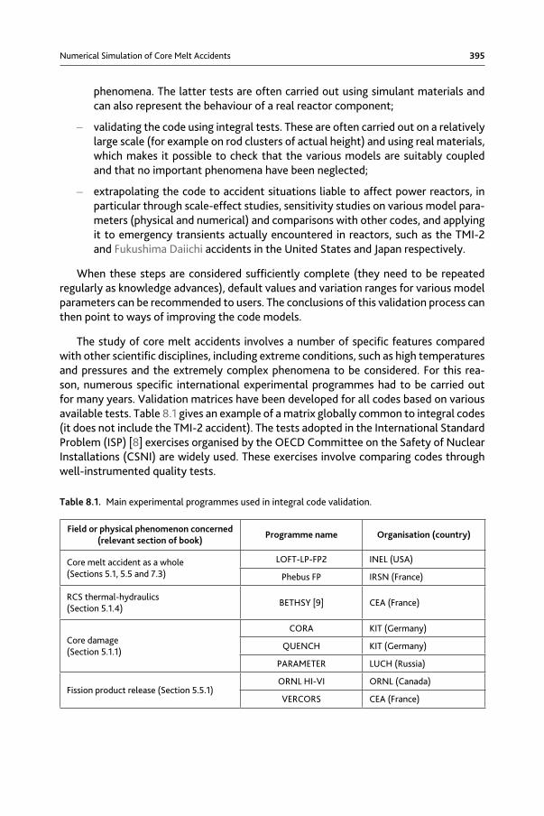
The study of core melt accidents involves a number of specific features compared with other scientific disciplines, including extreme conditions, such as high temperatures and pressures and the extremely complex phenomena to be considered. For this rea-son, numerous specific international experimental programmes had to be carried out for many years. Validation matrices have been developed for all codes based on various available tests. Table 8.1 gives an example of a matrix globally common to integral codes (it does not include the TMI-2 accident). The tests adopted in the International Standard Problem (ISP) [8] exercises organised by the OECD Committee on the Safety of Nuclear Installations (CSNI) are widely used. These exercises involve comparing codes through well-instrumented quality tests.
Table 8.1. Main experimental programmes used in integral code validation.
Field or physical phenomenon concerned (relevant section of book)
Programme name Organisation (country)
Core melt accident as a whole (Sections 5.1, 5.5 and 7.3)
Field or physical phenomenon concerned (relevant section of book)
Programme name Organisation (country)
Fission product transport in the RCS and containment (Section 5.5.2)
FALCON [10] AEAT (UK)
VERCORS HT CEA (France)
LACE [11] INEL (USA)
KAEVER [12] Battelle (Germany)
Vessel failure (Section 5.1.3)
LHF-OLHF SNL (USA)
FOREVER KTH (Sweden)
Heat transfers in a corium pool (Sections 5.4.1 and 5.4.2)
COPO VTT (Finland)
ULPU [13] UCLA (USA)
BALI CEA (France)
Fragmentation of corium in water (Section 5.2.3)
FARO and KROTOS JRC Ispra
Direct containment heating (Section 5.2.1)
SURTSEY IET SNL (USA)
DISCO (C, H) KIT (Germany)
MCCI (Section 5.3)
BETA KIT (Germany)
CCI ANL (USA)
ACE and MACE ANL (USA)
Iodine chemistry in the containment (Section 5.5.5)
ACE/RTF and Phebus/RTF AECL (Canada)
CAIMAN CEA (France)
EPICUR IRSN (France)
Thermal-hydraulics in the containment (Section 5.2.2)
NUPEC [14] NUPEC (Japan)
VANAM [14] Battelle (Germany)
TOSQAN [15] IRSN (France)
MISTRA [15] CEA (France)
Hydrogen combustion in the containment (Section 5.2.2)
HDR Battelle (Germany)
RUT RRC-KI (Russia)
8.3. ASTECThe Accident Source Term Evaluation Code, or ASTEC, has been jointly developed
since 1995 by IRSN and its German counterpart, GRS [16]. It played a key role in the research carried out by the Severe Accident Research Network of Excellence, or SARNET, under the European Commission framework programmes, FP6 and FP7 from 2004 to 2013. Within this context, it gradually incorporated models of all knowledge generated by the network, and is used by the partners to conduct a considerable amount of work on validation and comparison with other codes on reactor applications [17]. ASTEC has now become the European reference code.
Numerical Simulation of Core Melt Accidents 397
8.3.1. Capabilities
An initial series of versions, V0, was developed until 2003, followed by the V1 series until 2009. The first version of the V2 series was commissioned mid-2009. The major change compared with the V1 series concerns core damage: the models in the V2 series, developed using IRSN’s mechanistic code ICARE2 [20], are capable of simulating in 2D the flow of corium inside the core, and its progression towards the lower head through the barrel and lower core plates, as observed during the TMI-2 accident (whereas ASTEC V1 modelled flows in one dimension along the rods). Another major improvement con-cerns iodine and ruthenium modelling in the RCS and secondary coolant system and in the containment.
The V2 versions can be applied to various types of Generation II reactor, French PWRs (900, 1300 and 1450 MWe series), German 1300 MWe Konvoi reactors, Westinghouse 1000 MWe PWRs and Russian-designed 440 and 1000 MWe VVERs. They can also be used for new Generation III reactor designs such as the EPR with its core catcher, or reactors, such as the AP1000, designed to retain the corium inside the reactor vessel and cooling the vessel by flooding the reactor pit (as seen in Generation II VVER 440 reactors on which this cooling system was installed [18]). Research at GRS has shown that the ASTEC V2 code could also be used on boiling water reactors (BWRs), except during the core damage phase, for which models are currently being adapted. The same is true for CANDU and high-temperature reactors (HTRs), as demonstrated by the work of BARC in India and PBMR in South Africa respectively.
Another application of ASTEC is in simulating accidents in fuel storage pools, such as the one that occurred at the Paks NPP in Hungary [19].
IRSN makes intensive use of ASTEC in its Level 2 PSAs and in studies on foreseeable radioactive release in the event of a core melt accident at French 900 MWe and 1300 MWe PWRs. Similar work is in progress for the EPR.
Figure 8.1 shows the different ASTEC modules and how they are coupled. The fact that ASTEC is highly modular simplifies validation, which can be carried out on tests using only one module or suite of modules.
Version V2.0 of ASTEC was distributed to nearly 40 organisations in twenty coun-tries, mostly in the European Union, but also in Russia, China, India, South Korea and South Africa.
All the phases of an accident can be simulated during reactor power operation or with the reactor shut down, except for the detailed effects of air entering the reactor vessel, which will be covered in the next major upgrade, V2.1. All accident scenarios can be simulated – loss-of-coolant accident, steam generator tube rupture, total loss of emergency power supply, and total loss of steam generator feedwater supply – as well as most emergency operation procedures, such as depressurisation of the RCS and secondary coolant system, water injection onto a slightly damaged core, containment spraying, containment venting and filtering radioactive release. Certain devices inside
398 Nuclear Power Reactor Core Melt Accidents
the containment, such as catalytic hydrogen recombiners, can also be represented, as can suppression pools with gas bubbling in VVER 440 reactors or HTRs.
A numerical approach with five differential equations and an algebraic inter-phase slip algorithm is used to model RCS and secondary coolant system two-phase thermal-hydraulics. A zero-dimensional “zone-based” approach is used to describe corium behaviour in the reactor pit during MCCI. This may involve changes among layers as a result of stratification and layer inversion (see Section 5.3 for further details on MCCI). This approach is also used for modelling thermal-hydraulics in the containment.
All the basic data required for calculations are gathered in a single base called the Material Data Bank, which includes not only the physical properties of materials and mixtures (conductivity, viscosity, etc.) but also chemical reactions and fission product isotopes (radioactive decay). The corium thermophysical properties come from the European reference base, NUCLEA [21].
The computing time for a severe accident scenario is generally close to real time on a PC in a Windows or Linux environment. Less refined spatial meshing can reduce computing time to a few hours per day of accident.
Users have access to SUNSET, a tool designed for automatically launching a series of sensitivity studies for uncertainty analysis.
Figure 8.1. ASTEC V2 structure
Numerical Simulation of Core Melt Accidents 399
8.3.2. Validation status mid-2015
During the 1990s, an intensive effort was undertaken to validate codes such as ESCADRE, RALOC and FIPLOC, from which ASTEC was developed. This work laid solid foundations for validation. The basic validation matrix is composed of some thirty experiments, mainly those shown in Table 8.1. As these concern crucial phenomena involved in core melt accidents, the matrix is applied to each major upgrade to specify model uncertainties. For each module, validation is complemented by campaigns which, although less frequent, cover all available experiments (some forty experi-ments on fission product release for example). It is also performed by IRSN’s partners in SARNET on reference experiments used for international computer code intercom-parison exercises (ISP). Examples include BETHSY 9.1b (ISP27) for RCS and secondary coolant system thermal-hydraulics, KAEVER (ISP44) for aerosol behaviour in the con-tainment, and Phebus FPT1 (ISP46) for the accident as a whole.
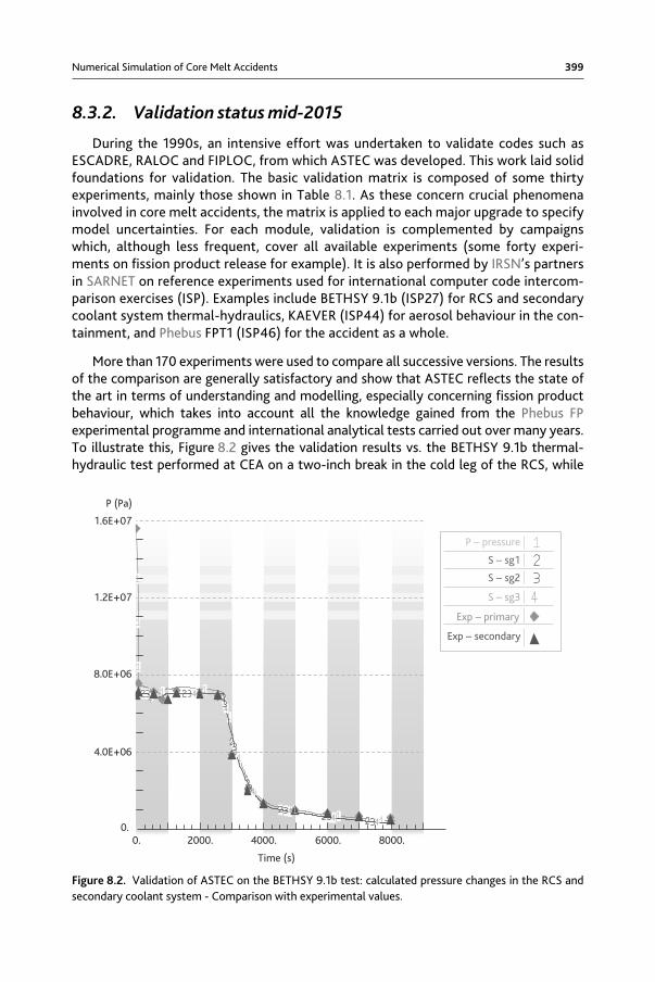
More than 170 experiments were used to compare all successive versions. The results of the comparison are generally satisfactory and show that ASTEC reflects the state of the art in terms of understanding and modelling, especially concerning fission product behaviour, which takes into account all the knowledge gained from the Phebus FP experimental programme and international analytical tests carried out over many years. To illustrate this, Figure 8.2 gives the validation results vs. the BETHSY 9.1b thermal-hydraulic test performed at CEA on a two-inch break in the cold leg of the RCS, while
P – pressure
S – sg1
S – sg2
S – sg3
Exp – primary
Exp – secondary
P (Pa)
1.6E+07
1.2E+07
8.0E+06
4.0E+06
0.0. 2000. 4000. 6000. 8000.
Time (s)
Figure 8.2. Validation of ASTEC on the BETHSY 9.1b test: calculated pressure changes in the RCS and secondary coolant system - Comparison with experimental values.
400 Nuclear Power Reactor Core Melt Accidents
Figure 8.3 shows the results obtained for the CAIMAN 97/02 test, also performed at CEA, to simulate the production of gas-phase molecular and organic iodine in the con-tainment during a severe accident.
Improvements to ASTEC models currently focus on reflooding of damaged cores, which is a crucial aspect of core melt accident management. As for all other codes, there is considerable room for improvement in ASTEC on this issue. This was highlighted by the interpretation of QUENCH and CORA experiments, especially the failure to repro-duce the hydrogen production peaks observed during these reflooding tests.
In addition to comparison with experimental results, it is also necessary to demon-strate that the code is capable of calculating all severe accidents liable to affect power reactors. ASTEC is therefore used in the IRSN level 2 PSA PWR 1300 studies concerning the main scenarios (RCS or secondary coolant system break, loss of emergency power supply, etc.), with variants for examining the impact of whether or not reactor safety systems are used. Nearly a hundred sequence calculations were performed to ensure that results are mutually consistent and that the trends obtained are physically credible.
0. 10. 20. 30. 40.
HOURS10-14
10-13
10-12
10-11
10-10MOL/L
Figure 8.3. Validation of ASTEC on the CAIMAN 97/02 test: changes in gas-phase iodine concentra-tions in the form of molecular iodine (I2) and organic iodine (CH3I).
Numerical Simulation of Core Melt Accidents 401
Comparisons were also made with other codes on certain accident scenarios. This is the case of comparisons made within SARNET with the MELCOR and MAAP4 integral codes and with mechanistic codes such as ICARE/CATHARE and CONTAIN, for various types of reactor, including PWR 900, PWR 1300, Konvoi 1300, VVER 440 and VVER 1000. Results were generally considered close, although deviations were observed during some phases in the scenarios. The models responsible for these deviations were identi-fied during these comparisons, which helped to quantify uncertainties in the assessment of certain physical phenomena.
8.3.3. ASTEC upgrade prospects
Several new models are being implemented in V2.1, the next major upgrade of ASTEC, which is scheduled for release in 2015. These are the results of interpretations of experimental programmes aimed at reducing uncertainties and include:
– for iodine and ruthenium transport chemistry in the RCS: IRSN’s CHIP tests (Sec-tion 5.5.6.2) carried out under the International Source Term Programme (ISTP) to qualify a new chemical kinetics model;
– for iodine and ruthenium chemistry in the containment: IRSN’s EPICUR tests (Section 5.5.6.2), also carried out as part of ISTP;
– for the spatial distribution of heat flux in the corium pool during MCCI: CEA’s VULCANO and CLARA tests and CCI project tests on real materials;
– for the effects of high fuel burnup and MOX fuel on core damage and fission product release: CEA’s VERCORS and VERDON tests;
– for damaged core reflooding: IRSN’s PRELUDE PEARL tests on debris bed cooling (and the related work done by SARNET partners).
At the same time work was carried out on adapting core damage models to BWRs, in collaboration with GRS and the University of Stuttgart, and to PHWR (Pressurized Heavy Water Reactors [incl. CANDU]), in collaboration with the BARC.
In the future activities of SARNET, ASTEC should continue to be used to build up knowledge on severe accidents. Initiatives are underway to reduce computing speeds, in particular through parallel computing.
Since 2009, work has been carried out on adapting ASTEC to accidents in Gen IV sodium-cooled, fast-neutron reactors and at nuclear fusion facilities such as ITER.
8.4. MAAPDevelopment work on the Modular Accident Analysis Program (MAAP) began in the
United States in the early 1980s for the purpose of PSA-related physical studies under the Industry Degraded Core Rulemaking (IDCOR) programme, which brought together some sixty American companies. When IDCOR came to an end, MAAP was acquired by
402 Nuclear Power Reactor Core Melt Accidents
the Electric Power Research Institute (EPRI), an American organisation, but development work is still carried out by Fauske & Associates, Inc (FAI).
Many nuclear operators have purchased a licence to use MAAP for the purpose of safety studies. They have formed a users’ group (MAAP Users’ Group or MUG) com-prising more than 55 organisations.
EDF uses MAAP for studying PWR core melt accidents including level 2 PSAs, hydro-gen recombiner design, reassessment of foreseeable release in the event of a core melt accident, studies to help prepare severe accident operating guidelines (GIAG), direct containment heating (DCH) studies and studying the slow rise in containment pressure.
Since it acquired the code in 1991, EDF has built up specific skills in developing and validating MAAP, in particular by comparing it with results obtained from other codes designed for power reactor applications.
Pursuing the same development approach, it began producing its own versions of MAAP as of 1996, integrating special features. EDF currently uses version 4.07a of the code, which is designed to model EPR accident sequences in addition to those con-cerning 900 et 1300 MWe PWRs.
8.4.1. Capabilities
The MAAP code is used to simulate accident situations in PWRs, including VVER and EPR designs, BWRs or PHWR reactors, with specific versions for each type of reactor. It focuses in particular on core melt sequences whatever the conditions (whether the reac-tor is operating or shut down).
Functional modelling is included for examining the impact of operator action on the progression of accident sequences.
Computing time is short - about two hours on a PC in a Linux environment to simu-late 24 hours real time for an accident sequence with core damage.
Fission product transport (release in the event of core damage, migration in the RCS and containment, chemistry) can be modelled to determine environmental release and surface and volume contamination in rooms.
For each control volume, MAAP solves conservation of mass and energy equations. Conservation of momentum equations are not differential equations and amount to Bernoulli equations.
The RCS, excluding the pressuriser, is represented by 14 volumes at the most, and the containment by no more than 30. The core is modelled axisymmetrically with a maximum of 175 mesh cells.
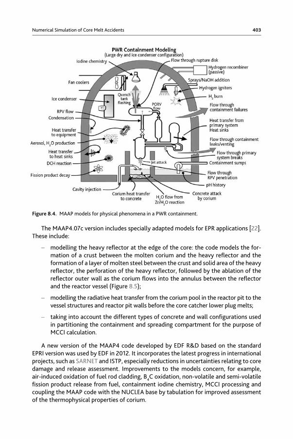
Figure 8.4 illustrates the main physical phenomena modelled by MAAP for the RCS and containment.
Numerical Simulation of Core Melt Accidents 403
The MAAP4.07c version includes specially adapted models for EPR applications [22]. These include:
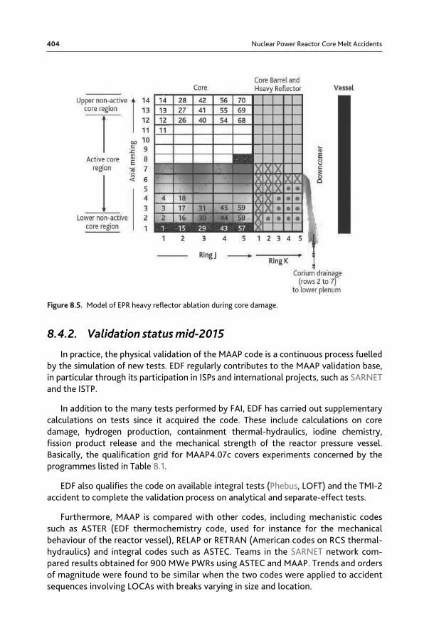
– modelling the heavy reflector at the edge of the core: the code models the for-mation of a crust between the molten corium and the heavy reflector and the formation of a layer of molten steel between the crust and solid area of the heavy reflector, the perforation of the heavy reflector, followed by the ablation of the reflector outer wall as the corium flows into the annulus between the reflector and the reactor vessel (Figure 8.5);
– modelling the radiative heat transfer from the corium pool in the reactor pit to the vessel structures and reactor pit walls before the core catcher lower plug melts;
– taking into account the different types of concrete and wall configurations used in partitioning the containment and spreading compartment for the purpose of MCCI calculation.
A new version of the MAAP4 code developed by EDF R&D based on the standard EPRI version was used by EDF in 2012. It incorporates the latest progress in international projects, such as SARNET and ISTP, especially reductions in uncertainties relating to core damage and release assessment. Improvements to the models concern, for example, air-induced oxidation of fuel rod cladding, B4C oxidation, non-volatile and semi-volatile fission product release from fuel, containment iodine chemistry, MCCI processing and coupling the MAAP code with the NUCLEA base by tabulation for improved assessment of the thermophysical properties of corium.
Figure 8.4. MAAP models for physical phenomena in a PWR containment.
404 Nuclear Power Reactor Core Melt Accidents
8.4.2. Validation status mid-2015
In practice, the physical validation of the MAAP code is a continuous process fuelled by the simulation of new tests. EDF regularly contributes to the MAAP validation base, in particular through its participation in ISPs and international projects, such as SARNET and the ISTP.
In addition to the many tests performed by FAI, EDF has carried out supplementary calculations on tests since it acquired the code. These include calculations on core damage, hydrogen production, containment thermal-hydraulics, iodine chemistry, fission product release and the mechanical strength of the reactor pressure vessel. Basically, the qualification grid for MAAP4.07c covers experiments concerned by the programmes listed in Table 8.1.
EDF also qualifies the code on available integral tests (Phebus, LOFT) and the TMI-2 accident to complete the validation process on analytical and separate-effect tests.
Furthermore, MAAP is compared with other codes, including mechanistic codes such as ASTER (EDF thermochemistry code, used for instance for the mechanical behaviour of the reactor vessel), RELAP or RETRAN (American codes on RCS thermal-hydraulics) and integral codes such as ASTEC. Teams in the SARNET network com-pared results obtained for 900 MWe PWRs using ASTEC and MAAP. Trends and orders of magnitude were found to be similar when the two codes were applied to accident sequences involving LOCAs with breaks varying in size and location.
Figure 8.5. Model of EPR heavy reflector ablation during core damage.
Numerical Simulation of Core Melt Accidents 405
8.4.3. MAAP upgrade prospects
At the beginning of 2015 EDF switched to MAAP 5.0, a major upgrade to the code. Version 5.0 incorporates most of the physical models developed by EDF for its own versions of MAAP 4, including damage to Ag-In-Cd or B4C control rods, zirconium oxidation at high temperatures and fission product release from the fuel matrix. It also includes many of the improvements made to physical models by FAI, some of which are listed below:
– RCS thermal-hydraulics: more detailed processing with the RCS broken down into 49 mesh units, single-phase or water-steam two-phase fluid processing, possibility of simulating safety injection in the cold leg only, improved modelling of natural circulation in the reactor vessel (especially between the annulus, core and upper plenum), improved modelling of the formation of water plugs and their impact on natural circulation, taking account of any reversal of flow in steam generator tubes;
– accumulator modelling: accumulators modelled as part of the RCS, accumu-lator wall modelled as a heat sink, nitrogen injection into the RCS from the accumulators;
– core modelling: addition of 1D neutronic and point kinetic models;
– modelling of corium retention in the reactor vessel: refinement of the reactor vessel axial mesh to 100 meshes, modelling of the variation in the critical dryout heat flux along the outer surface of the reactor vessel (according to the angle of inclination) when the vessel is assumed to be flooded, calculation of heat transfer by nucleate boiling between the outer surface of the reactor vessel and the liquid water in the reactor pit, modelling of insulation and of a gap between the reactor vessel and the insulation;
– new models of phenomena involved in containment heat transfers: natural and forced convection in containment compartments induced by a loss-of-coolant accident, wall condensation allowing for paint, gas entrainment of condensed water droplets on the wall, steam jet condensation in the flooded compartment, hydrogen combustion.
These improvements have been financed by some fifteen MAAP4 licence holders. After improving physical modelling, FAI focused on the numerical stability of MAAP5 in 2011-2012. Since the beginning of 2015, MAAP5 provides an alternative to MAAP4 for EDF research on core melt accidents.
8.5. MELCORMELCOR is an integral code developed by SNL since 1982 for the US NRC. It is used
as a tool for the comprehensive study of core melt accidents that might occur in light-water reactors (PWR designs including VVERs and BWRs) [23]. Applications also exist for RBMK reactors, as well as for PHWR reactors, albeit only on an exploratory basis. Foreign partners in the US NRC Cooperative Severe Accident Research Program (CSARP) contribute to the code validation process.
406 Nuclear Power Reactor Core Melt Accidents
The US NRC uses the code in reassessing radioactive releases from MOX or high-burnup fuels for example, appraising new reactor designs (such as the Westinghouse AP1000, ESBWR and US.EPR), realistically estimating the impact of core melt accidents for various types of reactor in operation in the United States, based on state-of-the-art knowledge, methods and software and taking into account the related uncertainties, and for studying accidents in spent fuel pools. On an international level, applications are particularly concerned with optimising accident management guidelines.
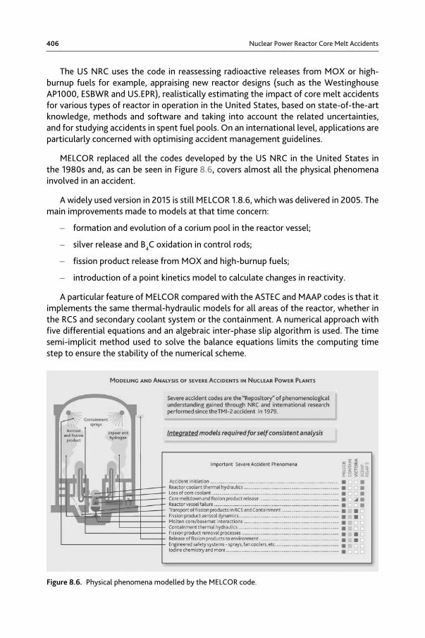
MELCOR replaced all the codes developed by the US NRC in the United States in the 1980s and, as can be seen in Figure 8.6, covers almost all the physical phenomena involved in an accident.
A widely used version in 2015 is still MELCOR 1.8.6, which was delivered in 2005. The main improvements made to models at that time concern:
– formation and evolution of a corium pool in the reactor vessel;
– silver release and B4C oxidation in control rods;
– fission product release from MOX and high-burnup fuels;
– introduction of a point kinetics model to calculate changes in reactivity.
A particular feature of MELCOR compared with the ASTEC and MAAP codes is that it implements the same thermal-hydraulic models for all areas of the reactor, whether in the RCS and secondary coolant system or the containment. A numerical approach with five differential equations and an algebraic inter-phase slip algorithm is used. The time semi-implicit method used to solve the balance equations limits the computing time step to ensure the stability of the numerical scheme.
Figure 8.6. Physical phenomena modelled by the MELCOR code.
Numerical Simulation of Core Melt Accidents 407
Users have access to a tool designed for automatically launching a series of sensitivity studies for uncertainty analysis.
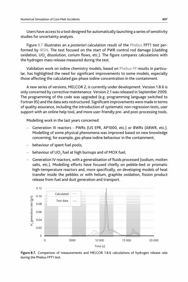
Figure 8.7 illustrates an a posteriori calculation result of the Phebus FPT1 test per-formed by IRSN. The test focused on the start of PWR control rod damage (cladding oxidation, UO2 dissolution, corium flows, etc.). The figure compares calculations with the hydrogen mass release measured during the test.
Validation work on iodine chemistry models, based on Phebus FP results in particu-lar, has highlighted the need for significant improvements to some models, especially those affecting the calculated gas-phase iodine concentration in the containment.
A new series of versions, MELCOR 2, is currently under development. Version 1.8.6 is only concerned by corrective maintenance. Version 2.1 was released in September 2009. The programming of the code was upgraded (e.g. programming language switched to Fortran 95) and the data sets restructured. Significant improvements were made in terms of quality assurance, including the introduction of systematic non-regression tests, user support with an online help tool, and more user-friendly pre- and post-processing tools.
Modelling work in the last years concerned:
– Generation III reactors - PWRs (US EPR, AP1000, etc.) or BWRs (ABWR, etc.). Modelling of some physical phenomena was improved based on new knowledge concerning, for example, gas-phase iodine behaviour in the containment;
– behaviour of spent fuel pools;
– behaviour of UO2 fuel at high burnups and of MOX fuel;
– Generation IV reactors, with a generalisation of fluids processed (sodium, molten salts, etc.). Modelling efforts have focused chiefly on pebble-bed or prismatic high-temperature reactors and, more specifically, on developing models of heat transfer inside the pebbles or with helium, graphite oxidation, fission product release from fuel and dust generation and transport.
Calculated
Test data
H2
gene
rati
on r
ate
(g/s
)
Time (s)
0
0.02
0.04
0.06
0.08
0.10
0.12
0 5000 10 000 15 000 20 000
Figure 8.7. Comparison of measurements and MELCOR 1.8.6 calculations of hydrogen release rate during the Phebus FPT1 test.
408 Nuclear Power Reactor Core Melt Accidents
References
[1] N. Rasmussen, Rapport WASH 1400, The reactor safety study, 1975.
[2] NUREG, 1150, Severe Accident Risks: An assessment for five US Nuclear Power Plants, 1991.
[3] M. Kajimoto et al., Development of THALES2, a Computer Code for Coupled Ther-mal-Hydraulics and Fission Product Transport Analysis for Severe Accidents at LWRs and its Application to Analysis of Fission Product Revaporization Phenomena, Proceedings of the ANS International Topical meeting on safety of thermal Nuclear reactors, Portland (USA), July 1991.
[4] B. Linet, A. Maillat, ESCADRE code development and validation - An overview, Pro-ceedings of the International Topical meeting Severe Accident Risk and management (SARM’97), Piestany (Slovakia), June 1997.
[5] M. Naitoh, S. Hosoda, C.M. Allison, Assessment of water injection as severe acci-dent management using SAMPSON code, Conference ICONE-13, Beijing, China, 16-20 May 2005.
[6] L.A. Bolshov, V.F. Strizhov, SOCRAT - The System of Codes for Realistic Analysis of Severe Accidents, Conférence ICAPP ‘06, Reno (United States), June 2006.
[7] H.-J. Allelein et al., Validation strategies for severe accident codes (VASA), EU Cosponsored research on Containment Integrity, EUR 19952 EN, Brussels, p. 295-324, 2000.
[8] CSNI: International Standard Problems (ISP), brief descriptions (1975-1999), NEA/ CSNI/R(2000)5, 2000.
[9] CSNI integral test facility validation matrix for the assessment of thermal-hydrau-lic codes for LWR LOCA and transients, NEA/CSNI/R(96)-17, 1996.
[10] A.M. Beard, P.J. Bennett, B.R. Bowsher, J. Brunning, The Falcon Programme: Cha-racterisation of Multicomponent Aerosols in Severe Nuclear Reactors Accidents, Journal of Aerosol Science 23, S831, 1992.
[11] F. Rahn, R. Sher, R.C. Vogel, Summary of the LWR aerosol containment experiments (LACE) programme, IAEA Symposium Severe Accidents in Nuclear Power Plants, Sorrento, 21-25 March 1988, ISBN 92-0-020188-1.
[12] M. Firnhaber, K. Fischer, S. Schwarz, G. Weber, ISP-44 KAEVER tests – Experi-ments on the behaviour of core-melt aerosols in a LWR containment, NEA/CSNI/R(2003)5, 2003.
[13] Theofanous and Syri, The coolability limits of a reactor pressure vessel lower head, Nuclear Engineering and Design 169 (1-3), 59-76, 1997.
[14] SOAR on Containment Thermal hydraulics and Hydrogen distribution, NEA/CSNI/R(99)-16, 1999.
Numerical Simulation of Core Melt Accidents 409
[15] H.J. Allelein et al., International standard problem ISP-47 on containment ther-mal-hydraulics, Final report, NEA/CSNI/R(2007)10, 2007.
[16] P. Chatelard, N. Reinke, S. Arndt, S. Belon, L. Cantrel, L. Carenini, K. Chevalier-Jabet, F. Cousin, J. Eckel, F. Jacq, C. Marchetto, C. Mun, L. Piar. ASTEC V2 severe accident integral code main features, current V2.0 modelling status, perspectives. Nuclear Engineering and Design 272 (2014),119-135.
[17] T. Albiol, J.P. Van Dorsselaere, N. Reinke, SARNET: a success story. Survey of major achievements on severe accidents and of knowledge capitalization within the ASTEC code, Conférence EUROSAFE, Paris, November 2008.
[18] D. Tarabelli, G. Ratel, P. Pélisson, G. Guillard, M. Barnak, P. Matejovic, ASTEC appli-cation to in-vessel corium retention, Nuclear Engineering and Design 239, 1345-1353, 2009.
[19] J. Elter, P. Matejovic, Proposal of in-vessel corium retention concept for PAKS NPP, OECD MASCA2 Seminar, Cadarache (France), 11-12 October, 2007.
[20] P. Chatelard, J. Fleurot, O. Marchand, P. Drai, Assessment of ICARE/CATHARE V1 severe accident code, Conférence ICONE-14, Miami, Florida (USA), 17-20 July 2006.
[21] B. Cheynet, P. Chaud, P.Y. Chevalier, E. Fischer, P. Mason, M. Mignanelli, NUCLEA: Thermodynamic Properties and Phase Equilibria in the Nuclear Systems of Inte-rest, Journal de Physique IV 113, 61-64, 2004.
[22] E. Williams, R. Martin, P. Gandrille, R. Meireles, R. Prior, C. Henry, Q. Zhou, Recent revisions to MAAP4 for US EPR Severe Accident Applications, Conference ICAPP 08, Anaheim (California, USA), June 2008.
[23] R.O. Gauntt et al., MELCOR Computer Code Manuals, Version 1.8.6, Rapport SAND 2005-5713, 2005.