134
NCCU Wireless Comm. Lab. Chapter 8 OFDM Applications

NCCU Wireless Comm. Lab.
Chapter 8OFDM Applications

NCCU Wireless Comm. Lab.2
Contents8 OFDM Applications
8.1 DAB 8.2 HDTV8.3 Wireless LAN Networks
8.3.1 HIPERLAN/2 8.3.2 IEEE 802.11a8.3.3 IEEE 802.11g
8.4 IEEE 802.16 Broadband Wireless Access System

NCCU Wireless Comm. Lab.3
8.1 Digital Audio Broadcasting (DAB)

NCCU Wireless Comm. Lab.4
8.1.1 Introduction to DABCurrent analog FM radio broadcasting system cannot satisfy the demands of the future, which are
excellent sound quality large number of stations small portable receivers no quality impairment due to multipath propagation or signal fading
NCCU Wireless Comm. Lab.5
Current analog FM radio broadcasting systems have reached the limits of technical improvement. DAB is a digital technology offering considerable advantages over today's FM radio.
8.1.1 Introduction to DAB

NCCU Wireless Comm. Lab.6
Eureka project EU 147: DABLaunched at 1986 First phase: 4 year plan (1987-1991) of research and developmentParticipants from Germany, France, Netherlands and United Kingdom Second phase (1992-1994, 170 man-years) :completion development of individual system specifications, development of ASICs, and considerations of additional services
8.1.1 Introduction to DAB

NCCU Wireless Comm. Lab.7
Ability to deliver CD-quality stereo sound.Ease of use of DAB receivers.Switch between the eight or more stations carried by every single multiplex.
8.1.1 Introduction to DAB
NCCU Wireless Comm. Lab.8
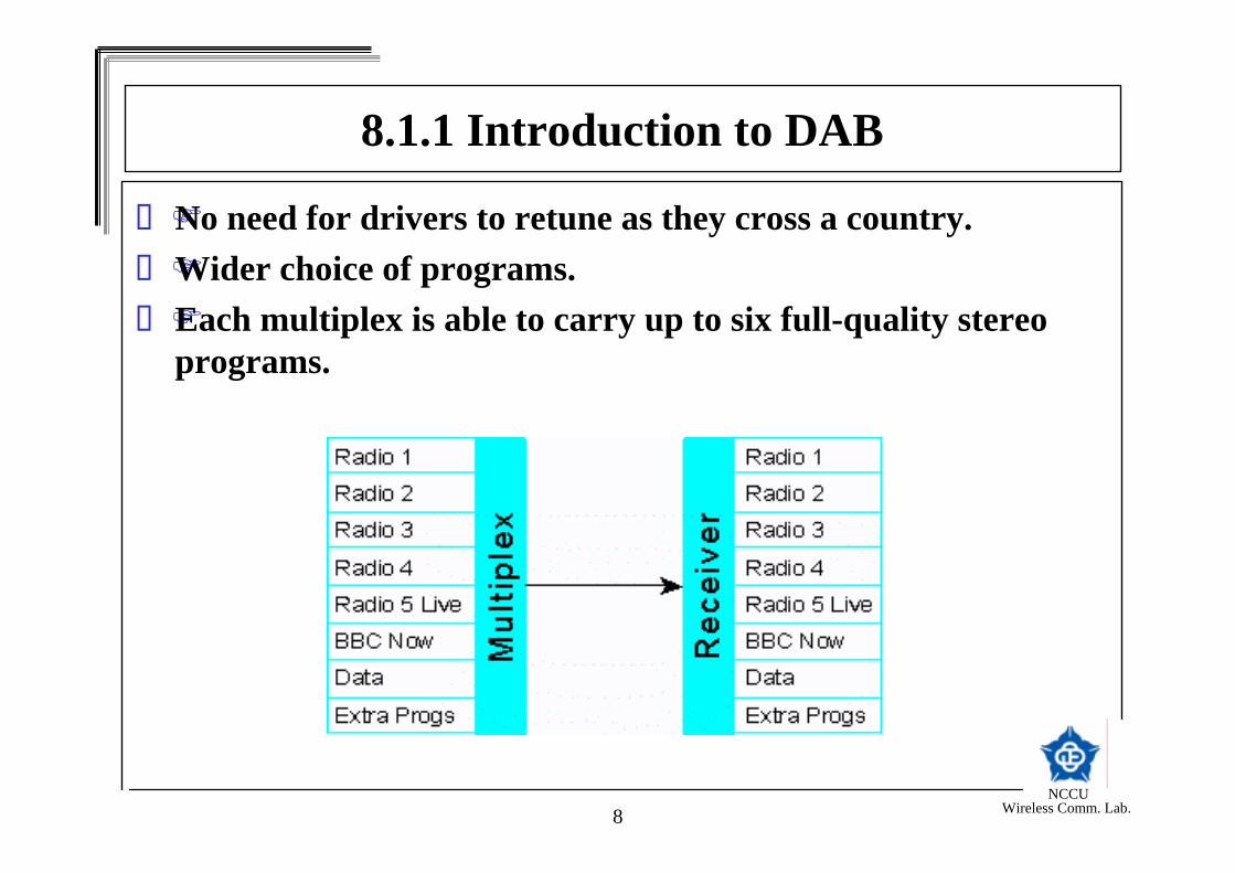
No need for drivers to retune as they cross a country.Wider choice of programs.Each multiplex is able to carry up to six full-quality stereo programs.
8.1.1 Introduction to DAB
NCCU Wireless Comm. Lab.9
8.1.1 Introduction to DAB

NCCU Wireless Comm. Lab.10
DAB can carry text and images as well as sound.All but the smallest will be able to display at least two 16-character lines of text.Selection by name or programme type.Enabling broadcasters to transmit programme-associated data (PAD) such as album title, song lyrics, or contact details.DAB can be transmitted at lower power than today's FM and AM services without loss of coverage
8.1.1 Introduction to DAB

NCCU Wireless Comm. Lab.11
DAB combines two advanced digital technologies to achieve robust and spectrum-efficient transmission of high-quality audio and other data.DAB uses the MPEG Audio Layer II system to achieve a compression ratio of 7:1 without perceptible loss of quality.The signal is then encoded at a bit rate of 8-384 kbit/s, depending on the desired sound quality and the available bandwidth.
8.1.1 Introduction to DAB

NCCU Wireless Comm. Lab.12
Signal is individually error protected and labeled prior to multiplexing. Independent data services are similarly encoded.The Coded Orthogonal Frequency Division Multiplex (COFDM) technology is used for transmission.2.3 million bits of the multiplexed signal in time and across 1,536 distinct frequencies within the 1.5 MHz band.
8.1.1 Introduction to DAB
NCCU Wireless Comm. Lab.13
An conventional FM network must use different frequencies in each area. In a DAB network, all transmitters operate on a single frequency. Such a Single Frequency Network (SFN) makes DAB's use of the radio spectrum over three times more efficient than conventional FM.DAB is designed for terrestrial, cable and for future satellite broadcasts
8.1.1 Introduction to DAB

NCCU Wireless Comm. Lab.14
Technical characteristics frequency range up to 20 kHz 48 kHz sampling rate; 18-bit resolution 4 audio modes: mono, stereo, dual channel, and joint stereo bit rates from 32 kbit/s mono to 384 kbit/s stereophonic programme audio frame 24 ms corresponding 1152 PCM audio samples digital I/O conform AES/EBU standard 2 kbit/s (bytes of data per frame) for Program Associated Data (PAD)
8.1.1 Introduction to DAB

NCCU Wireless Comm. Lab.15
Transmission system Radio signal is normally distorted by
physical conditions multipath propagation
Interference can be avoided by using COFDMCOFDM with error detection and correction provides a digital transparent channel allowing transmission of a stereo program or any other data.Programs are divided into a total of 1536 carrier frequencies bandwidth 1.5 Mhz.
8.1.1 Introduction to DAB

NCCU Wireless Comm. Lab.16
8.1.2 DAB System OverviewAudio, control information, and digital data service are multiplexed together to form OFDM signal on the air.The audio is encoded by MPEG Audio Layer II.The control information is used to interpret the configuration of the Main Service Channel (MSC).
NCCU Wireless Comm. Lab.17
The control information is transmitted over the Fast Information Channel (FIC), which is made up of Fast Information Block (FIB).See the block diagram shown below.
8.1.2 DAB System Overview
NCCU Wireless Comm. Lab.18
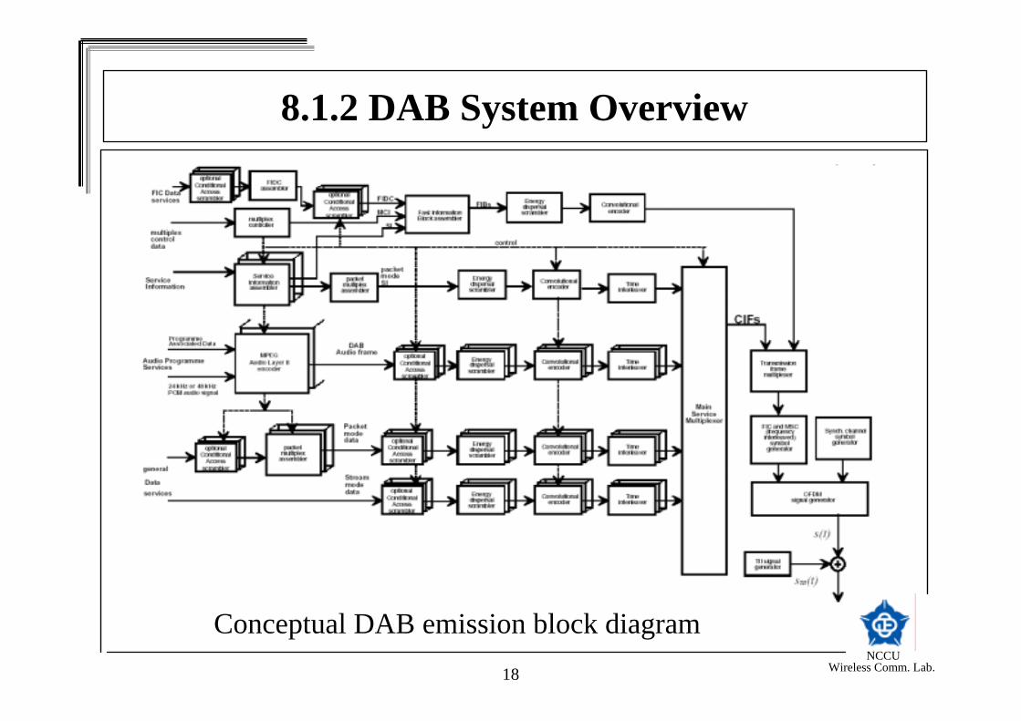
Conceptual DAB emission block diagram
8.1.2 DAB System Overview

NCCU Wireless Comm. Lab.19
8.1.3 DAB Channel Coding
Channel coding is based on a convolutional code with constraint length 7.Punctured convolutional coding allows Unequal Error Protection (UEP).Several convolutional coded stream are then combined and mapped into OFDM symbols.

NCCU Wireless Comm. Lab.20
8.1.3 DAB Channel CodingThe mother code generates from the vector a codeword
for
10)( −
=Iia
50,3,2,1,0 )},,,{( +
=Iiiiii xxxx
6532,3
641,2
6321,1
6532,0
−−−−
−−−
−⊕−−−
−−−−
⊕⊕⊕⊕=
⊕⊕⊕=
⊕⊕⊕=
⊕⊕⊕⊕=
iiiiii
iiiii
iiiiii
iiiiii
aaaaaxaaaax
aaaaaxaaaaax
5,...,2,1,0 += Ii

NCCU Wireless Comm. Lab.21
8.1.3 DAB Channel CodingConvolutional Encoder
NCCU Wireless Comm. Lab.22
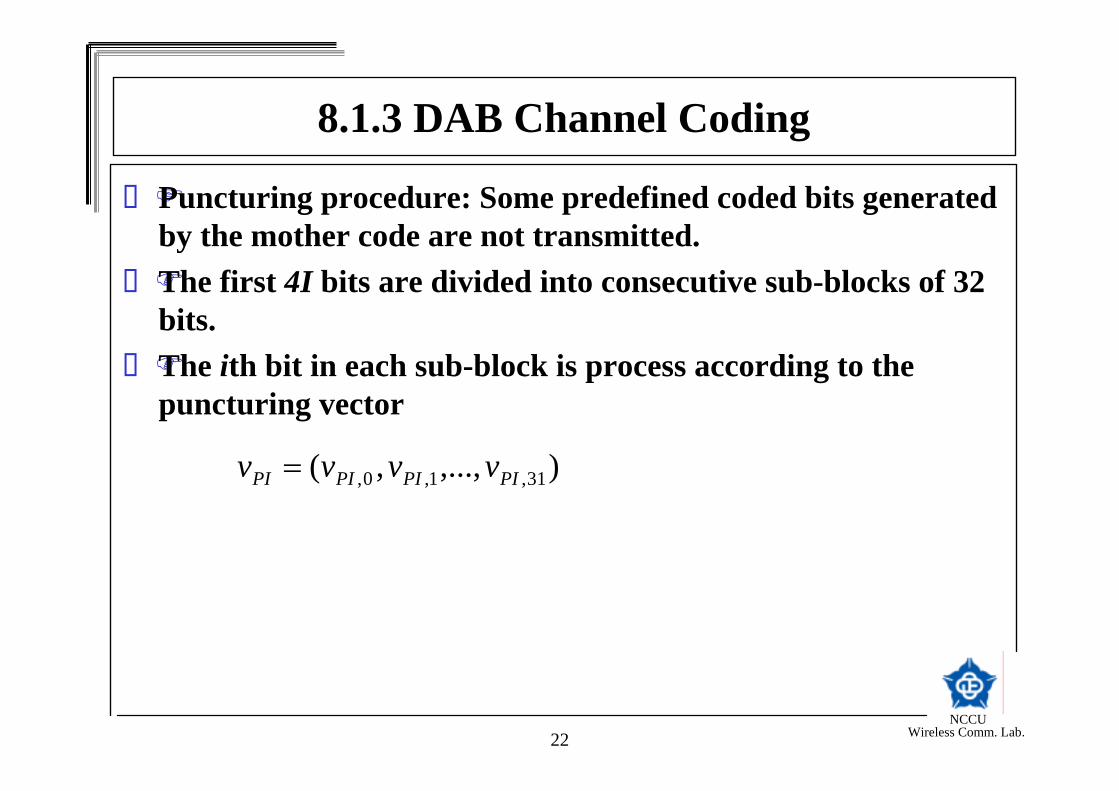
Puncturing procedure: Some predefined coded bits generated by the mother code are not transmitted.The first 4I bits are divided into consecutive sub-blocks of 32 bits.The ith bit in each sub-block is process according to the puncturing vector
),...,,( 31,1,0, PIPIPIPI vvvv =
8.1.3 DAB Channel Coding

NCCU Wireless Comm. Lab.23
8.1.3 DAB Channel CodingFor , the corresponding bit shall be taken out of the sub-block and shall not be transmitted.For , the corresponding bit shall be retrained in the sub-block and shall be transmitted. There are total 24 possible puncturing vectors so the rate of the punctured convolutional code varies from 8/9 to ¼.
0, =iPIv
1, =iPIv
NCCU Wireless Comm. Lab.24
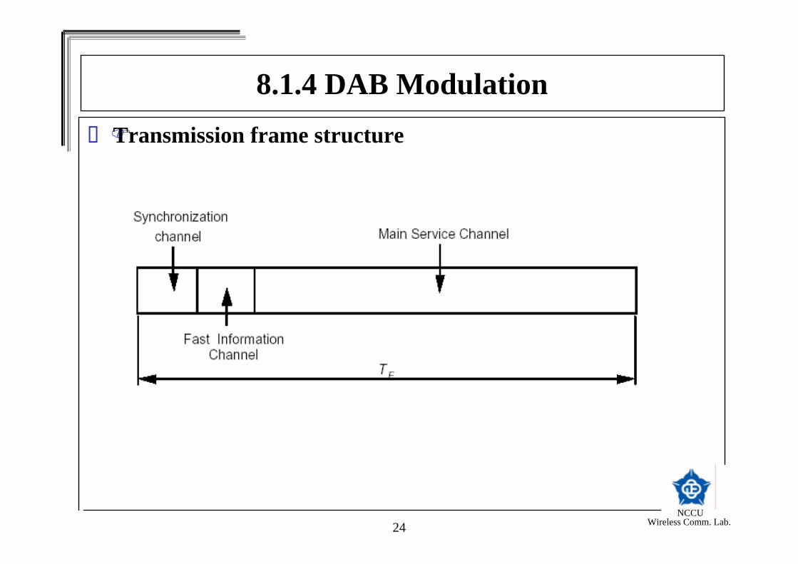
8.1.4 DAB ModulationTransmission frame structure

NCCU Wireless Comm. Lab.25
Four transmission modes are definedEach transmission frame is divided into a sequence of OFDM symbols.The first OFDM symbol of the transmission frame shall be the Null symbol of duration TNULL. The remaining part is OFDM symbols of duration TS.
8.1.4 DAB Modulation
NCCU Wireless Comm. Lab.26
8.1.4 DAB Modulation
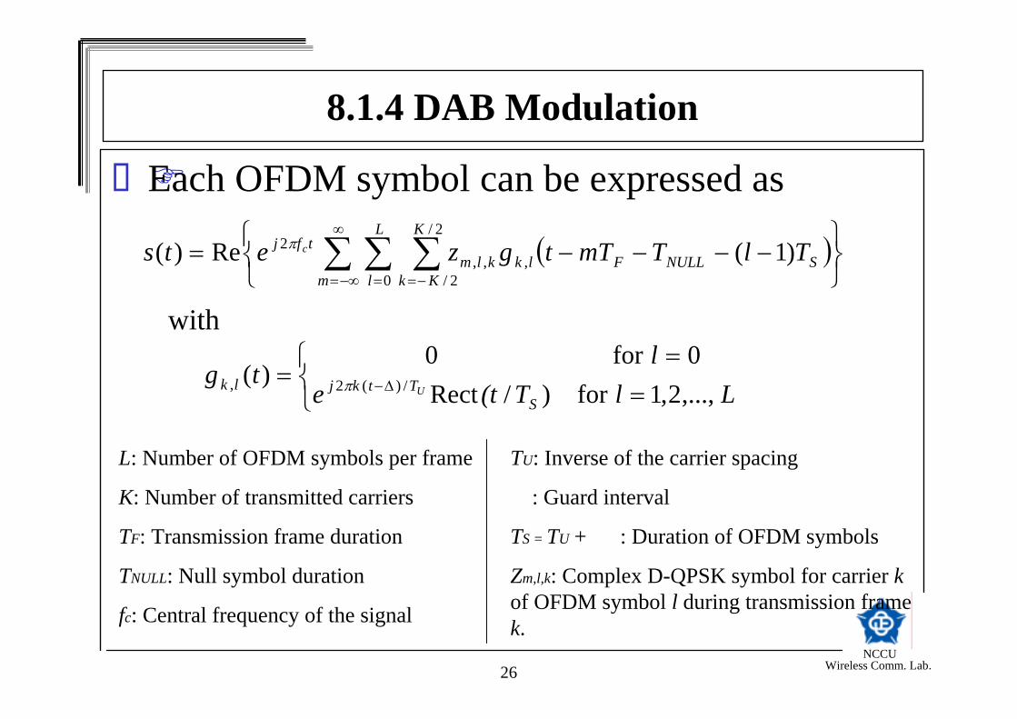
Each OFDM symbol can be expressed as
( )
−−−−= ∑ ∑ ∑∞
−∞= = −=m
L
l
K
KkSNULLFlkklm
tfj TlTmTtgzets c
0
2/
2/,,,
2 )1(Re)( π
with
==
= ∆− LlT(tel
tgS
Ttkjlk U ,...,2,1for )/Rect0for 0
)( /)(2, π
L: Number of OFDM symbols per frame
K: Number of transmitted carriers
TF: Transmission frame duration
TNULL: Null symbol duration
fc: Central frequency of the signal
TU: Inverse of the carrier spacing
Δ: Guard interval
TS = TU + Δ : Duration of OFDM symbols
Zm,l,k: Complex D-QPSK symbol for carrier kof OFDM symbol l during transmission frame k.

NCCU Wireless Comm. Lab.27
Definition of the parameters for transmission modes I,II,III, and IV.
8.1.4 DAB Modulation

NCCU Wireless Comm. Lab.28
Conceptual block diagram of the generation of the main signal
8.1.4 DAB Modulation

NCCU Wireless Comm. Lab.29
Synchronization Channel: the first two OFDM symbolsDuring the time interval [0,TNULL], the main signal s(t) shall be equal to zero.The second OFDM symbol is the phase reference symbol defined by the value of zl,k for l=1:
=≤<<≤−
=0for 0
2/0 and 02/for ,1 k
KkkKez
kj
k
ϕ
8.1.4 DAB Modulation

NCCU Wireless Comm. Lab.30
8.1.4 DAB Modulation
The values of shall be obtained from the following formulae
The values of the parameter as a function of indices i and j are specified in the standard
kϕ
)(2 ', nh kkik += −πϕ
jih ,

NCCU Wireless Comm. Lab.31
8.1.5 Channel for DAB OFDM SystemAssume that there are M stations that transmit synchronous OFDM frame s(t).
)(ts
)(ts
)(1 th
)(2 th
)(thM
)(*)()(1
thtstr j
M
j∑=
=
receiver
)(ts

NCCU Wireless Comm. Lab.32
8.1.5 Channel for DAB OFDM SystemThe signal from the station j propagates to the receiver. The received signal from the jth station can be expressed as
where * denotes the convolution and hj(t) is the channel impulse response from station j to the receiver.
The overall received signal from all stations can be expressed as
)()()( thtstr jj ∗=
∑
∑∑
=
==
∗=
∗==
M
jj
M
jj
M
jj
thts
thtstrtr
1
11
)()(
)()()()(

NCCU Wireless Comm. Lab.33
8.1.5 Channel for DAB OFDM SystemNow we may define the overall channel impulse response as
The received signal can be expressed as
No inter-symbol interference (ISI) if the spreading of h(t) is less then the guard interval.
∑=
=M
jj thth
1
)()(
)()()( thtstr ∗=

NCCU Wireless Comm. Lab.34
8.1.6 Receiver for DAB OFDM SystemTuning (frequency) accuracy required is 5%.Robust frequency tracking is required.Fast channel and timing tracking to overcome the rapidly change condition.

NCCU Wireless Comm. Lab.35
Block diagram of DAB receiver
8.1.6 Receiver for DAB OFDM System
NCCU Wireless Comm. Lab.36
8.2 HDTV-Digital Video Broadcasting (DVB)

NCCU Wireless Comm. Lab.37
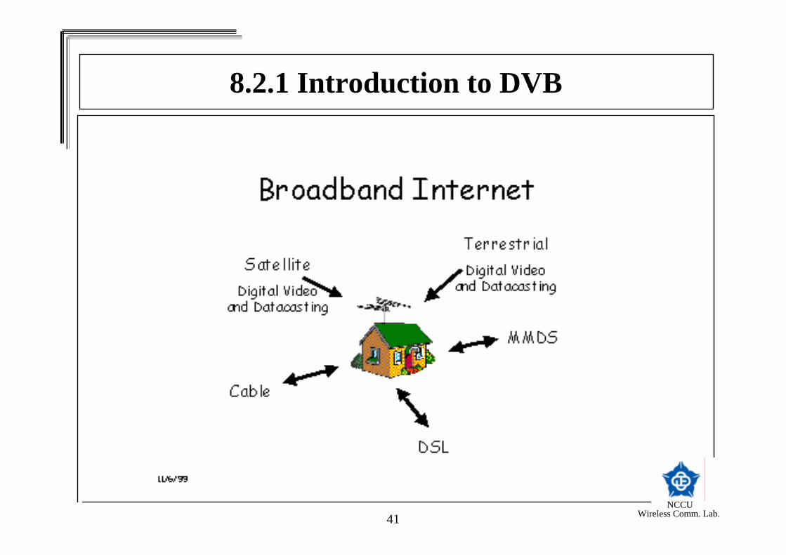
8.2.1 Introduction to DVBAudio and Video-centricVery large files transmission.Quality of service issues.
Guaranteed bandwidthJitterDelay
Large, scalable audienceBroadband downstream, narrowband upSatellite: DVB-STerrestrial: ATSC, DVB-T

NCCU Wireless Comm. Lab.38
European standard for transmission of digital TV via satellite, cable or terrestrial
DVB-S (satellite)QPSK – Quadrature Phase-Shift Keying
DVB-T (terrestrial)COFDM – Coded Orthogonal Frequency Division Multiplexing
MPEG-2 compression and transport streamSupport for multiple, encrypted program stream.
8.2.1 Introduction to DVB

NCCU Wireless Comm. Lab.39
8.2.1 Introduction to DVB

NCCU Wireless Comm. Lab.40
8.2.1 Introduction to DVB
Digital Video Combines Traditional and Interactive Content and Applications
Interactive
Enhanced DVDMovies/musicInteractive gamesVideophoneCreating and
sharing documentsOnline E-commerce
Traditional
FilmTVMusicBooksMagazinesBoard games
NCCU Wireless Comm. Lab.41
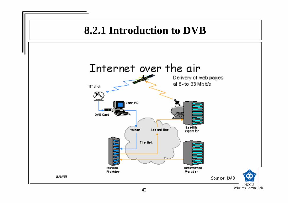
8.2.1 Introduction to DVB
NCCU Wireless Comm. Lab.42
8.2.1 Introduction to DVB

NCCU Wireless Comm. Lab.43
8.2.1 Introduction to DVB

NCCU Wireless Comm. Lab.44
8.2.2 DVB System OverviewMPEG-2 source coding and multiplexingOuter coding (Reed-Solomon code)Outer interleaving (convolutional interleaving)Inner coding (punctured convolutional code)Inner interleaving Mapping and modulation (BPSK,QPSK,16-QAM, 64-QAM)Transmission – Orthogonal Frequency Division Multiplexing (OFDM)
NCCU Wireless Comm. Lab.45
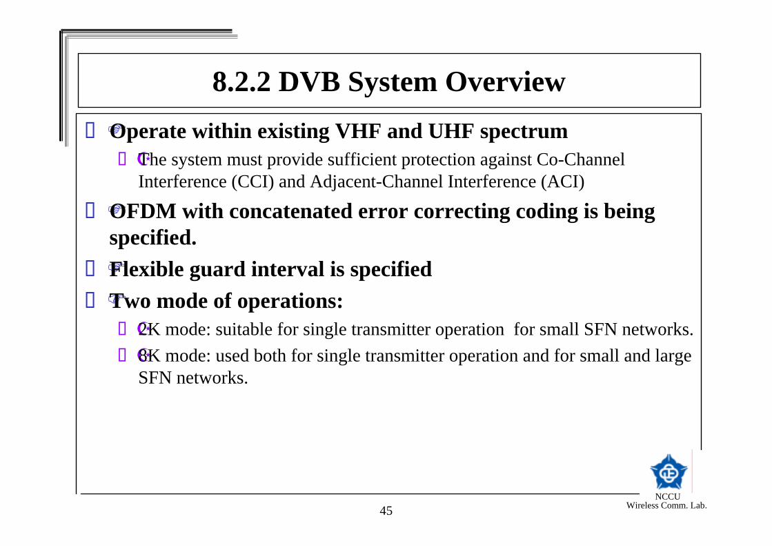
Operate within existing VHF and UHF spectrumThe system must provide sufficient protection against Co-Channel Interference (CCI) and Adjacent-Channel Interference (ACI)
OFDM with concatenated error correcting coding is being specified.Flexible guard interval is specifiedTwo mode of operations:
2K mode: suitable for single transmitter operation for small SFN networks.8K mode: used both for single transmitter operation and for small and large SFN networks.
8.2.2 DVB System Overview

NCCU Wireless Comm. Lab.46
Multi-level QAM modulationDifferent inner code rates (punctured convolutional code)MPEG stream is separated into
High-priority streamLow-priority stream
Unequal Error Protection (UEP)High-priority stream is high-level protected.Low-priority stream is low-level protected.
8.2.2 DVB System Overview

NCCU Wireless Comm. Lab.47
8.2.2 DVB System OverviewFunctional block diagram of the DVB transmitter

NCCU Wireless Comm. Lab.48
8.2.3 Channel Coding and Modulation
Transport multiplex adaptation and randomization (scrambler)

NCCU Wireless Comm. Lab.49
The total packet length of the MPEG-2 MUX packet is 188 bytes.The data of the input MPEG-2 multiplex shall be randomized with the above circuit.
8.2.3 Channel Coding and Modulation

NCCU Wireless Comm. Lab.50
Outer coding and outer interleavingRS (204,188) shortened code from RS (255,239) is adopted.
8.2.3 Channel Coding and Modulation

NCCU Wireless Comm. Lab.51
8.2.3 Channel Coding and Modulation Convolutional interleaving
Convolutional byte-wise interleaving with depth I=12

NCCU Wireless Comm. Lab.52
Inner codingConvolutional code of rate ½ with 64 states.Generator polynomial G1=171OCT and G2=133OCT
8.2.3 Channel Coding and Modulation
NCCU Wireless Comm. Lab.53
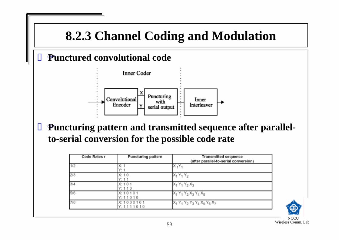
8.2.3 Channel Coding and ModulationPunctured convolutional code
Puncturing pattern and transmitted sequence after parallel-to-serial conversion for the possible code rate

NCCU Wireless Comm. Lab.54
8.2.3 Channel Coding and ModulationInner interleaving
Bit-wise interleaving followed by symbol interleaving .Both the bit-wise interleaving and the symbol interleaving processes are block-based.
Define a mapping (demultiplexing) of the input bits xdi onto the output bits be,do
In non-hierarchical mode:
vdivdivvdidi bx )div()],2/(mod)([2)2/)(div]((mod)[ +=

NCCU Wireless Comm. Lab.55
8.2.3 Channel Coding and ModulationIn non-hierarchical mode:
High-priority input
Low-priority input
2)div(,2(mod)' dididi bx =
)2)(div(,2)]2/)2(mod)(([2)2/)2)((div)](2(mod)(['' −+−+−−= vdivdivvdidi bx
NCCU Wireless Comm. Lab.56
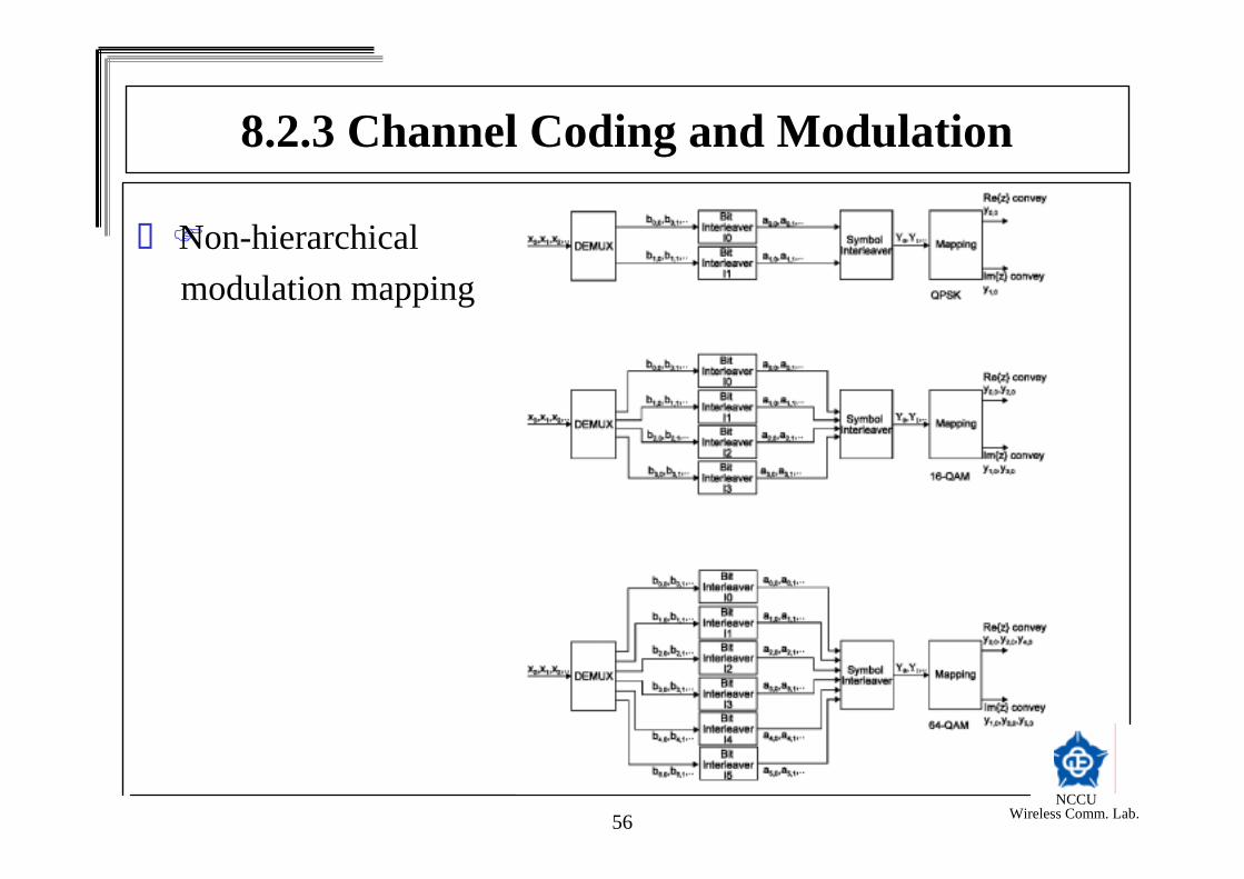
Non-hierarchical modulation mapping
8.2.3 Channel Coding and Modulation

NCCU Wireless Comm. Lab.57
Hierarchical modulation mapping
8.2.3 Channel Coding and Modulation

NCCU Wireless Comm. Lab.58
8.2.3 Channel Coding and ModulationBit interleaver
For each bit interleaver, the input bit vector is defined by
where e ranges from 0 to v-1.
The interleaved output vector
is defined by
where He(w) is a permutation function which is different for each interleaver.
),...,,,()( 125,2,1,0, eeee bbbbeB =
),...,,,()( 125,2,1,0, eeee aaaaeA =
)(,, wHewe eba =

NCCU Wireless Comm. Lab.59
8.2.3 Channel Coding and ModulationSymbol interleaver
Map v bit words onto the 1512 (2K mode) or 6048 (8K mode) active carriers per OFDM symbol.To spread consecutive poor channels into random-like fading.Symbol interleaver address generation schemes are employed for the symbol interleaver.

NCCU Wireless Comm. Lab.60
8.2.3 Channel Coding and ModulationSignal constellations and mapping
OFDM transmissionAll data carries in one OFDM frame are modulated using either QPSK, 16-QAM, 64QAM, non-uniform 16-QAM or non-uniform 64-QAM.The non-uniform signal constellation provides Unequal Error Protection (UEP).
NCCU Wireless Comm. Lab.61
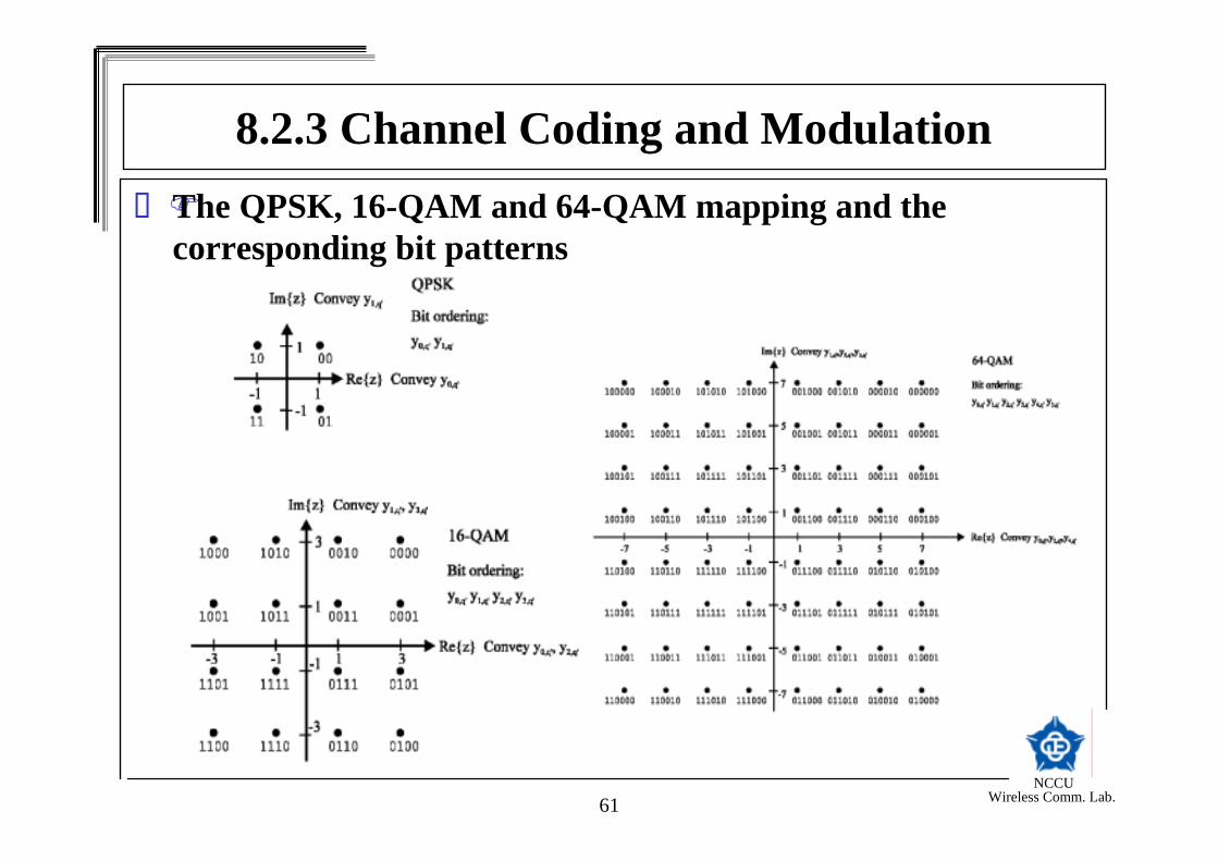
8.2.3 Channel Coding and ModulationThe QPSK, 16-QAM and 64-QAM mapping and the corresponding bit patterns

NCCU Wireless Comm. Lab.62
8.2.3 Channel Coding and ModulationThe Non-uniform 16-QAM and 64-QAM mappings
NCCU Wireless Comm. Lab.63
8.2.3 Channel Coding and ModulationOFDM frame structure
Each frame has duration TF
Consists of 68 OFDM symbolsFour frames constitute one super-frameEach OFDM symbol contains K=6817 (8K mode) or K=1705 (2K mode) carriersThe duration of each OFDM symbol is TS =TU+Δ where Δ is the guard interval and TU is the useful part.The symbols in an OFDM frame are numbered from 0 to 67Scattered pilot cells (carrier)Continual pilot carriersTPS carriers
NCCU Wireless Comm. Lab.64
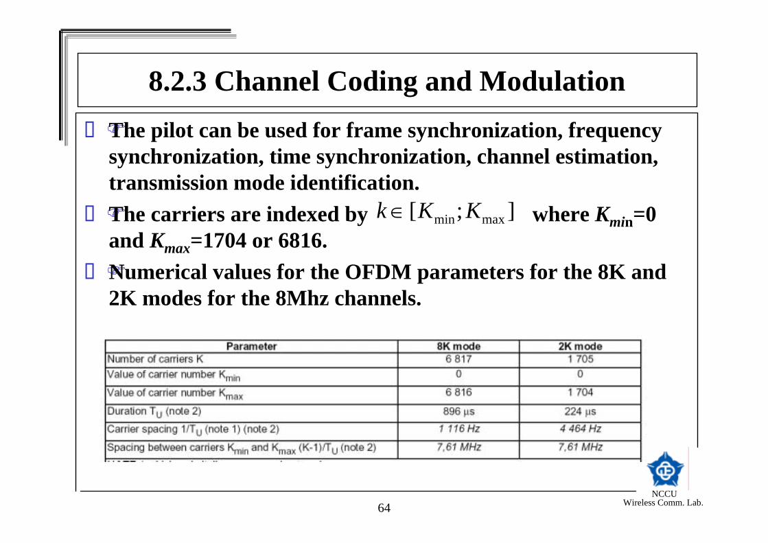
8.2.3 Channel Coding and ModulationThe pilot can be used for frame synchronization, frequency synchronization, time synchronization, channel estimation, transmission mode identification.The carriers are indexed by where Kmin=0 and Kmax=1704 or 6816. Numerical values for the OFDM parameters for the 8K and 2K modes for the 8Mhz channels.
];[ maxmin KKk ∈

NCCU Wireless Comm. Lab.65
The emitted signal is described by the following expression:
×+×+≤≤××+=
×=
××−×−∆−
∞
= = =∑∑ ∑
elseTmltTmlet
tcets
SS
TmTltTkj
klm
m l
K
Kkklmklm
tfj
ssU
c
0)168()68()(
)(Re)(
)68('2
,,
0
67
0,,,,
2max
min
π
π
ψ
ψ
k: carrier number
l: OFDM symbol number
m: frame number
K: number of transmitted carriers
TS: symbol duration
TU: inverse of the carrier spacing
Δ: Guard interval
fc: central frequency of the RF signal
k’: k’=k-(Kmax - Kmin)/2
cm,l,k: complex symbol for carrier k of data symbol number l in frame number m
8.2.3 Channel Coding and Modulation

NCCU Wireless Comm. Lab.66
Duration of symbol part for the guard intervals for 8Mhz channel
8.2.3 Channel Coding and Modulation

NCCU Wireless Comm. Lab.67
8.2.3 Channel Coding and ModulationReference signal
Various cells within the OFDM frame are modulated with referenceinformation whose transmitted values is known to the receiverThe value of the pilot information is derived from a Pseudo Random Binary Sequence (PRBS)Two kinds of pilots: scattered pilot and continual pilot
NCCU Wireless Comm. Lab.68
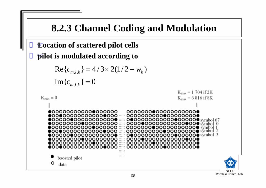
8.2.3 Channel Coding and ModulationLocation of scattered pilot cellspilot is modulated according to
0}Im{)2/1(23/4}Re{
,,
,,
=
−×=
klm
kklm
cwc

NCCU Wireless Comm. Lab.69
8.2.3 Channel Coding and ModulationLocation of continual pilot carriersPilot is modulated according to
0}Im{)2/1(23/4}Re{
,,
,,
=
−×=
klm
kklm
cwc

NCCU Wireless Comm. Lab.70
8.2.3 Channel Coding and ModulationTransmission Parameter Signaling (TPS)
The TPS carriers are used for the purpose of signaling parameters related to the transmission scheme.The TPS is transmitted in parallel on 17 TPS carriers for 2K mode and on 68 carriers for the 8K mode.

NCCU Wireless Comm. Lab.71
8.2.3 Channel Coding and ModulationThe TPS carriers convey information on:
a) Modulation of the QAM constellation patternb) Hierarchy informationc) Guard intervald) Inner code ratee) 2K or 8K transmission modef) Frame number in a super-frameg) Cell identification.

NCCU Wireless Comm. Lab.72
8.3 Wireless LAN Networks
NCCU Wireless Comm. Lab.73
8.3.1 Introduction to Wireless LAN NetworksIEEE 802.11 - The first international standard for WLAN, 1997.
Infrared (IR) baseband PHY (1Mbps, 2Mbps)Frequency hopping spread spectrum (FHSS) radio in 2.4GHz band (1Mbps, 2Mbps)Direct sequence spread spectrum (DSSS) radio in the 2.4GHz band (1Mbps, 2Mbps)
IEEE 802.11a, 19995GHz bandOrthogonal frequency division multiplexing (OFDM)6Mbps to 54Mbps

NCCU Wireless Comm. Lab.74
IEEE 802.11g(802.11b + 80211a) operating at 2.4GHz bandERP-DSS/CCK: IEEE 802.11b-1999ERP-OFDM: IEEE 802.11a-1999PBCC (optional)CCK-OFDM (optional)
IEEE 802.11h/D2.2, September 2002Radar detection in 5GHz bandRegulatory (ETSI EN 301 893 v.1.2.1)Power control
8.3.1 Introduction to Wireless LAN Networks

NCCU Wireless Comm. Lab.75
Typical Wireless System
8.3.1 Introduction to Wireless LAN Networks
NCCU Wireless Comm. Lab.76
8.3.2 Indoor EnvironmentDelay Spread - refection of RF signal from wall, furniture, etc.Path lossInterference - microwave oven, Bluetooth, cordless phone, etc. Statistic channel model for WLAN

NCCU Wireless Comm. Lab.77
Typical Indoor Environment
8.3.2 Indoor Environment

NCCU Wireless Comm. Lab.78
8.3.2 Indoor EnvironmentDelay Spread

NCCU Wireless Comm. Lab.79
Typical Measurement Results I - 1 m away from the transmitter
8.3.2 Indoor Environment

NCCU Wireless Comm. Lab.80
8.3.2 Indoor EnvironmentTypical Measurement Results II - 10m, 8m, and 13.5m away from the transmitter
NCCU Wireless Comm. Lab.81
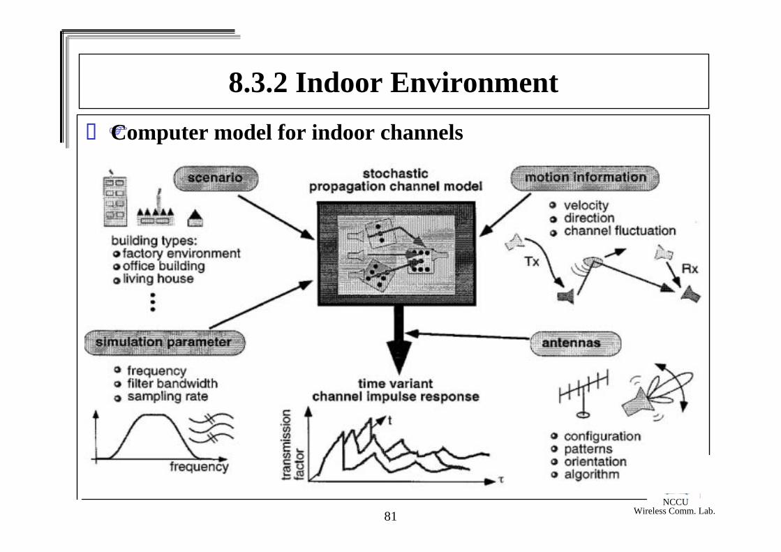
8.3.2 Indoor EnvironmentComputer model for indoor channels
NCCU Wireless Comm. Lab.82
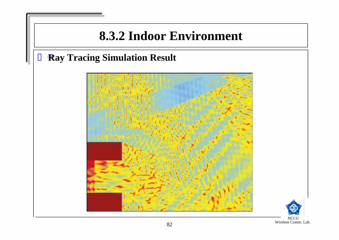
8.3.2 Indoor EnvironmentRay Tracing Simulation Result

NCCU Wireless Comm. Lab.83
8.3.3 Statistic Channel Model for WLANThis channel model was agreed to be a baseline model for comparison of modulation methods. Simple mathematical description and in the possibility to vary the RMS delay spread.The channel is assumed static throughout the packet and generated independently for each packet.

NCCU Wireless Comm. Lab.84
The received signal
∑=
− +=K
knkknn whxr
0
*
where wn is the additive white Gaussian noise, xn is the transmitted signal and hk is the baseband complex impulse response
8.3.3 Statistic Channel Model for WLAN

NCCU Wireless Comm. Lab.85
Channel Impulse response
8.3.3 Statistic Channel Model for WLAN
NCCU Wireless Comm. Lab.86
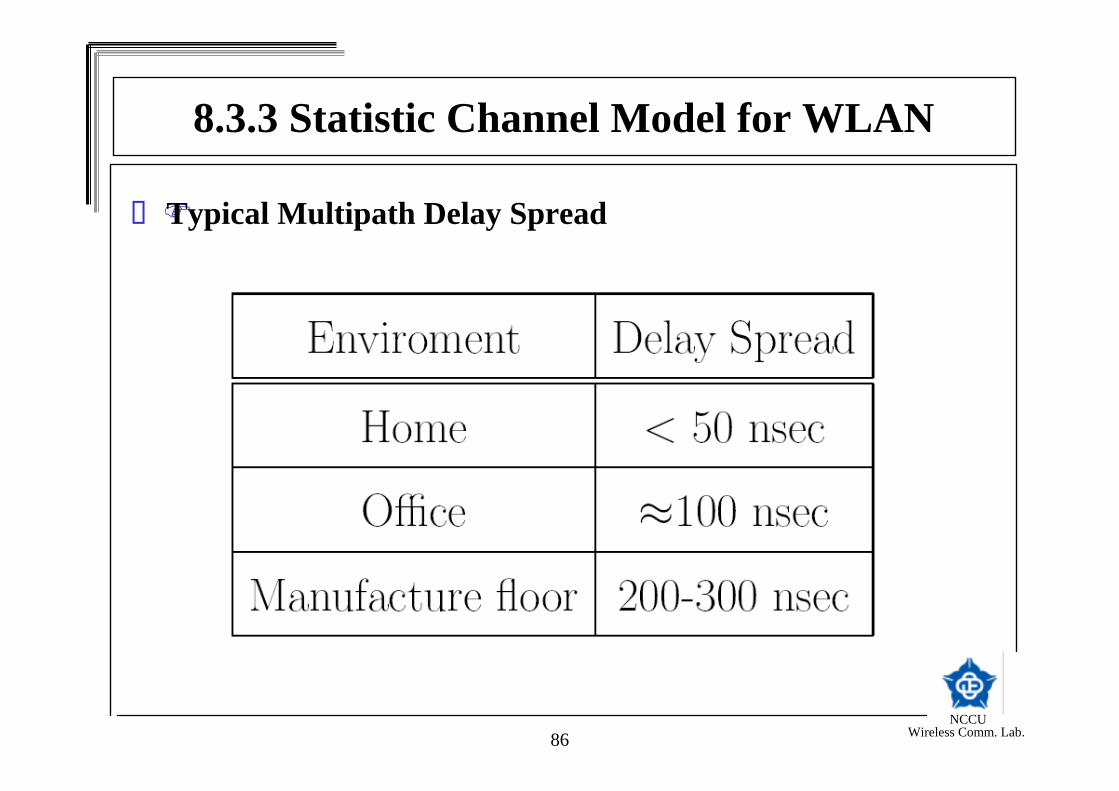
Typical Multipath Delay Spread
8.3.3 Statistic Channel Model for WLAN
NCCU Wireless Comm. Lab.87
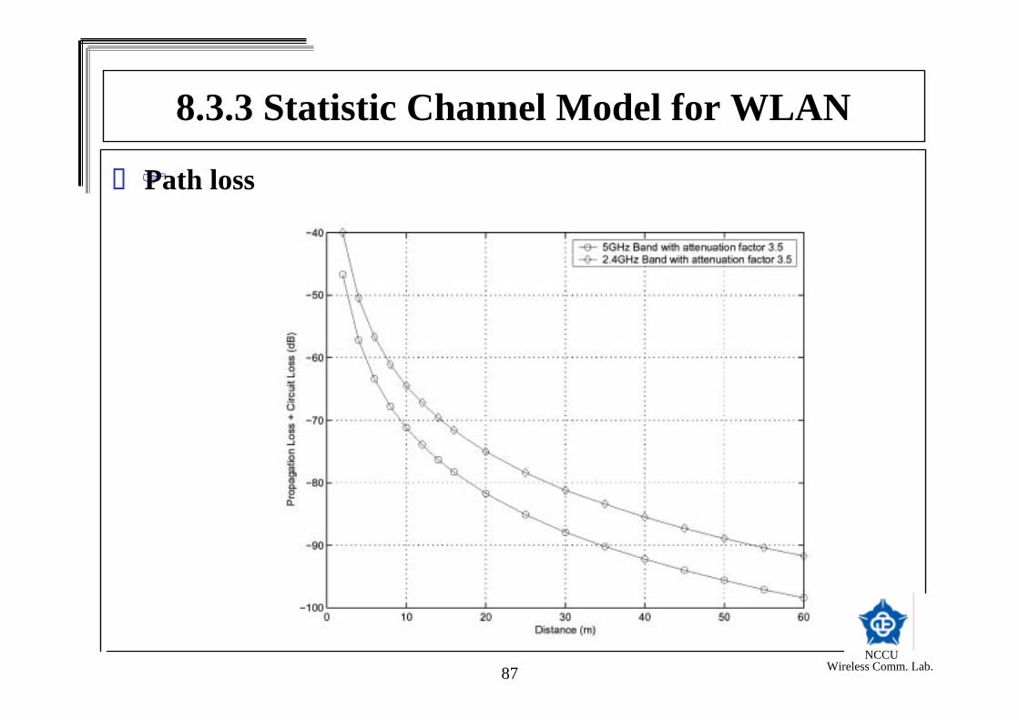
Path loss
8.3.3 Statistic Channel Model for WLAN
NCCU Wireless Comm. Lab.88
8.3.4 802.11a WLAN StandardOFDM system with punctured convolutional code.52 carriers with 4 pilot tones.Date rate from 6Mbps to 54Mbps
NCCU Wireless Comm. Lab.89
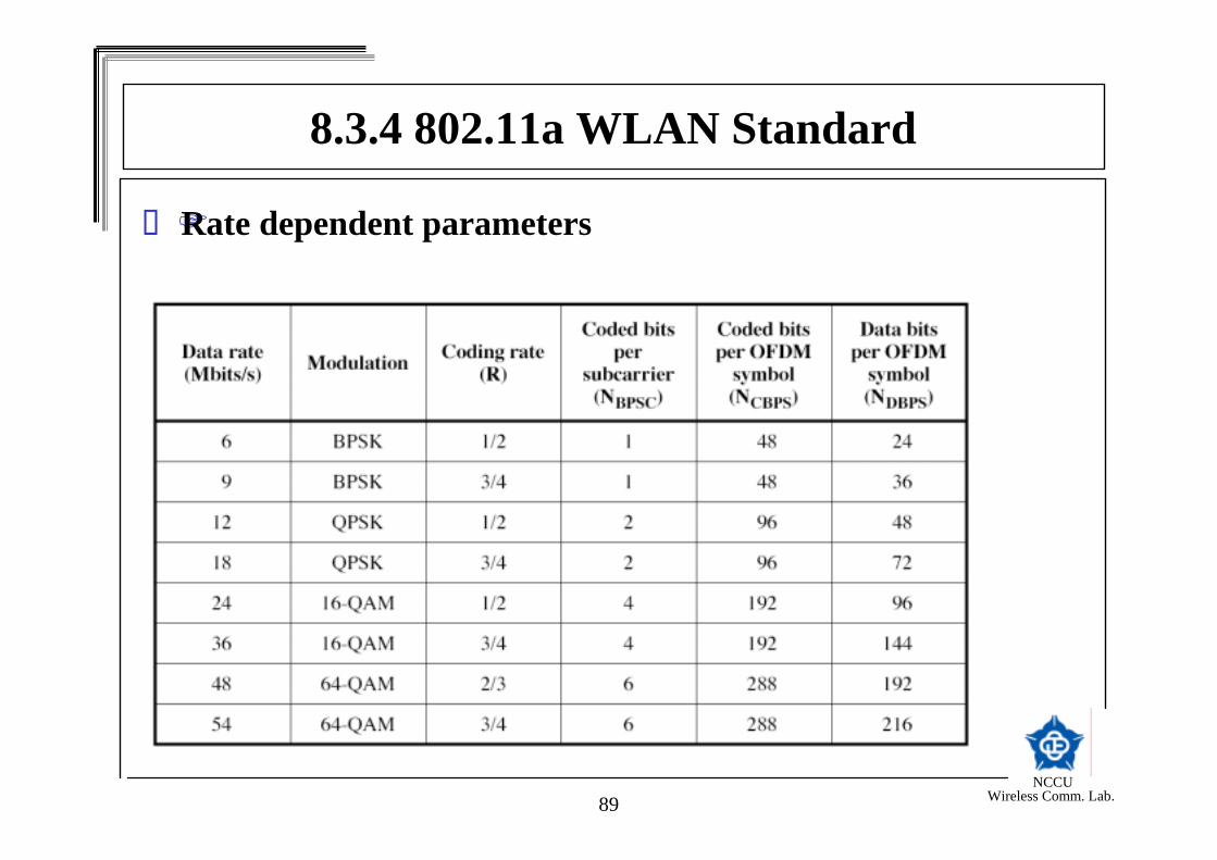
Rate dependent parameters
8.3.4 802.11a WLAN Standard

NCCU Wireless Comm. Lab.90
Timing related parameters
8.3.4 802.11a WLAN Standard

NCCU Wireless Comm. Lab.91
8.3.4 802.11a WLAN StandardTransmitter of 802.11a

NCCU Wireless Comm. Lab.92
8.3.4 802.11a WLAN StandardAll the subframes of the signal are constructed as an inverse Fourier transform of a set of coefficients, Ck , with Ck defined as data, pilots, or training symbols.
Where is a time window function defined by
∑−=
−∆=2/
2/
))(2exp()()(ST
ST
N
NkGUARDfkTSUBFRAMESUBFRAME TtkjCtwtr π
)(twT

NCCU Wireless Comm. Lab.93
8.3.4 802.11a WLAN StandardCyclic extension and window function (a) single reception and (b) two receptions
NCCU Wireless Comm. Lab.94
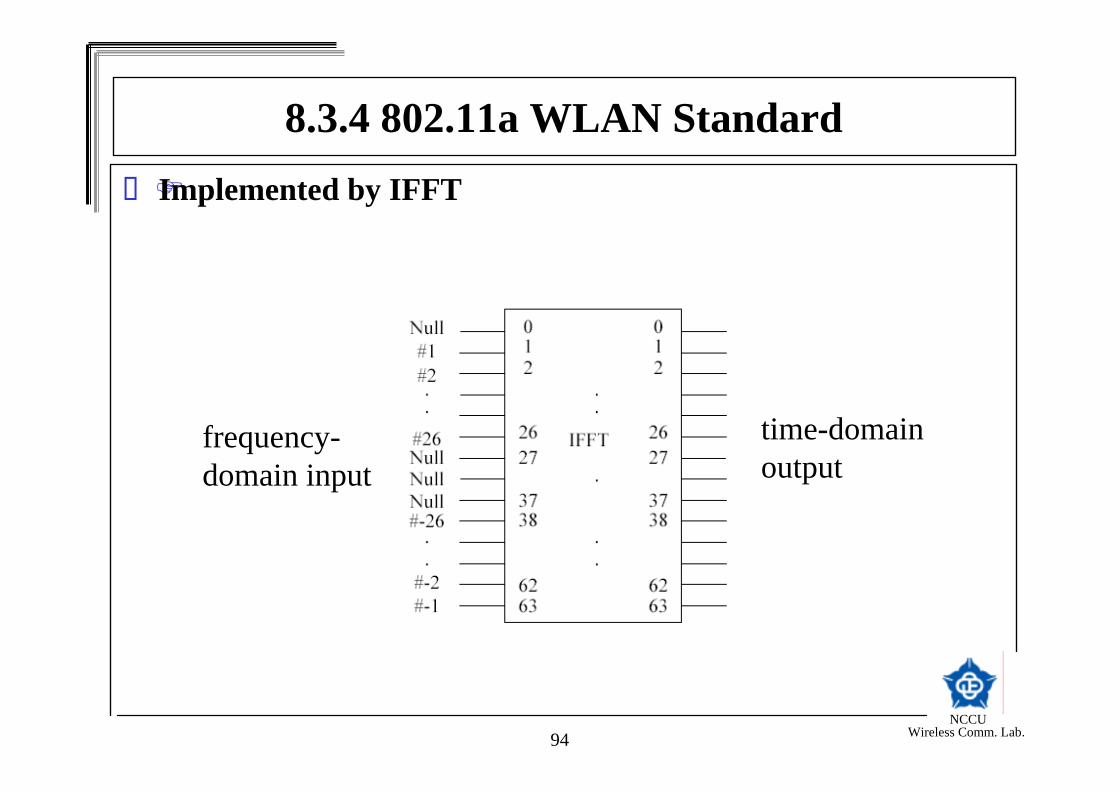
8.3.4 802.11a WLAN StandardImplemented by IFFT
frequency-domain input
time-domain output

NCCU Wireless Comm. Lab.95
OFDM packet structure
A short OFDM training symbol consists of 12 subcarriers, which are modulated by the elements of the sequence S, given by
The short training signal shall be generated according to
∑−=
∆=2/
2/
)2exp()()(ST
ST
N
NkfkTSHORTSHORT kjStwtr π
8.3.4 802.11a WLAN Standard
NCCU Wireless Comm. Lab.96
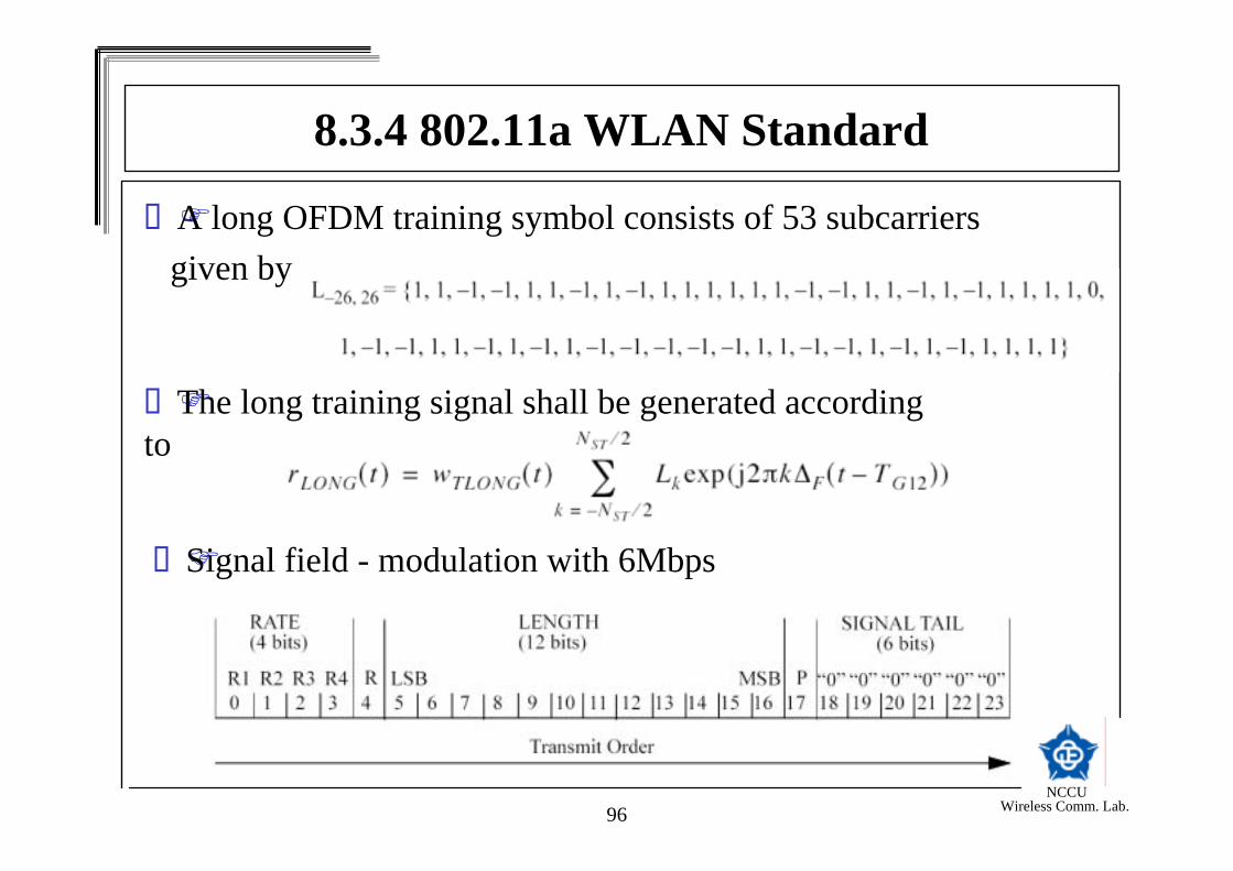
A long OFDM training symbol consists of 53 subcarriers given by
The long training signal shall be generated according to
Signal field - modulation with 6Mbps
8.3.4 802.11a WLAN Standard

NCCU Wireless Comm. Lab.97
8.3.4 802.11a WLAN StandardData field includes
Service field - scrambler initializationPSDU - carry the data to be transmitted.Tail bit field - 6 bits of zero to return the convolutional encoder to zero state.Pad bits (PAD) - zero bits.
DATA scrambler and descramblerscrambler and descrambler use the same module.
NCCU Wireless Comm. Lab.98
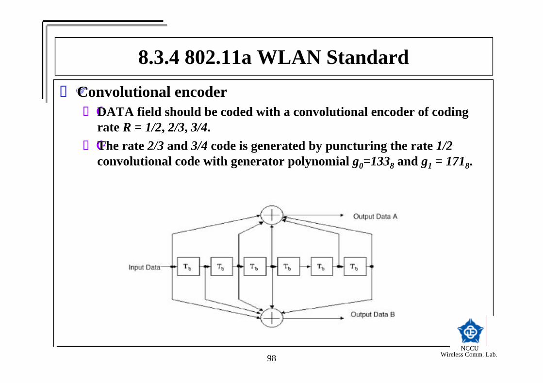
8.3.4 802.11a WLAN StandardConvolutional encoder
DATA field should be coded with a convolutional encoder of coding rate R = 1/2, 2/3, 3/4.The rate 2/3 and 3/4 code is generated by puncturing the rate 1/2convolutional code with generator polynomial g0=1338 and g1 = 1718.

NCCU Wireless Comm. Lab.99
8.3.4 802.11a WLAN StandardPuncturing Procedure for rate 3/4 code

NCCU Wireless Comm. Lab.100
8.3.4 802.11a WLAN StandardPuncturing Procedure for rate 2/3 code

NCCU Wireless Comm. Lab.101
8.3.4 802.11a WLAN StandardData interleaving
All encoded data bits shall be interleaved by a block interleaver with block size corresponding to the number of bits in a single OFDM symbol.The interleaver is defined by a two-step permutation.The coded bits are interleved in the transmitter and deinterleaved in the receiver.The purpose of the interleaver is to prevent long burst of errors.

NCCU Wireless Comm. Lab.102
8.3.4 802.11a WLAN StandardSubcarrier modulation mapping
BPSK, QPSK, 16-QAM, or 64-QAM is employed depending on the rate required.The interleaved date is grouped into 1, 2, 4, or 6 bits and mapped to BPSK, QPSK, 16-QAM, or 64-QAM constellation points.

NCCU Wireless Comm. Lab.103
8.3.4 802.11a WLAN StandardSignal constellations - BPSK, QPSK, and 16-QAM

NCCU Wireless Comm. Lab.104
8.3.4 802.11a WLAN Standard• Signal constellations - 64-QAM
NCCU Wireless Comm. Lab.105
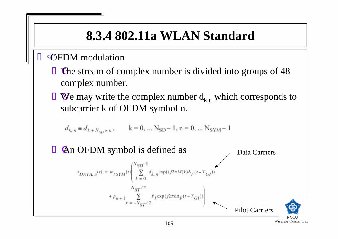
8.3.4 802.11a WLAN StandardOFDM modulation
The stream of complex number is divided into groups of 48 complex number. We may write the complex number dk,n which corresponds to subcarrier k of OFDM symbol n.
An OFDM symbol is defined as Data Carriers
Pilot Carriers
NCCU Wireless Comm. Lab.106
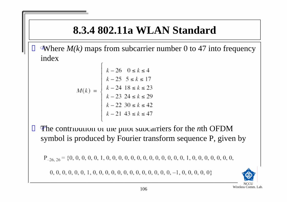
8.3.4 802.11a WLAN StandardWhere M(k) maps from subcarrier number 0 to 47 into frequency
index
The contribution of the pilot subcarriers for the nth OFDM symbol is produced by Fourier transform sequence P, given by
NCCU Wireless Comm. Lab.107
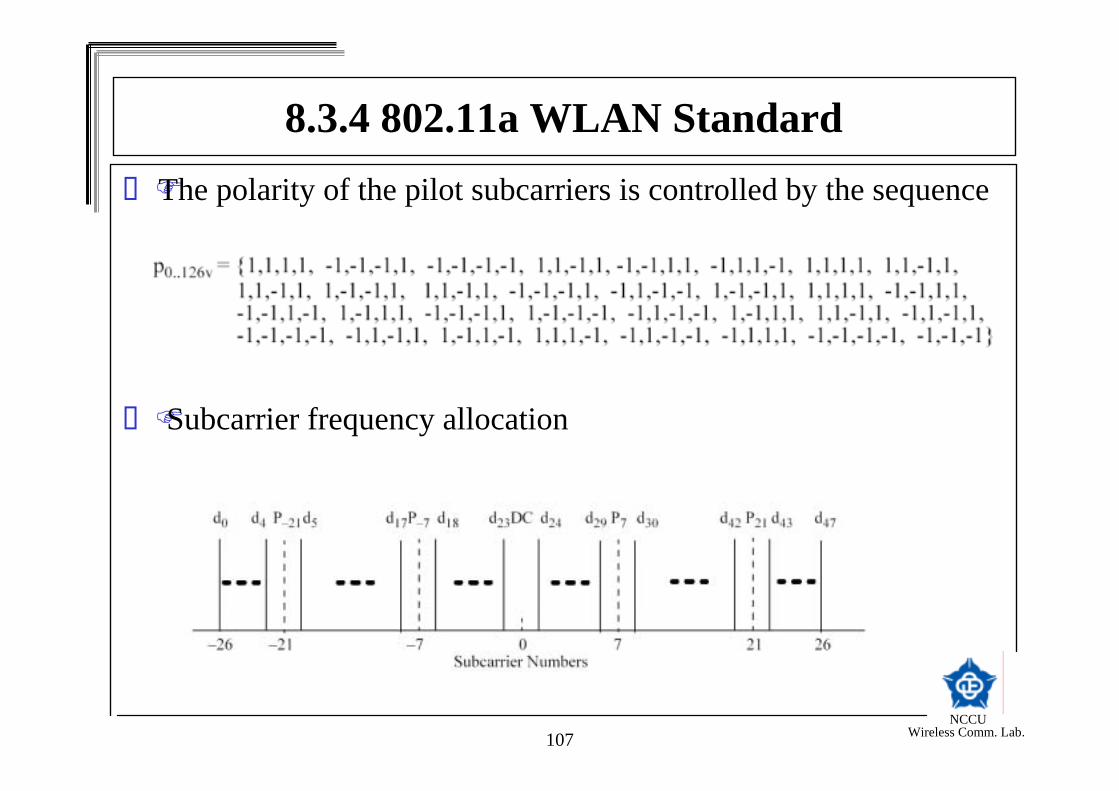
8.3.4 802.11a WLAN StandardThe polarity of the pilot subcarriers is controlled by the sequence
Subcarrier frequency allocation

NCCU Wireless Comm. Lab.108
8.3.4 802.11a WLAN Standard802.11a Transmitter and Receiver structure

NCCU Wireless Comm. Lab.109
8.4 IEEE 802.16 Broadband Wireless Access System
NCCU Wireless Comm. Lab.110
8.4.1 Introduction to IEEE 802.16BWAS is the broadband wireless technology used to deliver voice, data, Internet, and video service in the 25-GHz and higher spectrum.

NCCU Wireless Comm. Lab.111
BWAS Scenario
8.4.1 Introduction to IEEE 802.16

NCCU Wireless Comm. Lab.112
8.4.1 Introduction to IEEE 802.16IEEE 802.16 Wireless MAN Background
Target: FBWA (Fixed Broadband Wireless Access)Fast local connection to networkProject Development since 1998

NCCU Wireless Comm. Lab.113
8.4.1 Introduction to IEEE 802.16Point-to-Multipoint Wireless MAN: not a LAN
Base Station (BS) connected to public networksBS serves Subscriber Station (SSs)
SS typically serves a buildingProvide SS with access to public network.
Compared to Wireless LANMultimedia QoS not only contention-basedMany more usersMuch higher data ratesMuch longer distances
NCCU Wireless Comm. Lab.114
8.4.1 Introduction to IEEE 802.16Properties of 802.16
Broad BW: up to 134 Mbps in 28 MHz wide channel (10-66 GHz)Support simultaneous multiple services with full QoS
IPv4, IPv6, ATM, Ethernet, etc.BW on demand (per frame)MAC designed for efficient spectrum useComprehensive, modern and extensible securitySupport multiple frequency allocation from 2-66 GHz
OFDM & OFDMA for NLOS applications

NCCU Wireless Comm. Lab.115
8.4.1 Introduction to IEEE 802.16TDD & FDD
Link Adaptation: Adaptive modulation & codingPer subscriber, per burst, per up-/down- link
Point-to-multipoint topology, with mesh extensionsSupport for adaptive antennas and space-time codingExtensions to mobility

NCCU Wireless Comm. Lab.116
8.4.1 Introduction to IEEE 802.16802.16 Bit Rate and Channel Size
134.489.644.822.428
12080402025
9664321620
64-QAM bit rate(Mbps)
16-QAM bit rate(Mbps)
QPSK bit rate(Mbps)
Symbol Rate(Msym/s)
Channel Width(MHz)

NCCU Wireless Comm. Lab.117
8.4.1 Introduction to IEEE 802.16802.16 Link Adaptation Scenario

NCCU Wireless Comm. Lab.118
8.4.2 Introduction to Physical Layer of 802.16Physical Layer of 802.16
OFDM (WMAN-OFDM Air Interface): 256-FFT w/ TDMA (TDD/FDD)
OFDMA (WMAN-OFDMA Air Interface) : 2048-FFT w/ OFDMA (TDD/FDD)
Single-Carrier (WMAN-SCa Air Interface):TDMA (TDD/FDD)BPSK, QPSK, 4/16/64/256-QAM
NCCU Wireless Comm. Lab.119
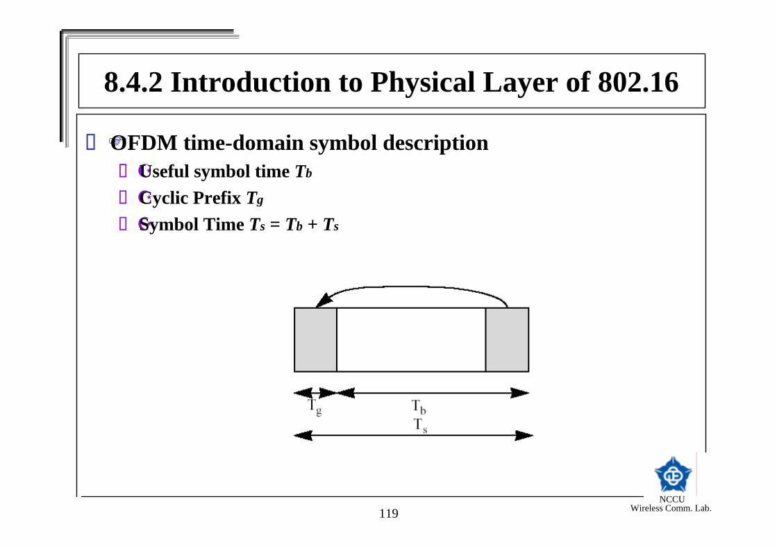
OFDM time-domain symbol descriptionUseful symbol time Tb
Cyclic Prefix Tg
Symbol Time Ts = Tb + Ts
8.4.2 Introduction to Physical Layer of 802.16
NCCU Wireless Comm. Lab.120
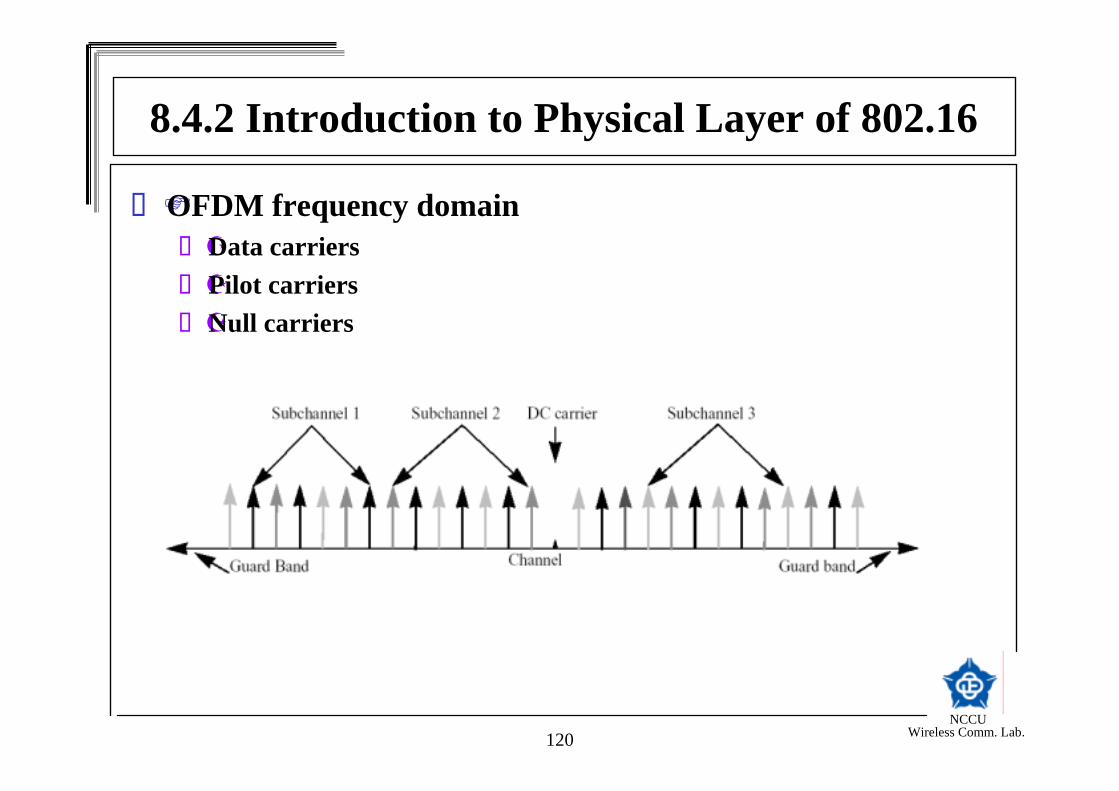
OFDM frequency domainData carriersPilot carriersNull carriers
8.4.2 Introduction to Physical Layer of 802.16

NCCU Wireless Comm. Lab.121
The Transmitted signal at the antenna
= ∑−=
−∆2/
2/
)(22Re)(used
used
gc
N
Nk
Ttfkjk
tfj ecets ππ
8.4.2 Introduction to Physical Layer of 802.16

NCCU Wireless Comm. Lab.122
Four types of forward error correction (FEC)Code Type 1: Reed-Solomon Code onlyCode Type 2: Reed-Solomon Code + Block convolutional codeCode Type 3: Reed-Solomon + Parity checkCode Type 4: Block Turbo code
8.4.2 Introduction to Physical Layer of 802.16

NCCU Wireless Comm. Lab.123
OFDM Carrier Allocations
8.4.2 Introduction to Physical Layer of 802.16

NCCU Wireless Comm. Lab.124
Transmit diversity – space time coding
8.4.2 Introduction to Physical Layer of 802.16
NCCU Wireless Comm. Lab.125
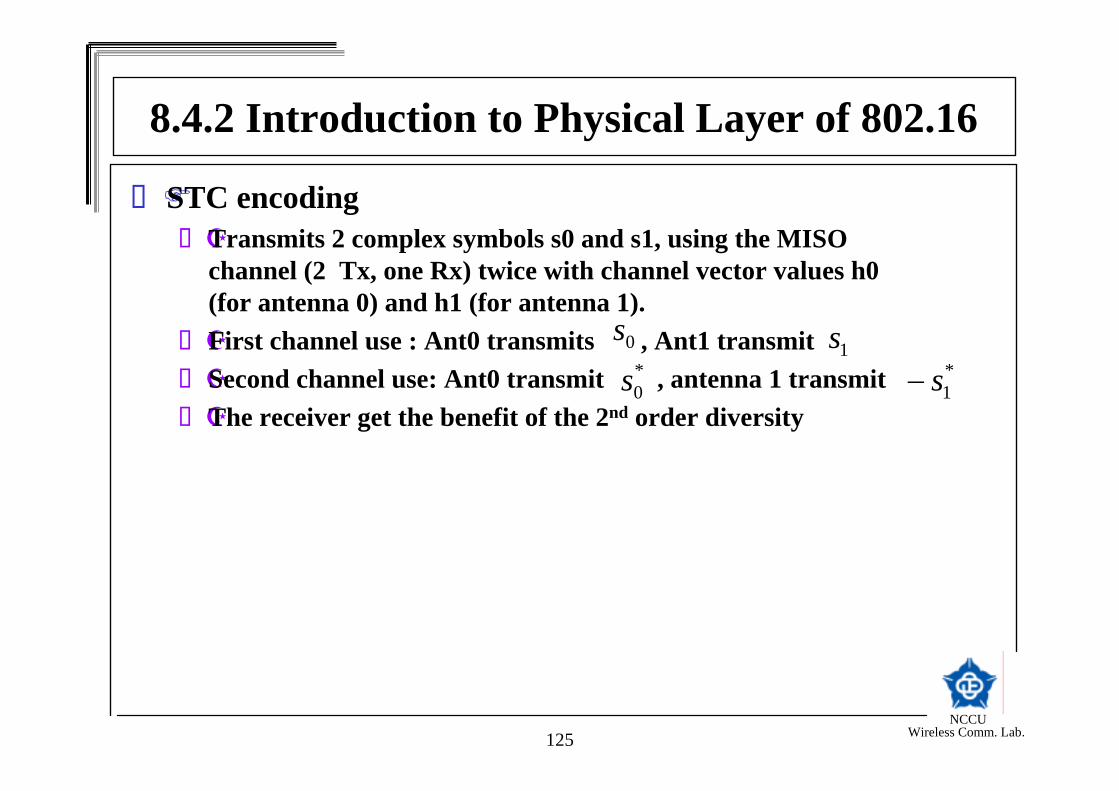
STC encodingTransmits 2 complex symbols s0 and s1, using the MISO channel (2 Tx, one Rx) twice with channel vector values h0 (for antenna 0) and h1 (for antenna 1).First channel use : Ant0 transmits , Ant1 transmit Second channel use: Ant0 transmit , antenna 1 transmit The receiver get the benefit of the 2nd order diversity
0s1s
*1s−
*0s
8.4.2 Introduction to Physical Layer of 802.16

NCCU Wireless Comm. Lab.126
STC Usage with OFDM
8.4.2 Introduction to Physical Layer of 802.16

NCCU Wireless Comm. Lab.127
Concatenated Reed-Solomon / convolutional code (RS-CC)
•RS code is derived from (255,239) RS code that can correct up to 8 symbol errors.
•The RS encoded block is then encoded by a convolutional code of rate ½ with generator polynomial
•Convolutional encoder
8.4.2 Introduction to Physical Layer of 802.16

NCCU Wireless Comm. Lab.128
8.4.2 Introduction to Physical Layer of 802.16Concatenated Reed-Solomon / convolutional code (RS-CC)
RS code is derived from (255,239) RS code that can correct up to 8 symbol errors.The RS encoded block is then encoded by a convolutional code of rate ½ with generator polynomial
Convolutional encoder

NCCU Wireless Comm. Lab.129
Puncturing Pattern
8.4.2 Introduction to Physical Layer of 802.16

NCCU Wireless Comm. Lab.130
Channel Coding and Modulation
8.4.2 Introduction to Physical Layer of 802.16

NCCU Wireless Comm. Lab.131
Block Turbo codesBased on the product of two component codes.Binary extended Hamming code or parity check code
8.4.2 Introduction to Physical Layer of 802.16

NCCU Wireless Comm. Lab.132
8.4.2 Introduction to Physical Layer of 802.16
The component codes are used in a two dimensional matrix form
kx information bits are encoded into nx bits by using (nx,kx)block code. After encoding the rows, the columns are encoded using a (ny,ky) block code, where the check bits of the first code are also encoded.
NCCU Wireless Comm. Lab.133
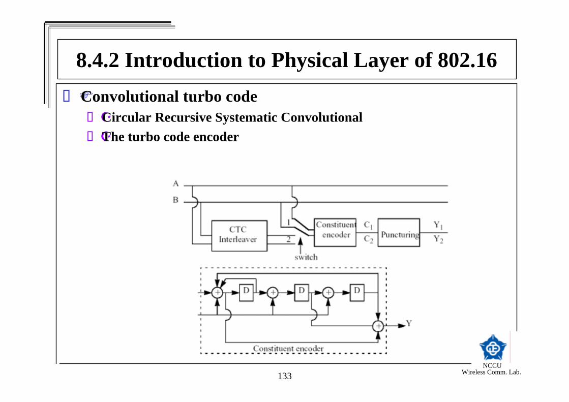
8.4.2 Introduction to Physical Layer of 802.16Convolutional turbo code
Circular Recursive Systematic ConvolutionalThe turbo code encoder
NCCU Wireless Comm. Lab.134
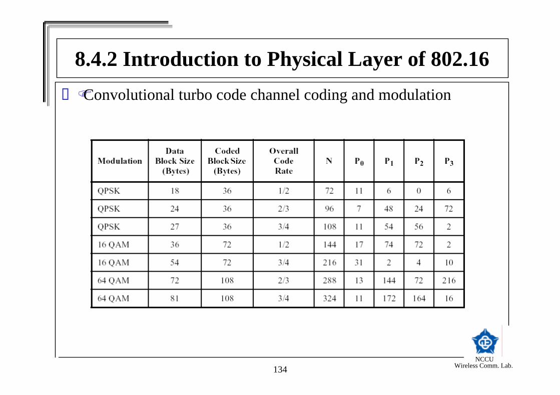
8.4.2 Introduction to Physical Layer of 802.16Convolutional turbo code channel coding and modulation


