Chapter 9 Transmission of chains Key points: ⑴ Failures; ⑵ Efficiency of polygon; ⑶ Lubrication methods, arrangement and tension of chain drives. Difficulties: Design procedure §9.1 Characteristics and Application of chain drives 1.Characteristics ⑴ big centre distance ⑵ smaller overall than belt drive ⑶ No elastic creep, positive Instantaneous ⑷ ⑸ smaller tension required and small force acting on the shafts ⑹ can operate under adverse working conditions such as high temperature, high humidity and oil pollution and so on. ⑺ operate only among parallel shafts ⑻ Has more noisy, more impact than belt drives ⑼ wearing lead to faulty engagement between 1
Transcript
Chapter 9 Transmission of chains
Key points: ⑴ Failures;
⑵ Efficiency of polygon;
⑶ Lubrication methods, arrangement and tension of chain
drives.
Difficulties: Design procedure
§9.1 Characteristics and Application of chain drives
1. Characteristics
⑴ big centre distance
⑵ smaller overall than belt drive
⑶ No elastic creep,
positive Instantaneous
⑷
⑸ smaller tension required and small force acting on the shafts
⑹ can operate under adverse working conditions such as high
temperature, high humidity and oil pollution and so on.
⑺ operate only among parallel shafts
⑻ Has more noisy, more impact than belt drives
⑼ wearing lead to faulty engagement between chain and sprockets
⑽ can not be used in big variable load and sudden reverse rotation
⑾ cost is higher than V-belt drives, because complicated manufacturing
and service such as lubricating and adjusting.
2. Application
Low-speed because wearing, impact, noise. As a rule, ,
1
High quality chain with small pitch, large number of teeth and effective
lubrication,
High-torque (P<100KW (<5000Kw)),
belt drive (P<20~30KW (<1000Kw)),
gear drive (P<60000KW )
,
§9.2 Types of chain drives
1. Classify
⑴ by their purpose
① Lifting/load chains, be used mainly in materials handling machinery.
② Hauling/towing chains, used for conveying machinery.
③ Power transmission chain used for transmitting mechanical energy.
⑵ by their structure
① Roller chain
② Silent chain
2. Roller chains
⑴ Components
Pins, bushings, rollers, inner side plates, outer side plates
Bushing and inner side plate, Pin and outer side plate —— tight fit
Roller and bushing, bushiing and pin —— clearance fit
Single strand, double-strand, three-strand, … quadruple-strand pt
Multiple-strand chains have same components except longer pins.
⑵ Joints
Cotter pin for even number of links and large pitch
Alligator clip for even number and small pitch
Offset link for odd number of links
⑶ Chain number
2
05B、06B、08B、08A、10A、12A、16A、20A……
The digits indicate the pitch of the chain in sixteenth of an inch.
(in)
(mm)
Suffix A——A series, standard sizes
Suffix B——B series, smaller and lighter sizes
Designation:
Chain number—Number of strand × Number of links Standard number
Example: 08A—1×80 GB1243.1—83
Single strand
Multiple strand
3. Silent chain
⑴ Guide plate
3
Inner guide plate better guidance for high speed and heavy-duty,
Outside guide plate for width of sprocket less than 25~30mm
⑵ Joints
① Cylindrical pin type
② Bushing type
③ Roller type
§9.3 Moving characteristics of chain drives
Chain average velocity
Speed ratio in
n
z
z121
2
2
1
On small sprocket, chain advanced speed
v v Rx 1 1 1cos cos
4
chain perpendicular speed
v v Ry 1 1 1sin sin
Similarly, on big sprocket, chain advanced speed
v v Rx 2 2 2cos cos
21 1
2
R
R
cos
cos
Instantaneous speed ratio
Only when , that is , the change ranges of and equal,
and when , , then
conclusion:Chain drives cannot move smoothly.
Efficiency of polygon:
§9.4 Appended dynamic loads of chain drives
1. Caused by periodical variable chain speed
当 180
1z时
ω↑ , p ↑,Fd ↑
2. Caused by periodical variable angular velocity of the driven sprocket
z↓, ↓,Fd ↑
Conclusion:
5
The larger speed and the larger chain pitch, the larger dynamic load.
§9-5 Force analysis of chain drives
1. Effective peripheral force
2. Centrifugal force
3. Sagging force
where a——Center distance of chain drive, mm
——Mass per chain length, ㎏/m, See table 9-1
——acceleration of gravity, m/s2
——Hanging factor when hanging value
——sag degree
——angle of gradient,°
For perpendicular installation,
For horizontal installation,
4. Tight side force Ignoring dynamic loads
5. Loose side force
§9.6 Design of roller chain drives
1. Failures
⑴ Fatigue breakage of the link plates due to the repeated application of
the tension in the tight side of the chain
⑵ Pitting on bushings or rollers surface due to the impact of the rollers
as they engage the sprocket teeth.
6
⑶ Wear between pins and bushings
Wear in the joints leading to elongation of the chain and faulty
engagement with the sprockets.
⑷ Gluing/veneer failure between pins and bushings owing to poor
lubrication or high speed
⑸ Impact damage caused by overload
⑹ Static strength failure of the joint elements for heavy load and low-
speed chain drives v 0 6. m / s
⑺ Wear of the sprocket teeth
2. Rated power curves for single strand
Experiment conditions:
z1 19 ;
Lp 100 pitches;
Single strand chain mounted horizontally
Steady load
Normal working environment
Recommended lubrication way, see fig 9.12
Service life of 15 000 h;
Relative elongation of chain causing by chain wear .
Fig 9.11: Rated power curve for A series of roller chain horizontally
centered shafts
Fig 9.12: → lubrication ways
type Ⅰ Artificial regular lubrication
type Ⅱ Drop lubrication
type Ⅲ Oil-bath lubrication or splash lubrication
type Ⅳ pressure-spray lubrication
If lubrication is poor or is not applied in the recommended way, value
7
in the figure should be reduced:
⑴ When , and no lubrication, → 015 0. P
⑵ When , poor lubrication, → 0 3 0 6 0. ~ . P
⑶ When 15 7. v m / s , poor lubrication, → 015 0 3 0. ~ . P
⑷ When v 7 m / s,lubrication must be used。
4. Modified power
The real working conditions are different from experiment condition.
Where —— Working condition factor
—— factor for number of teeth of small sprocket when ,
see Table 9.3
When failure is fatigue of plates (left fatigue curve),
When failure is impact fatigue of roller or bushing
(left fatigue curve),
—— chain length factor when , see Fig. 9.13
—— multiple-strand factor when number of strands does
equal 1 , see Table 9.4
4. Design procedure
Given: Transmitted power P,
Rotational speed of sprockets n1, n2 or speed ratio i
⑴ Specify numbers of teeth of sprockets and speed ratio
① Specify number of teeth of small sprocket
, see table 9.5
For smaller sprocket at very low speed, z 1min = 7.
uniform wearing,(relatively prime odd number):17、19、21、23、25、38、
57、95、114
8
② Compute number of teeth of big sprocket
Select an integer
Generally,
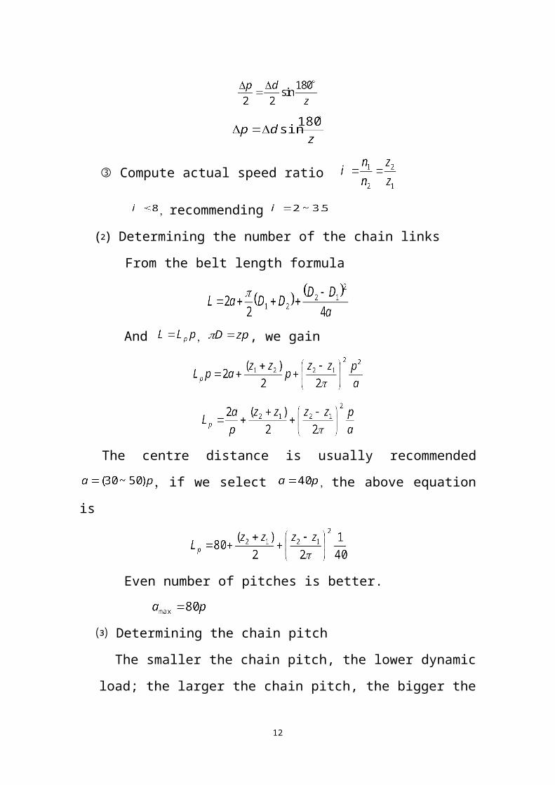
③ Compute actual speed ratio
, recommending
⑵ Determining the number of the
chain links
From the belt length
formula
And , , we gain
The centre distance is usually recommended ,if we select
,the above equation is
Even number of pitches is better.
⑶ Determining the chain pitch
9
The smaller the chain pitch, the lower dynamic load; the larger the
chain pitch, the bigger the power capacity.
Large pitch less-strand chain——low-speed heavy-duty,↑a↓i
Small pitch multiple-strand chain——High-speed heavy-duty, ↓a↑i
n1 P0 chain number, p
p, v recommended lubrication way
⑷ Computing chain length and center distance
① chain length
——the number of the chain links, the chain length in pitches
② Compute real center distance
Belt centre distance
Theoretical chain center distance:
In order to ensure a suitable sag: , actual center
distance is smaller than the theoretical.
The bigger value is for adjustable center distance.
⑸ Checking chain velocity
10
Fig 9-11
Fig 9-12
⑹ Force acting on the sprocket shaft
where
⑺ Static strength for low speed v 0 6. m / s
Where — calculate safety factor
—the limiting tension force for single strand, see Table 9.1
—number of strands
— Service factor, see table 9-9
§9.7 Roller chain sprockets
1. Basic parameters and principle sprocket sizes
⑴ p— chain pitch
d1—the maximum diameter of bushing
pt—the strand distance for multiple-strand
11
z—number of sprocket teeth
⑵ pitch diameter of a sprocket with z teeth for a chain with a pitch of p
is
Others can be seen in table 9-3, table 9-4
2. The shape of teeth three arcs-straight line 标注 3R GB1244-85
3. The structure of sprockets
4. Sprocket materials
Wear resistant, strength
Low carbon steel, medium carbon steel,
Low carbon alloy steel, medium carbon alloy steel,
Plain carbon steel,
Cast steel, gray iron
§9.8 Lubrication, arrangement and tensioning of chain drives
1. Lubrication methods
type Ⅰ Artificial regular lubrication
type Ⅱ Drop lubrication
5~20 drops/miniter Drop lubricator
type Ⅲ Oil-bath lubrication or splash lubrication
oil-disc
type Ⅳ pressure-spray lubrication
oil-pump, oil pipe
Lubricants:
L-AN32 20#
L-AN46 30#
L-AN60 40#
12
2. Arrangement
3. Tension of chain drives
Regularly adjusting by adjuster such as screw and eccentric
Automatically tensioning by springs or hangers
Supporting plates for long centre distance
Tension wheel: maybe sprocket or toothless roller with diameter closed