45
ille 2000 Software Engineering, 6th edition. Chapter 9 Slide 1 Chapter 9 Formal Specifications
| Date post: | 02-Jan-2016 |
| Category: |
Documents |
| Upload: | marcia-mcfarland |
| View: | 26 times |
| Download: | 0 times |

©Ian Sommerville 2000 Software Engineering, 6th edition. Chapter 9 Slide 1
Chapter 9
Formal Specifications

©Ian Sommerville 2000 Software Engineering, 6th edition. Chapter 9 Slide 2
Objectives
To explain why formal specification helps discover problems in system requirements.
To describe the use of: Algebraic specification techniques, and Model-based specification techniques
(including simple pre- and post-conditions).

©Ian Sommerville 2000 Software Engineering, 6th edition. Chapter 9 Slide 3
Formal methods
Formal specification is part of a more general collection of techniques known as “formal methods.”
All are based on the mathematical rep-resentations and analysis of requirements and software.
©Ian Sommerville 2000 Software Engineering, 6th edition. Chapter 9 Slide 4
Formal methods
Formal methods include: Formal specification Specification analysis and property proofs Transformational development Program verification (program correctness
proofs) Specifications are expressed with
precisely defined vocabulary, syntax, and semantics.

©Ian Sommerville 2000 Software Engineering, 6th edition. Chapter 9 Slide 5
Acceptance and use
Formal methods have not become main-stream as was once predicted, especially in the US. Some reasons why:1. Other, less costly software engineering
techniques (e.g., inspections / reviews) have been successful at increasing system quality. (Hence, the need for formal methods has been reduced.)
©Ian Sommerville 2000 Software Engineering, 6th edition. Chapter 9 Slide 6
Acceptance and use
2. Market changes have made time-to-market rather than quality the key issue for many systems. (Formal methods do not reduce time-to-market.)
3. The scope of formal methods is limited. They are not well-suited to specifying user interfaces. (Many interactive applications are “GUI-heavy” today.)
©Ian Sommerville 2000 Software Engineering, 6th edition. Chapter 9 Slide 7
Acceptance and use
4. Formal methods are hard to scale up to very large systems. (Although this is rarely necessary.)
5. The costs of introducing formal methods are high.
6. Thus, the risks of adopting formal methods on most projects outweigh the benefits.
©Ian Sommerville 2000 Software Engineering, 6th edition. Chapter 9 Slide 8
Acceptance and use
However, formal specification is an excellent way to find requirements errors and to express requirements unambig-uously.
Projects which use formal methods invariably report fewer errors in the delivered software.
©Ian Sommerville 2000 Software Engineering, 6th edition. Chapter 9 Slide 9
Acceptance and use
In systems where failure must be avoided, the use of formal methods is justified and likely to be cost-effective.
Thus, the use of formal methods is increasing in critical system development where safety, reliability, and security are important.

©Ian Sommerville 2000 Software Engineering, 6th edition. Chapter 9 Slide 10
Formal specification in the software process
Requirementsspecification
Formalspecification
Systemmodelling
Architecturaldesign
Requirementsdefinition
High-leveldesignelicitation
©Ian Sommerville 2000 Software Engineering, 6th edition. Chapter 9 Slide 11
Formal specification techniques
Algebraic approach – the system is specified in terms of its operations and their relationships via axioms.
Model-based approach (including simple pre- and post-conditions) – the system is specified in terms of a state model and operations are defined in terms of changes to system state.

©Ian Sommerville 2000 Software Engineering, 6th edition. Chapter 9 Slide 12
Formal specification languages

©Ian Sommerville 2000 Software Engineering, 6th edition. Chapter 9 Slide 13
Use of formal specification
Formal specification is a rigorous process and requires more effort in the early phases of software development.
This reduces requirements errors as ambiguities, incompleteness, and inconsistencies are discovered and resolved.
Hence, rework due to requirements problems is greatly reduced.

©Ian Sommerville 2000 Software Engineering, 6th edition. Chapter 9 Slide 14
Development costs with formal specification
Specification
Design andImplementation
Validation
Specification
Design andImplementation
Validation
Cost
Without formalspecification
With formalspecification
©Ian Sommerville 2000 Software Engineering, 6th edition. Chapter 9 Slide 15
Algebraic Specification of sub-system interfaces
Large systems are normally comprised of sub-systems with well-defined interfaces.
Specification of these interfaces allows for their independent development.
Interfaces are often defined as abstract data types or objects.
The algebraic approach is particularly well-suited to the specification of such interfaces.

©Ian Sommerville 2000 Software Engineering, 6th edition. Chapter 9 Slide 16
Sub-system interfaces
Sub-systemA
Sub-systemB
Interfaceobjects

©Ian Sommerville 2000 Software Engineering, 6th edition. Chapter 9 Slide 17
The structure of an algebraic specification
sort < name >imports < LIST OF SPECIFICATION NAMES >
Informal descr iption of the sor t and its operations
Operation signatures setting out the names and the types ofthe parameters to the operations defined over the sort
Axioms defining the operations over the sort
< SPECIFICATION NAME > (Gener ic Parameter)

©Ian Sommerville 2000 Software Engineering, 6th edition. Chapter 9 Slide 18
Specification components
Introduction – defines the sort (type name) and declares other specifications that are used
Description – informally describes the operations on the type
--------------------------------------------------------------------- Signature – defines the syntax of the
operations in the interface and their parameters Axioms – defines the operation semantics by
defining axioms which characterize behavior
©Ian Sommerville 2000 Software Engineering, 6th edition. Chapter 9 Slide 19
Types of operations
Constructor operations: operations which create / modify entities of the type
Inspection operations: operations which evaluate entities of the type being specified
Rule of thumb for defining axioms: define an axiom which sets out what is always true for each inspection operation over each constructor.
©Ian Sommerville 2000 Software Engineering, 6th edition. Chapter 9 Slide 20
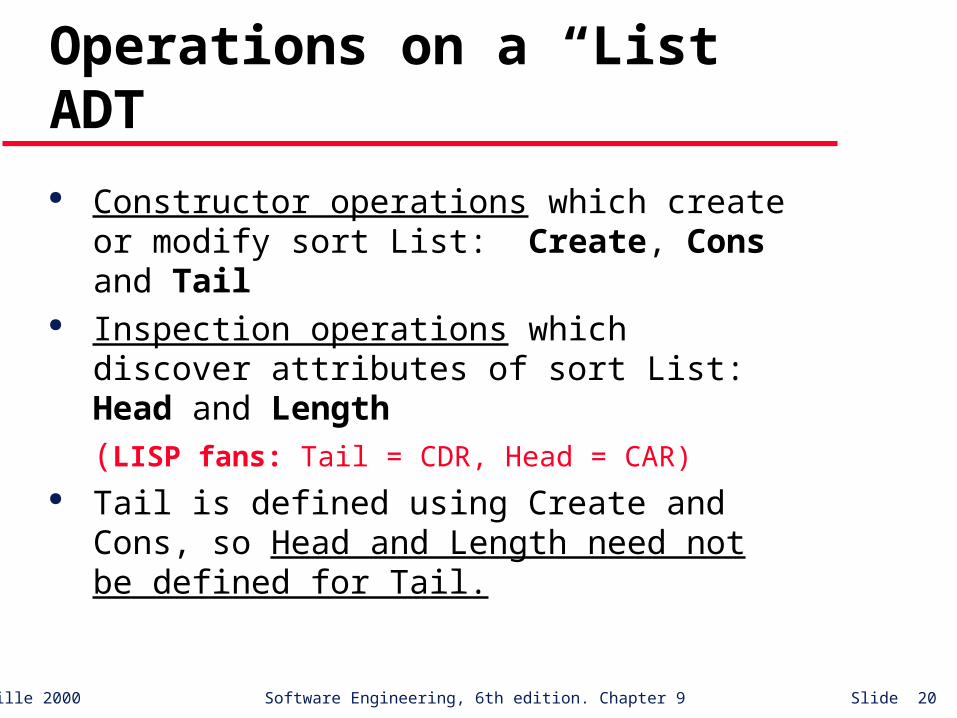
Operations on a “List” ADT
Constructor operations which create or modify sort List: Create, Cons and Tail
Inspection operations which discover attributes of sort List: Head and Length
(LISP fans: Tail = CDR, Head = CAR) Tail is defined using Create and Cons, so
Head and Length need not be defined for Tail.
©Ian Sommerville 2000 Software Engineering, 6th edition. Chapter 9 Slide 21
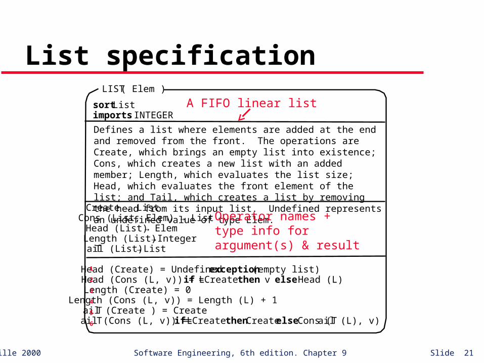
List specification
Head (Create) = Undefined exception (empty list)Head (Cons (L, v)) = if L =Create then v else Head (L)Length (Create) = 0Length (Cons (L, v)) = Length (L) + 1Tail (Create ) = CreateTail (Cons (L, v)) = if L =Create then Create else Cons (Tail (L), v)
sort Listimports INTEGER
Create → List Cons (List, Elem) → ListHead (List) → ElemLength (List) → IntegerTail (List) → List
LIST ( Elem )
Defines a list where elements are added at the end and removed from the front. The operations are Create, which brings an empty list into existence; Cons, which creates a new list with an added member; Length, which evaluates the list size; Head, which evaluates the front element of the list; and Tail, which creates a list by removing the head from its input list. Undefined represents an undefined value of type Elem.
A FIFO linear list
Operator names + type info for argument(s) & result
1
2
3
4
5
6

©Ian Sommerville 2000 Software Engineering, 6th edition. Chapter 9 Slide 22
Recursion in specifications
Tail (Cons (L, v)) = if L=Create then Create else Cons (Tail (L), v)
Tail (Cons ( [5, 7], 9)) = ?
= Cons (Tail ( [5, 7] ), 9) (axiom 6)
= Cons (Tail (Cons ([5], 7) ) , 9)
= Cons (Cons (Tail ([5]), 7) , 9) (axiom 6)
= Cons (Cons (Tail (Cons ([], 5) ), 7) , 9)
= Cons (Cons (Create, 7) , 9) (axiom 6)
= Cons ( [7], 9)
= [7, 9]

©Ian Sommerville 2000 Software Engineering, 6th edition. Chapter 9 Slide 23
Exercise
What does Head (Tail (L)) do?
L Head (Tail (L))
[ ] [a]
[a, b]
[a, b, c]
undefined
undefined
b
b
©Ian Sommerville 2000 Software Engineering, 6th edition. Chapter 9 Slide 24
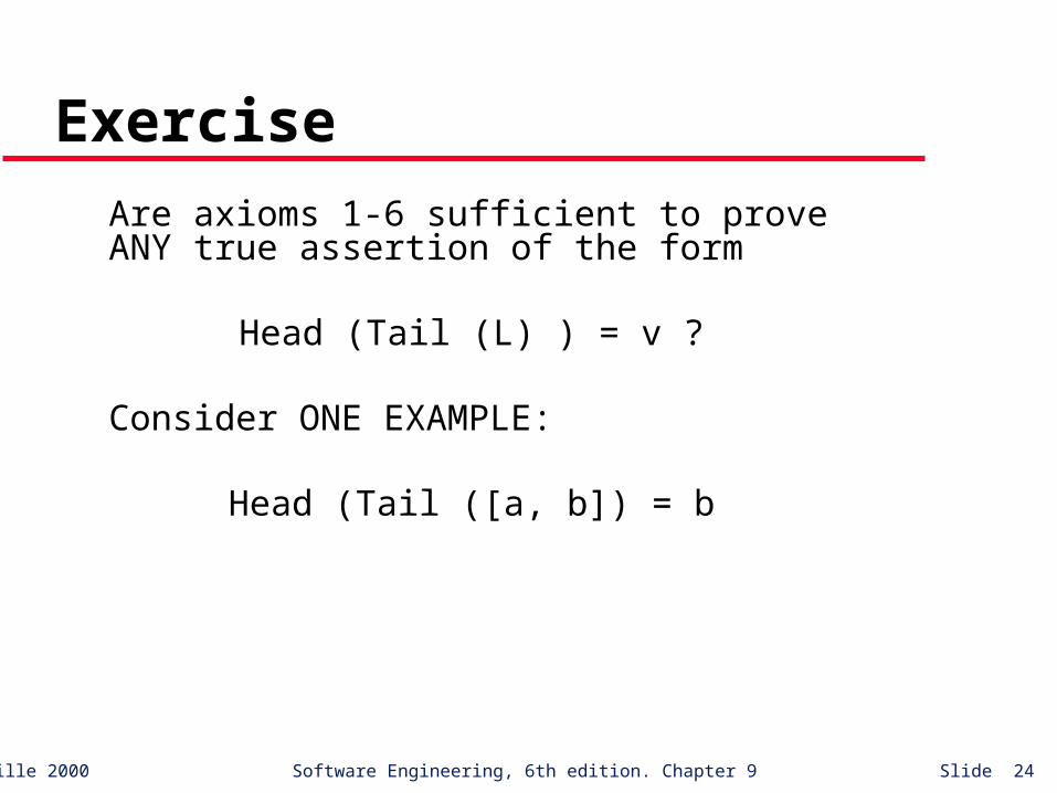
Exercise
Are axioms 1-6 sufficient to prove ANY true assertion of the form
Head (Tail (L) ) = v ?
Consider ONE EXAMPLE:
Head (Tail ([a, b]) = b

©Ian Sommerville 2000 Software Engineering, 6th edition. Chapter 9 Slide 25
Proof that Head (Tail ([a, b]) = b
Head (Tail ([a, b])) = Head (Tail (Cons ([a], b)))
= Head (Cons (Tail ([a]), b)) (axiom 6)
= Head (Cons (Tail (Cons ([ ], a)), b))
= Head (Cons ([ ], b)) (axiom 6)
= b (axiom 2)

©Ian Sommerville 2000 Software Engineering, 6th edition. Chapter 9 Slide 26
Exercise
So, we can prove Head (Tail ([a, b]) = b using the given axioms, but how could one show that the axioms are sufficient to prove ANY true assertion of the form
Head (Tail (L) ) = v ?
Moral: Showing correctness and completeness of algebraic specifications can be very tricky!
©Ian Sommerville 2000 Software Engineering, 6th edition. Chapter 9 Slide 27
Model-based specification
Algebraic specification can be cumber-some when object operations are not independent of object state (i.e., previous operations).
(System State) Model-based specification exposes the system state and defines operations in terms of changes to that state.
©Ian Sommerville 2000 Software Engineering, 6th edition. Chapter 9 Slide 28
Model-based specification
Z is a mature notation for model-based specification. It combines formal and informal descriptions and incorporates graphical highlighting.
The basic building blocks of Z-based specifications are schemas.
Schemas identify state variables and define constraints and operations in terms of those variables.

©Ian Sommerville 2000 Software Engineering, 6th edition. Chapter 9 Slide 29
The structure of a Z schema
contents Š capacity
Containercontents: capacity:
Schema name Schema signature Schema predicate
Natural numbers (0, 1, 2, …)
“invariants”, pre- & post- conditions
≤
Defines schema state
©Ian Sommerville 2000 Software Engineering, 6th edition. Chapter 9 Slide 30
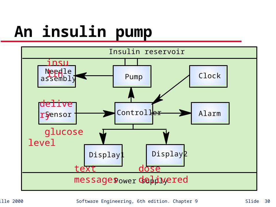
An insulin pump
Needleassembly
Sensor
Display1 Display2
Alarm
Pump Clock
Power supply
Insulin reservoir
Controller
insulin
delivery
glucose level
text messages dose delivered
©Ian Sommerville 2000 Software Engineering, 6th edition. Chapter 9 Slide 31
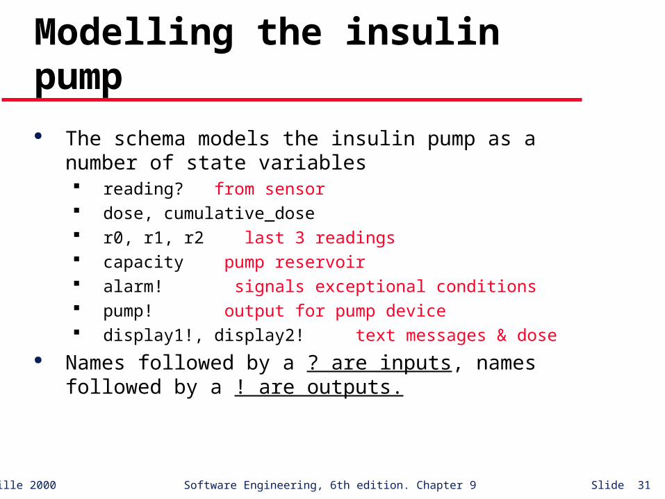
Modelling the insulin pump
The schema models the insulin pump as a number of state variables reading? from sensor dose, cumulative_dose r0, r1, r2 last 3 readings capacity pump reservoir alarm! signals exceptional conditions pump! output for pump device display1!, display2! text messages & dose
Names followed by a ? are inputs, names followed by a ! are outputs.

©Ian Sommerville 2000 Software Engineering, 6th edition. Chapter 9 Slide 32
Schema invariant
Each Z schema has an invariant part which defines conditions that are always true (schema predicates)
For the insulin pump schema, it is always true that: The dose must be less than or equal to the capacity of
the insulin reservoir. No single dose may be more than 5 units of insulin and
the total dose delivered in a time period must not exceed 50 units of insulin. This is a safety constraint.
display1! shows the status of the insulin reservoir.
©Ian Sommerville 2000 Software Engineering, 6th edition. Chapter 9 Slide 33
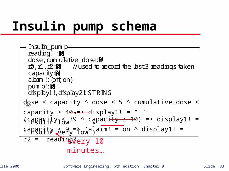
Insulin pump schema
Insulin_pumpreading? : dose, cumulative_dose: r0, r1, r2: // used to record the last 3 readings takencapacity: alarm!: {off, on}pump!: display1!, display2!: STRING
dose Š capacity dose Š 5 cumulative_dose Š 50capacity 40 display1! = " "capacity Š 39 capacity 10 display1! = "Insulin low"capacity Š 9 alarm! = on display1! = "Insulin very low"r2 = reading?
≤dose ≤ capacity ^ dose ≤ 5 ^ cumulative_dose ≤ 50capacity ≥ 40 => display1! = “ “(capacity ≤ 39 ^ capacity ≥ 10) => display1! = “Insulin low”capacity ≤ 9 => (alarm! = on ^ display1! = “Insulin very low”)r2 = reading?
every 10 minutes…
©Ian Sommerville 2000 Software Engineering, 6th edition. Chapter 9 Slide 34
The dosage computation
The insulin pump computes the amount of insulin required by comparing the current reading with two previous readings.
If these suggest that blood glucose is rising then insulin is delivered.
Information about the total dose delivered is maintained to allow the safety check invariant to be applied.
Note that this invariant always applies – there is no need to repeat it in the dosage computation.
©Ian Sommerville 2000 Software Engineering, 6th edition. Chapter 9 Slide 35
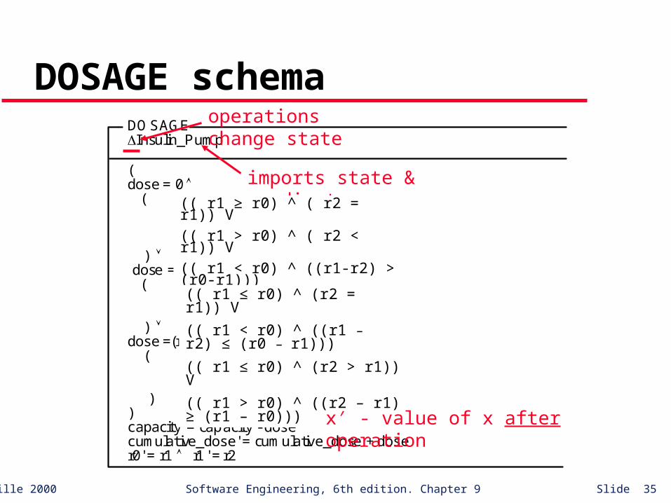
DOSAGE schemaDOSAGEInsulin_Pump
(dose = 0 (
r1 r0) ( r2 = r1)) (( r1 > r0) (r2 Š r1)) (( r1 < r0) ((r1-r2) > (r0-r1)))
) dose = 4 ( (( r1 Š r0) (r2=r1)) (( r1 < r0) ((r1-r2) Š (r0-r1))) ) dose =(r2 -r1) * 4 (
(( r1 Š r0) (r2 > r1)) (( r1 > r0) ((r2 - r1) (r1 - r0)))
))capacity' = capacity - dosecumulative_dose' = cumulative_dose + doser0' = r1 r1 ' = r2
operations change state
imports state & predicates(( r1 ≥ r0) ^ ( r2 = r1)) V
(( r1 > r0) ^ ( r2 < r1)) V
(( r1 < r0) ^ ((r1-r2) > (r0-r1)))
(( r1 ≤ r0) ^ (r2 = r1)) V
(( r1 < r0) ^ ((r1 – r2) ≤ (r0 – r1)))
(( r1 ≤ r0) ^ (r2 > r1)) V
(( r1 > r0) ^ ((r2 – r1) ≥ (r1 – r0)))
x′ - value of x after operation

©Ian Sommerville 2000 Software Engineering, 6th edition. Chapter 9 Slide 36
Output schemas
The output schemas model the system displays and the alarm that indicates some potentially dangerous condition.
The output displays show the dose computed and a warning message.
The alarm is activated if blood sugar is very low – this indicates that the user should eat something to increase his blood sugar level.

©Ian Sommerville 2000 Software Engineering, 6th edition. Chapter 9 Slide 37
Output schemasDISPLAYInsulin_Pump
display2!' = Nat_to_string (dose) (reading? < 3 display1!' = "Sugar low" reading? > 30 display1!' = "Sugar high" reading? 3 and reading? Š 30 display1!' = "OK")
ALARMInsulin_Pump
( reading? < 3 reading? > 30 ) alarm!' = on reading? 3 reading? Š 30 ) alarm!' = off
conversionNote conflict with “insulin low” msg.
^
≥ 3 ≤ 30
≥ ≤
^^

©Ian Sommerville 2000 Software Engineering, 6th edition. Chapter 9 Slide 38
Schema consistency
It is important that schemas be consistent. Inconsistency suggests a problem with system requirements.
The INSULIN_PUMP schema and the DISPLAY are inconsistent: display1! shows a warning message about the insulin
reservoir (INSULIN_PUMP) display1! Shows the state of the blood sugar (DISPLAY)
This must be resolved before implemen-tation of the system.

©Ian Sommerville 2000 Software Engineering, 6th edition. Chapter 9 Slide 39
Specification via Pre- and Post-Conditions
Predicates that (when considered together) reflect a program’s intended functional behavior are defined over its state variables.
Pre-condition: expresses constraints on program variables before program execution. An implementer may assume these will hold BEFORE program execution.
©Ian Sommerville 2000 Software Engineering, 6th edition. Chapter 9 Slide 40
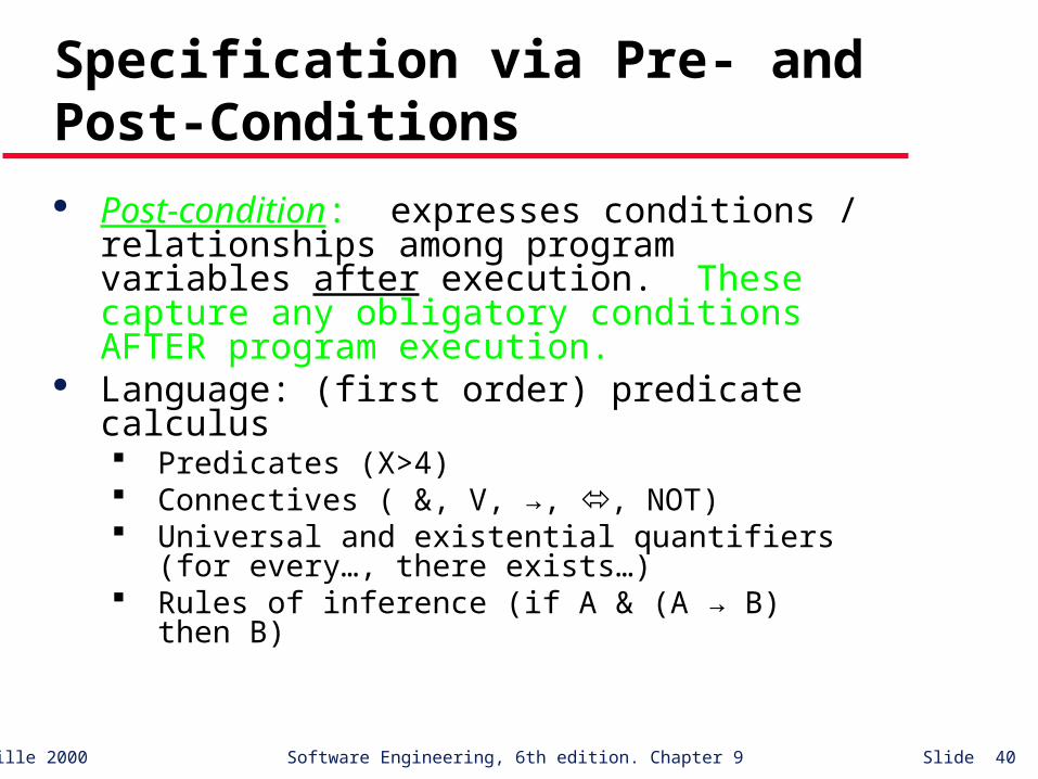
Specification via Pre- and Post-Conditions
Post-condition: expresses conditions / relationships among program variables after execution. These capture any obligatory conditions AFTER program execution.
Language: (first order) predicate calculus Predicates (X>4) Connectives ( &, V, →, , NOT) Universal and existential quantifiers (for
every…, there exists…) Rules of inference (if A & (A → B) then B)

©Ian Sommerville 2000 Software Engineering, 6th edition. Chapter 9 Slide 41
Example 1
Sort a non-empty array LIST[1..N] into increasing order.Pre-cond: N ≥ 1
Post-cond: For_Every i, 1 ≤ i ≤ N-1, LIST[i] ≤ LIST[i+1] & PERM(LIST,LIST’)
©Ian Sommerville 2000 Software Engineering, 6th edition. Chapter 9 Slide 42
Example 2
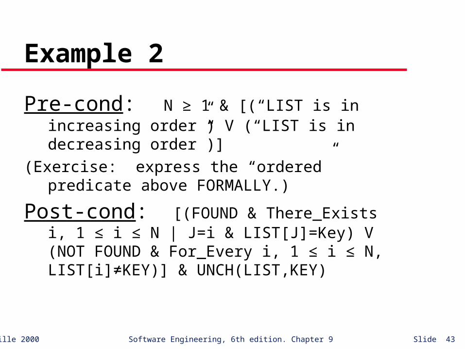
Search a non-empty, ordered array LIST[1..N] for the value stored in KEY. If present, set FOUND to true and J to an index of LIST which corresponds to KEY. Otherwise, set FOUND to false.
©Ian Sommerville 2000 Software Engineering, 6th edition. Chapter 9 Slide 43
Example 2
Pre-cond: N ≥ 1 & [(“LIST is in increasing order”) V (“LIST is in decreasing order”)]
(Exercise: express the “ordered” predicate above FORMALLY.)
Post-cond: [(FOUND & There_Exists i, 1 ≤ i ≤ N | J=i & LIST[J]=Key) V (NOT FOUND & For_Every i, 1 ≤ i ≤ N, LIST[i]≠KEY)] & UNCH(LIST,KEY)

©Ian Sommerville 2000 Software Engineering, 6th edition. Chapter 9 Slide 44
Key points
Formal system specification complements informal specification techniques.
Formal specifications are precise and unambiguous. They remove areas of doubt in a specification.
Formal specification forces an analysis of the system requirements at an early stage. Correcting errors at this stage is cheaper than modifying a delivered system.

©Ian Sommerville 2000 Software Engineering, 6th edition. Chapter 9 Slide 45
Key points
Formal specification techniques are most applicable in the development of critical systems.
Algebraic techniques are particularly suited to specifying interfaces of objects and abstract data types.
In model-based specification, operations are defined in terms of changes to system state.


