Chapter Contents JPRs addressed in this chapter Vessel Markings, Arrangement, Construction, and Systems Chapter 4 Common Vessel Markings ................. 101 Bulbous Bow 101 Compartment Division 102 Bow/Stern Thruster 102 Draft Marks 102 Load Line (Plimsoll Mark/Line) 103 Arrangement of Vessel Spaces............ 104 General (Typical) 104 Tankage 107 Vessel Compartment Access and Egress................................. 109 Watertight/Weathertight Doors 109 Interior Joiner Doors 111 Hatches/Hatchways 111 Superstructures 112 Machinery Spaces 112 Cargo Spaces 113 Vessel Construction ......................... 114 Framing Systems 115 Bulkheads 116 Decks, Platforms, and Levels 118 Construction Materials 119 Large Vessel Systems ...................... 121 Power Generation and Lighting 122 Heating, Refrigeration, Air-Conditioning, and Ventilation Systems 122 Fuel and Ballast Transfer Systems 123 Mooring Systems 124 Steering Systems 124 Propulsion Systems and Thrusters 124 Communication Systems 127 Cargo-Handling Systems ................... 130 Break Bulk 131 Roll-On/Roll-Off (RO/RO) 131 Containerized and Intermodal 131 Liquid Bulk 132 Dry Bulk 134 Smaller Vessel Systems.................... 134 Commercial Vessels 135 Recreational Vessels 136 Chapter Review .............................. 136 Key Terms ..................................... 137 Skill Sheets ................................... 139 This chapter provides information that addresses the following job performance requirements (JPRs) of NFPA 1005, Standard for Professional Qualifications for Marine Fire Fighting for Land-Based Firefighters, 2019 Edition. 4.1.1 4.1.2 4.2.1 4.2.2 4.4.1 4.4.2 4.4.3 4.4.4
Transcript
Chapter Contents
JPRs addressed in this chapter
Vessel Markings, Arrangement, Construction, and Systems Chapter 4
This chapter provides information that addresses the following job performance requirements (JPRs) of NFPA 1005, Standard for Professional Qualifications for Marine Fire Fighting for Land-Based Firefighters, 2019 Edition.
4.1.14.1.2
4.2.14.2.2
4.4.14.4.2
4.4.34.4.4
Learning Objectives
100 Chapter 4 • Vessel Markings, Arrangement, Construction, and Systems
1. Describe common vessel markings. [4.1.1, 4.1.2, 4.2.1]
2. List the major structural compartments found on most vessels. [4.1.1, 4.1.2, 4.2.1]
3. Describe vessel compartment access and egress. [4.1.1, 4.1.2, 4.2.1]
4. Explain considerations for vessel construction. [4.1.1, 4.1.2, 4.2.1]
5. List the major systems necessary on a large vessel. [4.1.1, 4.1.2, 4.2.1, 4.4.1, 4.4.2, 4.4.4]
8. Skill Sheet 4-1: Operate communications equipment at a marine incident. [4.2.2, 4.4.1, 4.4.2, 4.4.3]
Chapter 4 • Vessel Markings, Arrangement, Construction, and Systems 101
Chapter 4
Vessel Markings, Arrangement, Construction,
and Systems
A significant portion of firefighter training programs is devoted to properties of land-based construction materials, building construction, and building systems (including ventilation, fire detection systems, and fire-suppression systems). An understanding of similar features as they apply to vessels can greatly reduce the risk to land-based firefighters during fire suppression activities. This chapter describes the following elements:
• Common vessel markings• Arrangement of vessel spaces• Vessel compartment access and egress• Vessel construction
• Large vessel systems • Cargo-handling systems • Smaller vessel systems
Common Vessel MarkingsVessels typically display hull markings that identify specific features of the vessel’s construction that may be of use to emergency personnel (see the Arrangement section for information on structural components). Many items on deck are marked to identify their purpose. Items include hatches, piping, tank covers, vents, and other equipment.
The hull is the main structural body of a vessel. Markings on a ves-sel’s hull identify specific design features such as a bulbous bow or a bow or stern thruster, and specific locations such as compartment divi-sions. Hull markings also indicate the vessel’s maximum safe draft or depth (Figure 4.1).
Bulbous BowMany vessels are equipped with bul-bous bows. The presence of a bulbous bow is normally indicated on the hull with markings on either side of the bow, above the waterline, and in the vicinity of the anchor. These markings provide a warning that the vessel’s bow protrudes forward below the waterline of a loaded vessel.
Figure 4.1 Hull markings on merchant vessels indicate the ship’s draft, the presence of a bulbous bow and/or bow thruster, and compartment divisions. Photo: Courtesy of Douglas Dillon.
102 Chapter 4 • Vessel Markings, Arrangement, Construction, and Systems
Observation of the bulbous bow marking is important and must be available to the Incident Commander (IC) at an emergency response. The bulbous bow may be visible at the beginning of response operations, but not hours later when conditions have changed. A new crew may be operating a small boat in the area and may not be aware of the bulbous bow or the significance of the symbol.
Compartment DivisionVessels often have special markings along the hull of the vessel. These marks often identify where a bulkhead divides two spaces. In addition, they may also indicate the frame number and/or an abbreviated space name (for example, ER for engine room). Compartment division markings are useful in identifying areas within the hull.
Bow/Stern ThrusterThruster marks can be found at the bow and stern of a vessel and are provided to warn other vessels that might be affected by the thrust being generated. A vessel may be equipped with a single thruster or multiple thrusters in one location.
Draft MarksDraft marks are located at the bow (forward), amidships (middle), and stern (aft) of a vessel on both the port and starboard sides. Draft marks may be in units of feet and inches (English units) or in meters and decimeters (metric units). Draft marks in English units are placed on the hull at 1-foot intervals above the lowest part of the vessel’s hull. The standard practice is to use numerals that are 6 inches high and located so that the bottom of the numeral is at the 1-foot interval. Water at the bow just touching the bottom of numeral 16, for example, indicates that the draft forward is 16 feet 0 inches. Water just covering the top of numeral 16 would indicate a draft of 16 feet 6 inches. With practice, an observer can easily estimate draft to the nearest 3 inches, and with experience an observer can estimate to the nearest inch (Figure 4.2).
Figure 4.2 If the English system is used, draft markings are six inches high and six inches apart. The bottom of each number shows the foot draft mark.
Table 4.1Metric Draft Marks
7 m
6 m
1 m
eter
706866646260
7 m6.8 m6.6 m6.4 m6.2 m
6 m
DecimetersMeters/Decimeters Read As
Chapter 4 • Vessel Markings, Arrangement, Construction, and Systems 103
While a vessel may have a numeral 16 on its hull, it is not unusual to find only single digits between 10-foot intervals. The numerals above 10 are usually 1 through 9, followed by 20, followed by 1 through 9, followed by 30. If water is at the bottom of a numeral 5, look at the numbers above the 5 to determine if the draft is 5 feet (1.5 m), 15 feet (4.5 m), 25 feet (7.5 m), or 35 feet (10.5 m). Drafts of 25 feet to 40 feet (7.5 m to 12 m) in ballast are typical. Very large tankers may have drafts over 65 feet (19.5 m).
Draft marks in metric units are based on the meter, which is 3.28 feet (about 10 percent longer than a yard), and the decimeter (a tenth of a meter). Metric drafts are marked at every meter by a number, sometimes followed by the letter M. Intermediate drafts are placed every 20 decimeters (0.2 m/8 in). Numerals are 10 decimeters (0.1 m/4 in) high. A variation of metric draft marks uses decimeters only. The 1-meter draft mark is shown as 10 decime-ters. A draft mark of 66 decimeters indicates a draft of 6.6 meters. The draft mark numerals are still 10 decimeters (0.1 m) high and set 20 decimeters (0.2 m) apart (Table 4.1).
Load Line (Plimsoll Mark/Line)Draft marks provide important information about the stress acting on a vessel’s hull. Vessels of 24 meters or more include a symbol near the midship section of both port and starboard hulls. This symbol is known as the load line or the Plimsoll mark/line. The load line indicates the maximum draft to which a vessel can be submerged for rea-sons of stability or hull strength in various parts of the world and in different seasons. The load line mark indicates the maximum draft for various seasons and seas (Figure 4.3, p. 104).
The horizontal line through the circle/disk is at the same level as the “Summer Load Line” and indicates whether or not the ship’s cargo is evenly distributed. The two letters on either side of the circle represent the Classification Society under which the vessel is registered; for example, AB stands for the American Bureau of Shipping. Timber load line marks, which allow ships to carry extra timber as cargo, are seen on cargo vessels in the Great Lakes and other lumber-producing regions.
A full list of Classification Societies and their abbreviations is available on the IACS website. For additional information on vessel draft, see the section on Monitoring a Vessel in Chapter 5, Vessel Hazards and Safety.
CAUTION: A submerged load line mark requires the chief officer or master to evaluate the impact on stability and strength of the hull .
Superstructure
Hull
Vessel Hull and Superstructure
FTF
TSWWNA
AB – American Bureau of Shipping
TF – Tropical Freshwater load line
F – Freshwater load line
T – Tropical saltwater load line
S – Summer saltwater load line
W – Winter saltwater load line
WNA – Winter North Atlantic load line
A B
2019
1817
16
2019
181716
A B
Load Line (Plimsoll) Marks
104 Chapter 4 • Vessel Markings, Arrangement, Construction, and Systems
Arrangement of Vessel SpacesLarge vessels are unique structures combining the features of a warehouse and material-handling fa-cility with those of a hotel and an industrial power plant. These functions must be kept separate from one another for functional and safety reasons, and they must be protected from the sea. The following sections describe the arrangement of these functions. They also describe typical locations of doors and hatches, the means of operating these closures, and safety precautions that must be observed.
General (Typical) A vessel is composed of two major structural components: the hull and the superstructure (Figure 4.4). The hull refers to the structure enclosing the full length of the vessel and extend-ing vertically from the keel (bottom beam) to the uppermost continuous deck. Within the hull, com-partments are provided for machinery, cargo, and tankage. In some vessels, crew living spaces may also be contained within the hull.
Superstructure refers to the structure placed on top of the hull that extends from port to starboard. The term deckhouse is sometimes used to refer to Figure 4.4 The hull is the watertight body of a vessel. The
superstructure is located above the main deck.
Figure 4.3 The Plimsoll line indicates the maximum depth to which a vessel can be safely immersed when loaded with cargo. This depth varies with the time of year and water density, as well as the ship’s dimensions and type of cargo.
Chapter 4 • Vessel Markings, Arrangement, Construction, and Systems 105
the superstructure, but there is a difference between a superstructure and a deckhouse. A deckhouse is smaller (usually one to two stories) and does not extend to the sides of the vessel. Fire reported in a superstructure, like a multistory building, could become a major incident. Fire reported in a deckhouse, like a garage, is likely to be far less serious, depending on what is being stored.
The superstructure generally houses the vessel control spaces and living spaces for the crew; it may also contain shops, laboratory facilities, aircraft facilities, offices, and some specialized cargo spaces. The superstructure is generally located at one of three positions along the hull: house forward, house amidships, or house aft.
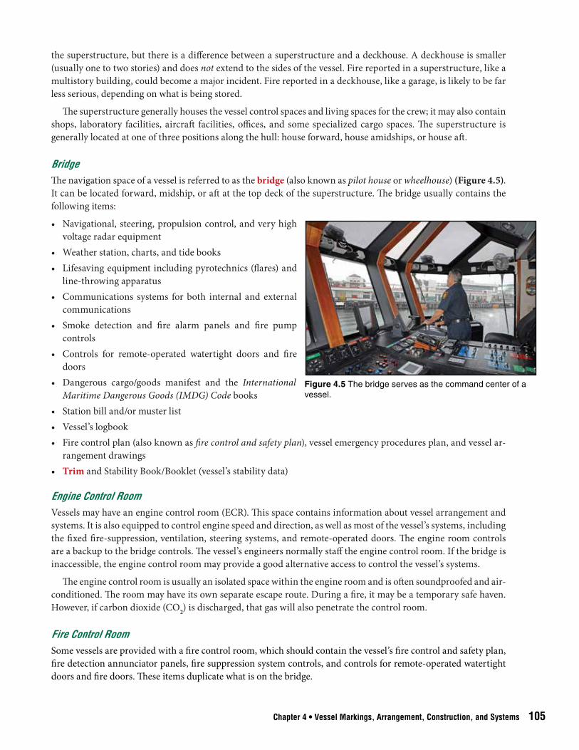
BridgeThe navigation space of a vessel is referred to as the bridge (also known as pilot house or wheelhouse) (Figure 4.5). It can be located forward, midship, or aft at the top deck of the superstructure. The bridge usually contains the following items:
• Navigational, steering, propulsion control, and very high voltage radar equipment
• Weather station, charts, and tide books• Lifesaving equipment including pyrotechnics (flares) and
line-throwing apparatus• Communications systems for both internal and external
communications• Smoke detection and fire alarm panels and fire pump
controls• Controls for remote-operated watertight doors and fire
doors• Dangerous cargo/goods manifest and the International
Maritime Dangerous Goods (IMDG) Code books • Station bill and/or muster list• Vessel’s logbook• Fire control plan (also known as fire control and safety plan), vessel emergency procedures plan, and vessel ar-
rangement drawings• Trim and Stability Book/Booklet (vessel’s stability data)
Engine Control RoomVessels may have an engine control room (ECR). This space contains information about vessel arrangement and systems. It is also equipped to control engine speed and direction, as well as most of the vessel’s systems, including the fixed fire-suppression, ventilation, steering systems, and remote-operated doors. The engine room controls are a backup to the bridge controls. The vessel’s engineers normally staff the engine control room. If the bridge is inaccessible, the engine control room may provide a good alternative access to control the vessel’s systems.
The engine control room is usually an isolated space within the engine room and is often soundproofed and air-conditioned. The room may have its own separate escape route. During a fire, it may be a temporary safe haven. However, if carbon dioxide (CO2) is discharged, that gas will also penetrate the control room.
Fire Control RoomSome vessels are provided with a fire control room, which should contain the vessel’s fire control and safety plan, fire detection annunciator panels, fire suppression system controls, and controls for remote-operated watertight doors and fire doors. These items duplicate what is on the bridge.
Figure 4.5 The bridge serves as the command center of a vessel.
106 Chapter 4 • Vessel Markings, Arrangement, Construction, and Systems
Fire and Foam Room This space houses the pumps and tanks that distribute fire fighting foam throughout the vessel. The room will often have spare foam storage, emergency muster turnout gear, and equipment. It may also be an emergency team muster point.
Accommodation SpacesCrew living (accommodation) spaces include berthing (sleeping) areas, washrooms, a galley, food storerooms, recreation spaces, and a laundry facility. If the vessel is primarily a cargo vessel, living spaces are usually con-tained within the superstructure. In a military or a passenger vessel, living spaces are found throughout the superstructure and the hull. Small vessels such as supply boats and fishing vessels also have living spaces in both the superstructure and hull.
Storage SpacesStorage spaces, likely to contain hazardous substances, are located on many types of vessels. During emergency response, they should be treated as confined spaces. Storage spaces include the following areas:
• Chemical sample lockers on board chemical tankers• Paint lockers• Battery rooms• Oxygen and acetylene bottle storage rooms• Engine room chemical storage• Carbon dioxide (CO2) storage rooms • Trash compactor spaces• Sanitary waste treatment and sewage holding tank rooms• Steering gear rooms (typically used for storage of machinery space lubricants and boiler chemicals)
Cargo SpacesCargo spaces are spread along the length of the hull to evenly distribute the weight of the cargo. Placing cargo within the hull lowers the vessel’s center of gravity, which contributes to its stability. These spaces contain a wide variety of cargos, potentially including hazardous materials. Cargo spaces usually extend from the main deck to the bottom or double-bottom.
CAUTION: Assume every cargo space contains a hazardous atmosphere .
Machinery SpacesMachinery spaces contain the equipment that pro-pels the vessel, generates electricity, and provides heating and cooling (Figure 4.6). The machin-ery space also contains fire pumps and controls for various shipwide systems. The main machin-ery space (engine room) contains smoke and fire alarm panels, controls for remote-activated water-tight doors and bilge pumps (small pumps in the lowest inner part of hull), fire pumps, and controls for the power distribution and ventilation systems. The engine room is typically located below the ves-sel’s funnel (also called smokestack or stack). Some
Figure 4.6 Vessel machinery spaces may contain fire pumps and alarm system controls.
Fuel Fuel
Fuel Fuel
Ballast Water Ballast Water
Ballast WaterBallast Water
Cargo Hold Cargo Hold
Cargo HoldCargo Hold
Cargo
Tank
Cargo
Tank
Bow Thruster
Machinery
Storage
Storage
Engine Room
Lazarette
PumpRoom
TrimTank
Machinery Arrangement
Outboard Profile
Chapter 4 • Vessel Markings, Arrangement, Construction, and Systems 107
offshore supply vessels are exceptions to this rule and have machinery spaces aft, but their funnels are located well forward of the main machinery space to provide a clear deck area aft (Figure 4.7).
Shop spaces are often found near machinery spaces. Shop spaces may contain flammable liquids, pressure vessels, and flammable gas cylinders for cutting, welding, and brazing operations. Small machinery spaces con-taining specialized equipment may be located throughout the vessel. A space containing steering machinery is found at the aft (toward the rear) end of the vessel. A small space containing an emergency generator can usually be found on an upper deck of the vessel’s superstructure, near the vessel’s stack. Examples of specialized machin-ery spaces include:
• Pump rooms (handle liquid cargo)• Refrigeration spaces (contain compressors and anhydrous ammonia or other refrigerants for refrigerated cargo
spaces)• Fan rooms (contain equipment to move air throughout the vessel)
EnginesThe engines of a commercial vessel may be located amidships (toward the middle of the vessel), but are more likely to be located aft. This arrangement leaves the widest part of the vessel available for cargo space and reduces the length of the shaft required between the engine and propeller. Military combat vessels have high-powered engines and are more likely to have their engines located amidships due to the size of the power plant. Types of vessel en-gines and propulsion systems are addressed in greater detail later in this chapter (see the Systems sections).
TankageTanks are located throughout a vessel to contain liquid cargo, ballast, and the vessel’s fuel and oil, drinking and waste water, and other liquids. Tanks located along the bottom of a vessel usually contain fuel and water from vessel operations. Tanks that extend up the vessel’s sides and contain ballast or fuel oil are called wing tanks (Figure 4.8, p. 108).
Figure 4.7 The engine room at the stern of this offshore supply vessel provides maximum space for cargo storage and clears the aft deck for cargo handling. Courtesy of Howard Chatterton.
Aft Peak Tank(Water Ballast Tank)
Engine Room
Deck Tanks
Pump Room
Forward Peak Tank(Water Ballast Tank)
Inboard Profile
Vessel's Fuel TanksDouble Bottom Tanks
Deep Tank
Cargo Tanks
Starboard
Typical Tank Arrangement
Port
Front View
Double Bottom
Wing Tanks Wing Tanks
108 Chapter 4 • Vessel Markings, Arrangement, Construction, and Systems
The lowest deck of a vessel is usually a few feet (meters) above the vessel’s bottom. This lowest deck protects against vessel loss in the case of damage to the vessel’s bottom. The top of a series of adjacent tanks along the bottom of the hull forms a surface called the double bottom (also known as inner bottom) and those tanks are called double-bottom tanks.
Some tanks are dedicated to carrying ballast water, which is weight used to improve vessel stability (see the sec-tion on Fuel and Ballast Transfer Systems). Tanks holding sink water, shower water, laundry water, or dishwashing water are called gray water tanks. Tanks holding sewage, oily water, or any other liquid that must be treated before being released to the environment are called black water tanks. Both gray and black water tank contents must be disposed of in a controlled manner (using oily water separators and sewage treatment systems) to avoid pollution of the environment.
Figure 4.8 Wing tanks extend up the side of a tanker vessel and are often used for cargo. Fuel is stored in the double-bottom tanks that run along the bottom of the hull.
Chapter 4 • Vessel Markings, Arrangement, Construction, and Systems 109
Tanks serve an important function in managing the trim, the list, and the stability of a vessel (see Chapter 5, Vessel Hazards and Safety, for more information on trim). Peak tanks are located at both ends of the vessel, the extreme forward (fore peak tank) and aft (aft peak tank). Water can be pumped to and from these tanks to control trim. Tanks designated as clean ballast tanks are reserved for seawater and are filled to maintain stability when the vessel is traveling with a light cargo load.
Fuel is often stored in double-bottom tanks and deep tanks. They are usually located in the center of the vessel and may extend vertically through one or more decks. Fuel is usually pumped from a double-bottom tank to a deep tank (settling tank) to allow any water in the fuel to settle to the bottom.
Fuel from the upper sections of the deep tank is supplied to a day tank or service tank. These tanks are usually located in the engine room, or share a common bulkhead with the engine room. Fuel is gravity-fed from the day or service tank to supply the vessel’s engines. The gravity-fed process eliminates the need to continuously run a pump to operate a piece of machinery. Originally, a vessel’s crew pumped enough fuel into the tank to last a day’s worth of operations, but today it may be considerably more. Day or service tanks can hold several thousand gal-lons (liters) of fuel and are exposures in the event of an engine room fire.
Maritime regulations require that a separation space be provided between certain holds and tanks. Flammable cargo tanks cannot share a common bulkhead with the machinery space. Oil tanks and water tanks cannot share a common bulkhead. A separation space is provided by a small empty space or tank called a cofferdam or void. The space is usually built to the minimum dimensions required by the regulations. Any cofferdam or void must be considered a confined space with a possible hazardous atmosphere.
Vessel Compartment Access and EgressAccess to or egress from spaces aboard a vessel is made through doors located in bulkheads and hatches that are located on decks. Doors and hatches may be manually or power operated, and some may be remotely controlled. Vessel doors and hatches are very heavy compared to the doors and roof hatches on shoreside structures. The following sections describe the types and construction of doors and hatches, the procedures for operating them safely, and the access/egress situations of various vessel spaces.
Watertight/Weathertight DoorsWatertight and weathertight doors are located at doorways leading from the weather decks into the hull and superstructure. Watertight doors are also located in the hull at doorways in watertight bulkheads. Both water-tight and weathertight door openings are raised above deck level and have a raised frame called a coaming. A coaming provides some protection against water on the deck flowing into a compartment when the door is open. Watertight doors provide a higher degree of flooding protection than weathertight doors. Firefighters staying low and following the deck edge in search of a door can move right past one if they do not remember to reach up past the coaming height to locate the door.
CAUTION: Coamings present serious tripping hazards when a person is moving around in low visibility .
Watertight and weathertight doors are equipped with dogs (levers) that wedge the door tight against a rubber gasket to form a waterproof seal. Dogs are operable from either side of the door, and pushing the handle upward usually opens the dogs (Figure 4.9 a-c, p. 110).
Watertight doors may be indicated by class on a vessel’s fire control plan, so it is important to know the mean-ing of the class numbers. The three classes of watertight doors are described as follows:
• Class 1 — Hinged door• Class 2 — Sliding door, operated by hand gear only• Class 3 — Sliding door, operated by power and hand gear
110 Chapter 4 • Vessel Markings, Arrangement, Construction, and Systems
Door-Operating Mechanisms
Some Class 1 watertight doors are fitted with individual dogs and may require operating as many as eight dogs to open or secure them. Considerable force may be required to oper-ate the dogs. A short section of pipe called a dogging wrench (similar to a cheater bar) is usually mounted on brackets beside the door. This pipe section can be slipped over the end of a dog to provide leverage.
To open hinge-side dogs, start with the top, then open the bottom, and finally open the mid-dle one (Figure 4.10). Door hinges are slotted to allow some door movement against the gas-ket. This movement may give some indication of pressure, smoke, or flashover or backdraft conditions behind the door in a fire situation. A Class 1 door with individually operated dogs serves spaces that are not entered very often. The door may be fully opened using the same sequence (top, bottom, and middle dogs) on the opposite side of the hinge
Spaces that must be entered often are fitted with quick-acting watertight doors. These are still Class 1 doors (because they are hinged), but one wheel or lever operates all of the dogs at once. Due to small passageway size, it is often difficult to open a Class 1 watertight door without standing in the path of the door’s swing or in the middle of the door opening.
Failure to follow precautions with Class 1 doors can result in a person suddenly being exposed to
Figure 4.10 To open a watertight door, open the dog(s) nearest the hinge(s) first and follow the order shown above. This sequence keeps the closure from springing and makes it easier to operate the remaining dogs.
Figure 4.9 a-c a) When closed, this doorway is made watertight by the coaming at the bottom and the levers (dogs) that create a watertight seal. b) The dogging wrench slips over the handle of a dog to provide additional leverage. c) One wheel can operate all of the dogs at once.
Chapter 4 • Vessel Markings, Arrangement, Construction, and Systems 111
smoke or flashover conditions, being pulled into the initial negative pressure of a backdraft, or being flattened by a steel door violently forced open by internal pressure. The Class 1 door itself weighs 300 to 350 pounds (150 kg to 175 kg). A 2 psi (14 kPa) {0.14 bar} overpressure will force a standard 26-x 66-inch (650 mm by 1 650 mm) watertight door to swing under a force of 3,400 pounds (1 540 kg).
CAUTION: In an emergency situation, the dogs should be operated slowly and not allowed to completely clear the edge of the door until firefighters check for pressure or backdraft conditions behind the door . If normal conditions are indicated, the dogs can be fully turned to allow the door to open .
Class 2 doors (sliding watertight doors operated by hand gear only) may be found in old commercial vessels in a bulkhead between two watertight spaces. Sliding watertight doors found in most modern commercial vessels will be Class 3 doors (sliding watertight doors operated by power and hand gear). Class 3 doors in commercial vessels are most often found in the bulkhead between the main engine room and an auxiliary machinery space or the shaft alley. The doors are installed to provide easy access through a watertight bulkhead.
The status of all remote-operated doors must be determined in an emergency. These doors provide a possible means of attacking an engine room fire from a position low in the vessel. However, since these doors can be closed remotely, they pose the risk of cutting off escape routes, trapping firefighters, and severing fire hoses. Class 3 doors are equipped with a local manual control. When these doors are used for access in a fire situation, a firefighter must be stationed at this control to protect fire attack teams from unexpected door closures.
CAUTION: The automatic/remote closure should be locked out/tagged out when emergency responders are staged and advancing through these areas .
Interior Joiner DoorsDoors leading from interior passageways to compartments within a vessel are called joiner doors. These doors are equipped with lever- or doorknob-operated latches similar to those found in a hotel. The doors have at least the same fire ratings as the bulkheads in which they are placed (see Bulkheads section). Door construction is often steel or aluminum with an interior core of insulation material.
Under fire conditions, a vessel’s structure may expand and deform, causing doors to jam. At sea, a vessel’s mo-tion, a collision, or running aground may also cause the structure to distort and doors to jam. For these reasons, accommodation-space doors may be fitted with kick-out panels to allow emergency escape.
Hatches/HatchwaysHatches or hatchways are openings providing access through decks. These openings can be too small for a firefighter wear-ing self-contained breathing apparatus (SCBA) to enter and exit (Figure 4.11).
Hatch covers are located on coamings and present a trip-ping hazard with the added potential for a much longer fall. Watertight hatch covers are secured by the same dog mecha-nisms as Class 1 watertight doors. A wheel operates the dogs on most quick-acting watertight hatch covers. The direction to turn to open the door, usually counterclockwise, is often indi-cated on the wheel.
CAUTION: If an emergency responder wearing protective equipment cannot fit through a small hatch or hatchway, the responder may need to remove the SCBA backpack assembly (not the facepiece) to enter . The responder should only remove the backpack assembly if specifically trained to do so .
Figure 4.11 As demonstrated in this training exercise, hatches or hatchways between decks may be too small for a firefighter wearing SCBA to enter or exit.
112 Chapter 4 • Vessel Markings, Arrangement, Construction, and Systems
Some hatches may be installed flush with the deck. A large T-shaped key is usually hung on the adjacent bulk-head. This key can be inserted into a slot and turned to release and open the hatch. Various mechanisms are used to hold a hatch open, including latches, chains, and support arms.
Large hatch covers with individually operated dogs are often fitted with smaller scuttles. These scuttles are generally about 18 inches (450 mm) in diameter and allow quick crew access without having to release all of the dogs on the main cover.
Cargo hatch covers secure the large openings over cargo holds. These watertight hatches are either power-operated or require cranes to remove and replace the covers. Power-operated hatches require the vessel’s power for operation. Cargo hatches are substantial structures. The hatch covers (and associated coamings and stiffeners) on a container vessel can be as much as 2 feet (0.6 m) thick and weigh as much as a loaded container (30 to 40 tons [27 T to 36 T]). However, it may be possible to force these hatches open, or make a hole in them, with power tools.
Firefighters should also be aware of a type of container vessel that operates with open holds; that is, without hatch covers. These vessels rely on pumps in the cargo holds to remove any water that may enter between the hatch coaming and the stacks of containers.
Hatch Cover Safety
Even small hatch covers are surprisingly heavy. When open, they are usually held in the open position by a spring-loaded latch. NEVER place hands or fingers on a coaming when passing through a hatch-way. Hands or fingers are likely to be crushed or amputated if the hatch cover should fall.
• Counterweights on self-closing doors and hatch covers exposed to fire may fail and fall.
• Once opened, hatch covers must be secured in the open position. Changes in vessel trim and list (tilt) could cause unsecured hatch covers to move.
SuperstructuresAccess to and egress from the superstructure is usually made through doors located on open decks at each superstructure level (Figure 4.12). These doors may provide excellent access points for fire attack. Interior levels of the superstructure are connected by ladders (stairs) and may have either open (without covers) or closed hatchways. Open stairways (also called companionways) provide vertical paths for products of combustion and fire extension during fire situations. Some superstructures may be equipped with elevators that present the same paths for products of combustion and the same res-cue problems found in shoreside structures.
CAUTION: Security measures that may limit superstructure access include simple door locks, padlocks, or more complicated locking devices . It may not be possible to force exterior doors open with standard fire department forcible entry tools . If possible, the vessel’s crew should unlock all exterior doors before entering an interior fire room .
Machinery SpacesThe engine room or main machinery space is required to have at least two exits, but compartments within the engine room might only have one exit. On many vessels, the hatch at the top of a secondary escape ladder may be locked from the in-side for security reasons. If firefighters get to the top of the
Figure 4.12 Doors located on open decks at each superstructure level can serve as access points for fire attack. Courtesy of Captain John Taylor.
Muffler
Engine Room Access/Egress Routes
Stack Access
EscapeTrunk
Shaft Alley Diesel Engine
NormalAccess
Chapter 4 • Vessel Markings, Arrangement, Construction, and Systems 113
ladder in a fire situation and find the hatch padlocked, the key for the padlock should be on a hook nearby. The location of the key should be identified before entering a vessel with an engine room fire.
WARNING: Obstacles to access and egress should be identified and resolved before entering the engine room . The engine room will have two means of access and egress . However, spaces within the engine room, such as lockers, storage rooms, and fuel rooms, may not have two means of egress or access .
Normal access to and egress from machinery spaces is usually through doors and hatches located within the superstructure. Additional access/egress may be found through a door in the side of the stack or by way of a hatch on the main deck. The hatch provides access to an escape trunk, a steel shaft with a vertical ladder leading from the lowest level of the machinery space to the main deck (Figure 4.13).
A watertight door protects the emergency escape trunk at the bottom level. Firefighters attempting to gain ac-cess to the machinery spaces using the escape trunk may find several obstacles, such as the deck hatch secured from the inside or the door at the bottom of the escape trunk barred. In these situations, entry to machinery spaces through escape trunks may not be possible.
The shafting between the engine(s) and propeller(s) is located in a watertight space known as the shaft alley. On some vessels, the shaft alley may provide an emergency access to or escape path from the engine room. Emergency access to the engine room could be made through a main deck hatch with a vertical ladder to the shaft alley and then through a watertight door to the machinery space.
The machinery spaces on some vessels are equipped with skylights. Machinery spaces may also be equipped with hatches to allow removal and installation of equipment. Skylights and hatches are means of getting access to the engine room for entry, for the introduction of fire-suppression agents, or for ventilation.
Cargo SpacesCargo space access/egress is usually made through small hatches located between the main hatch covers. Some vessels have port to starboard passageways and athwartships (side-to-side) passageways on the second deck (deck below the main deck) with doors that provide access to the holds. Entry to and egress from the cargo space is usu-ally made by a vertical ladder. The ladder is often poorly maintained and may be damaged from the movement of the cargo.
Figure 4.13 Doors and hatches in the superstructure provide required access to and egress from the engine room.
Deck is in Tension
Hogging Sagging
Hull is in Tension
Deck is inCompression
Hull is inCompression
114 Chapter 4 • Vessel Markings, Arrangement, Construction, and Systems
Emergency responders must treat cargo spaces like confined spaces, regardless of their size. Before entering cargo spaces, have a marine chemist, fire department hazardous materials or confined-space rescue team, or other qualified person certify that a safe atmosphere is present.
WARNING: Use extreme caution when entering any cargo space . Many seemingly harmless products, such as fruit or wood chips, can deplete the oxygen level and produce carbon monoxide in cargo spaces . Even inserting one’s head into an ullage hole (opening for measuring liquids) can be deadly .
Vessel ConstructionThe structure of a vessel, like that of a building, must support its own weight, the weight of objects placed in and on it, and the loads imposed by both wind and precipitation (rain, snow, or ice). In addition, the vessel structure must sustain the pressure of water on its sides and bottom, loads created by moving through waves, and loads cre-ated by its rolling and pitching motion (dynamic loads). A vessel is designed to hold a specific type and amount of cargo and is shaped to move easily through the water.
Stresses on Vessels
If a vessel is held by its ends and pushed inward, the vessel is said to be in compression or under com-pressive stress. If the ends are pulled apart, the vessel will be in tension or under tensile stress. If the ends are twisted in opposite directions, the vessel will be in torsion, also known as torsional or racking stress. Vessels at sea or those loading or unloading cargo in port are subjected to these same stresses.
If a box is supported at its ends and weights are placed in the box, the box bends and becomes lower in the center than at the ends. The metal top of the box is under compression and the bottom of the box is under tension, which creates a condition known as sag. If a box is supported only in the center, the ends droop. The metal top is under tension and the bottom is under compression, creating a condition known as hog (Figure 4.14).
The underwater shape and the buoyant support of a vessel change along its length. At sea, waves change the distribution of buoyancy, and the vessel’s hull experiences regularly changing conditions of sagging and hogging. Placement of weight in the vessel, such as fuel, cargo, or fire fighting water, can also cause the hull to sag or hog.
A vessel is constructed using various materials arranged into structural components that are sized to resist the forces it may experience. These structural components include frames, bulkheads, decks, platforms, and levels. Knowledge of the arrangement of these components can assist firefighters in locating themselves within the vessel, gaining access to compartments, and predicting fire behavior and spread.
Figure 4.14 A ship’s hull curves upward in the middle when it hogs and downward in the middle when it sags.
Closely SpacedTransverse
Frames
Widely SpacedLongitudinal
Frames
KeelShellPlating
Transverse
Bulkhead
Systems Framing
Transverse
Bulkhead
Chapter 4 • Vessel Markings, Arrangement, Construction, and Systems 115
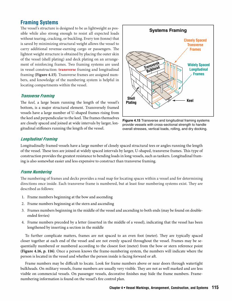
Framing SystemsThe vessel’s structure is designed to be as lightweight as pos-sible while also strong enough to resist all expected loads without tearing, cracking, or buckling. Every ton (tonne) that is saved by minimizing structural weight allows the vessel to carry additional revenue-earning cargo or passengers. The lightest weight structure is obtained by placing the outer skin of the vessel (shell plating) and deck plating on an arrange-ment of reinforcing frames. Two framing systems are used in vessel construction: transverse framing and longitudinal framing (Figure 4.15). Transverse frames are assigned num-bers, and knowledge of the numbering system is helpful in locating compartments within the vessel.
Transverse FramingThe keel, a large beam running the length of the vessel’s bottom, is a major structural element. Transversely framed vessels have a large number of U-shaped frames rising from the keel and perpendicular to the keel. The frames themselves are closely spaced and joined at wide intervals by larger, lon-gitudinal stiffeners running the length of the vessel.
Longitudinal FramingLongitudinally framed vessels have a large number of closely spaced structural tees or angles running the length of the vessel. These tees are joined at widely spaced intervals by larger, U-shaped, transverse frames. This type of construction provides the greatest resistance to bending loads in long vessels, such as tankers. Longitudinal fram-ing is also somewhat easier and less expensive to construct than transverse framing.
Frame NumberingThe numbering of frames and decks provides a road map for locating spaces within a vessel and for determining directions once inside. Each transverse frame is numbered, but at least four numbering systems exist. They are described as follows:
1. Frame numbers beginning at the bow and ascending
2. Frame numbers beginning at the stern and ascending
3. Frames numbers beginning in the middle of the vessel and ascending to both ends (may be found on double-ended ferries)
4. Frame numbers preceded by a letter (inserted in the middle of a vessel), indicating that the vessel has been lengthened by inserting a section in the middle
To further complicate matters, frames are not spaced to an even foot (meter). They are typically spaced closer together at each end of the vessel and are not evenly spaced throughout the vessel. Frames may be se-quentially numbered or numbered according to the closest foot (meter) from the bow or stern reference point (Figure 4.16, p. 116). Once a person knows the frame-numbering system, the numbers will indicate where the person is located in the vessel and whether the person inside is facing forward or aft.
Frame numbers may be difficult to locate. Look for frame numbers above or near doors through watertight bulkheads. On military vessels, frame numbers are usually very visible. They are not as well marked and are less visible on commercial vessels. On passenger vessels, decorative finishes may hide the frame numbers. Frame-numbering information is found on the vessel’s fire control plan.
Figure 4.15 Transverse and longitudinal framing systems provide vessels with cross-sectional strength to handle overall stresses, vertical loads, rolling, and dry docking.
Main Deck
Frame-Numbering Systems
KeelFrame Numbers AP FP33 28 23 18 13 8 3 0
Forward to Aft
AP FP3 8 13 18 23 28 330
Aft to Forward
AP FP36 31 23 18 13 8 3 0
Forward to Aft with New Section Inserted
M4M5 M3 M1
M2
116 Chapter 4 • Vessel Markings, Arrangement, Construction, and Systems
CAUTION: Land-based firefighters need to maintain an awareness of where they are within a vessel and the location of their exits at all times .
Bulkheads Vessels are divided into vertical sections by bulkheads (walls) (Figure 4.17). Bulkheads are usually located at a frame. They may carry the number of the frame or be numbered sequentially from the bow or the stern. Bulkheads are positioned to perform the following functions:
• Provide strength to the hull.• Separate cargo spaces from each other and from machinery spaces.• Provide protection against collision, flooding, or fire.
The collision bulkhead must be watertight from the bottom of the ship, up to the bulkhead deck. The collision bulkhead cannot have doors, manholes, ventilation ducts, or other openings fitted in the bulkhead below the bulkhead deck. Steps or recesses are allowed, and a single pipeline can penetrate the bulkhead for filling and emp-tying the forepeak tank. This bulkhead provides protection against flooding should the vessel ram directly into another vessel or fixed object. Knowledge of watertight subdivision bulkheads and fire zones can aid in confining a fire, gaining access for suppression, and dealing with water runoff.
Watertight Subdivision BulkheadsWatertight bulkheads provide protection against flooding. Main transverse watertight bulkheads divide the hull into two or more watertight subdivisions. The space in the hull between two main transverse watertight
Figure 4.16 Numerical values given to transverse frames can provide a needed point of reference for firefighters aboard a vessel.
Aft
Forward
Shell Plating
Shell Plating
Compartment Bulkheads
LongitudinalBulkhead
TransverseBulkhead
Chapter 4 • Vessel Markings, Arrangement, Construction, and Systems 117
bulkheads is a main watertight subdivision. In most cargo vessels, bulkheads are spaced so that any one main watertight subdivision can be flooded without causing the vessel to sink. Such vessels are called one-compartment subdivision vessels.
Any damage involving a watertight bulkhead may flood two subdivisions and result in loss of the vessel if the flooding is not controlled. In small vessels, such as tugboats and fishing vessels, the engines are often so large that bulkheads cannot be placed close enough together to protect against sinking. These vessels are called zero-compartment subdivision vessels.
Passenger vessels must withstand flooding of at least two subdivisions. Naval vessels are expected to receive damage and are designed to survive flooding of two or three major watertight subdivisions.
Watertight bulkheads extend from the keel to a deck well above the vessel’s waterline. In a deep-draft vessel, going over a watertight bulkhead and back down to the desired deck level can be a long climb, such as passage from a lower deck aft of a watertight
bulkhead to the same deck just forward of the bulkhead. In order to allow the vessel’s crew access between ma-chinery spaces that are separated by watertight bulkheads, remote-closing watertight doors are sometimes placed in those bulkheads. These doors pose the following hazards for firefighters in a fire situation:
• Flooding or fire fighting water can enter two (or more) subdivisions if doors are left open.• Closing doors automatically or by a remote operator can possibly trap firefighters.• Doors may not close tightly because of fire hoses in the doorway (allowing flooding to occur), or (more likely)
as doors close they may sever fire hose.
Fire Zone SubdivisionsWatertight bulkheads and fire-rated bulkheads divide a vessel into vertical fire zones. As mentioned earlier, doors in fire-rated bulkheads are required to have the same fire rating as the bulkhead. The International Convention for the Safety of Life at Sea (SOLAS) defines the fire-resistance rating (Classes A, B, and C) of bulkheads on com-mercial vessels.
The Class A bulkhead is made of steel. It prevents passage of smoke and flames for a period of 1 hour when subjected to the standard fire test. In addition, Class A bulkheads may be insulated so that:
1. A bulkhead classified A-60 prevents the temperature on the unexposed side of the bulkhead from rising more than 250°F (120°C) in 1 hour.
2. A bulkhead classified A-30 prevents the temperature on the unexposed side of the bulkhead from rising more than 250°F (120°C) in 30 minutes.
Sometimes a Class A-60 door will be fitted into a Class A or Class A-30 bulkhead because most doors are made to Class A-60 standards. It is not cost effective to settle lesser ratings.
CAUTION: Due to the effectiveness of bulkhead insulation, it may be possible to walk by a compartment on fire without detecting heat .
A Class B bulkhead is made of approved incombustible material(s). It prevents passage of flame for 30 minutes when subjected to the standard fire test. A B-15 bulkhead is insulated to prevent the temperature on its unexposed
Figure 4.17 Load-bearing and nonload-bearing bulkheads create vertical separations in a vessel, much like walls in a building. They also provide structural strength and protection.
Flying Bridge Deck
Boat Deck
Main Deck
Bridge Deck
Double Bottom
Upper Deck
Second DeckThird Deck
0-4 Level
Deck-Labeling Examples
Military Vessel
Passenger Vessel
0-2 Level
Main Deck (1)
0-3 Level
Inner Bottom (4)
0-1 Level
Second Deck (2)Third Deck (3)
118 Chapter 4 • Vessel Markings, Arrangement, Construction, and Systems
side from rising more than 250°F (120°C) in 15 minutes. An intact Class C bulkhead is also made of incombustible material(s). It is not required to meet requirements for flame passage or temperature rise. However, it will stop smoke spread, will not stop heat spread, and may have a combustible veneer.
Standard Fire Test
In a standard fire test, specimens of bulkheads or decks are exposed to high temperatures for an ex-tended period of time. The temperatures correspond to standard time-temperature. The U.S. Code of Federal Regulations (Title 46 CFR 190.07-5, Construction and Arrangement; Definitions) and the Canada Shipping Act, both of which implement the International Maritime Organization (IMO) require-ment for fire testing, require the following sequences of time and temperature:
• 5 minutes — 1,000°F (538°C)
• 10 minutes — 1,300°F (704°C)
• 30 minutes — 1,550°F (843°C)
• 60 minutes — 1,700°F (927°C)
Decks, Platforms, and LevelsDecks, platforms, and levels divide the vessel horizontally. The main deck is the highest deck that is continuous from bow to stern. A platform or flat divides the vessel horizontally, but it is not continuous throughout the ves-sel’s length. Levels, created by elevated walkways and gratings, are often found in machinery spaces. In common practice, any horizontal surface may be referred to as a deck.
Decks and platforms are named or numbered, but they are labeled differently in commercial and naval practice (Figure 4.18). For example, on commercial vessels, decks and platforms above the main deck are generally labeled upper, boat, bridge, and flying bridge decks, in ascending order. Passenger vessels may have additional levels, such as sun decks.
Decks and platforms below the main deck are labeled second, third, and fourth decks, in descending order. However, these decks may also have descriptive names that vary from vessel to vessel.
Another labeling scheme assigns the main deck as the weather or No. 1 deck. Decks above the main deck may be labeled A, B, C, D, in ascending order. Decks below the main deck are labeled Deck or Flat 1, 2, 3, in descending order.
On military vessels, the following numbering sys-tem is generally used:
• The main deck is the No. 1 deck. Decks and plat-forms above the main deck are labeled 0-1, 0-2, 0-3, and 0-4.
• Decks and platforms below the main deck are la-beled second, third, and fourth.Identify the bulkhead deck (usually the main deck)
in a commercial vessel and the damage control deck (usually the main deck or one deck below the main
Figure 4.18 Deck-labeling systems vary by vessel type and use. Commercial passenger vessels may use descriptive names for marketing purposes, while military ships use numerical labels.
Chapter 4 • Vessel Markings, Arrangement, Construction, and Systems 119
deck) in a naval vessel. Watertight bulkheads should remain watertight up to these decks. Keeping hatches closed on these decks prevents water in one main subdivision from running up, across the deck, and down into the ad-jacent subdivision.
The deck structure must resist loads placed upon it and contribute to the overall strength and stiffness of the vessel. Steel plating on the main deck of a commercial vessel may be 1 inch (25 mm) or more in thickness. Main deck plating on a military vessel is not as thick as that found on a commercial vessel, but it is often made of a high-strength alloy. The plating is supported on framing, and each frame is welded to the plate. This deck structure cannot be vented quickly or easily.
Construction MaterialsSteel is the most common material used in commercial and naval vessel hull construction, but some vessels may have hulls made of aluminum, wood, fiberglass (glass-reinforced plastic or fiber-reinforced plastic), or other com-posite materials. In order to save weight, especially weight in the upper portion of the vessel, superstructures may be constructed of aluminum. Interior finishes of inspected vessels are generally made of noncombustible materi-als. However, uninspected towing and fishing vessels frequently use large amounts of wood.
The type of construction material has a major influence on the selection of a fire-attack strategy. Because of the chance of collapse, firefighters should not readily enter a building with lightweight truss construction that is heavily involved in fire. Likewise, firefighters must be aware of the limitations and hazards of common vessel construction materials, such as aluminum and fiberglass.
SteelSteel is characterized by high strength. It is noncombustible and will yield (deform) before it fails. Tests show that structural steel exhibits a 50 percent loss in ultimate tensile strength at temperatures of about 1,000°F (538°C). Steel is the preferred material from the standpoint of fire protection. If steel is observed deforming due to heat, water can be applied directly to stop the deformation and restore much of the steel’s strength. However, steel has a number of disadvantages in fire situations, such as the following:
• Steel conducts heat in all directions and retains that heat for a long time.• Steel conducts electricity and is a factor if fire is threatening electrical insulation.• Steel compartments can be constructed so that they are watertight and airtight, making them very difficult to
ventilate. Expect oxygen-depleted atmospheres due to the tight construction.• As steel expands, the structure distorts and may jam door and hatch fittings, making them inoperable.
AluminumAluminum alloys that have been developed for the marine environment are lightweight, strong, and corrosion-resistant. Aluminum can be found in the hull and superstructure of small, high-speed vessels and yachts and in the superstructure of larger vessels.
Aluminum has moderate strength and does not hold heat as long as steel does. Other disadvantages of alumi-num include:
• Conducts heat faster than steel in all directions • Conducts electricity better than steel • Has a low melting point and gives little or no warning before failure; tests show that structural aluminum ex-
hibits a 50 percent loss in ultimate tensile strength at temperatures between 400 and 500°F (204°C to 260°C) • Aluminum superstructures on steel hull structures must be insulated from the steel to prevent rapid elec-
trolytic corrosion of the aluminum. Thus, steel and aluminum cannot be directly welded to each other. Aluminum structures can be recognized by riveted watertight door flanges (riveted seams where the aluminum joins the steel) just above the steel deck and around steel door frames and portlights, or by the char-acteristic shape of an explosively bonded joint (T-shaped connection of steel and aluminum bonded together) (Figures 4.19 a and b, p. 120).
Steel Door Frame and Portlight Bolted toAluminum Bulkhead and Aluminum Bulkhead
Bolted to Steel Deck
BoltedConnections
Explosive Bonding of Aluminum Bulkhead to Steel Deck
BoltedConnections
AluminumWeld
SteelWeld
ExplosivelyBonded
Joint
SteelDeck
AluminumBulkhead
Aluminum/Steel Joining Methods
120 Chapter 4 • Vessel Markings, Arrangement, Construction, and Systems
Reinforced Plastic Composite MaterialsReinforced plastic composite materials consist of very fine, but very strong glass, carbon graphite, boron tungsten, or Kevlar® aramid fibers encased in a plastic resin. A composite material structure may be a solid composite mate-rial or a sandwich structure using a foam or balsa core sandwiched between the composite material’s outer and inner skins. Composite materials are used in commercial, military, and recreational vessels. Hulls, superstruc-tures, decks, and bulkheads made of reinforced plastic composite materials may be several inches (millimeters) thick.
Composite materials offer the following advantages for marine construction:• Strong and lightweight• Nonmagnetic and nonconductors of electricity• Poor conductors of heat• Noncorrosive• Easy to maintain• Easier than metal to ventilate with common fire fighting tools
Carbon Fragments
Airborne carbon fragments are a respiratory and skin irritation hazard. Use appropriate respiratory pro-tective equipment.
Released carbon fragments may contaminate personnel, their equipment, and electronics and power transmission equipment. Special decontamination equipment may be needed.
Burned fiber residue may contaminate the atmosphere and surfaces. Consult certified industrial hy-gienists or other qualified individuals if exposure is suspected.
Figure 4.19 A gasket in the joint prevents steel and aluminum from making direct contact when the steel door frame, portlight, and deck are bolted to the aluminum bulkhead.
Chapter 4 • Vessel Markings, Arrangement, Construction, and Systems 121
Composite materials also have some disadvantages because they:
• Create a heavy fuel load because of the combustible resins used to make the materials• Create large quantities of dense smoke and toxic gases once they are ignited• May melt when exposed to fire and allow a vessel on fire to sink• May release tiny carbon fragments (used for reinforcement) during a fire or postfire operations• May release loose fibers after burning
Combustible Construction Materials
Even though regulations require noncombustible finishes, combustible materials can be found on any vessel. Just as in shoreside structures, firefighters encounter a range of noncombustible and com-bustible finishes and hazards on vessels, such as carpeting, suspended deckheads (drop ceilings or overheads), polyvinyl chloride (PVC), and asbestos. Combustible insulation has been responsible for fire spread on board vessels. Some vessels may still have cork insulation that can cause rapid fire spread.
WoodWood has the advantages of being nonmagnetic, a poor conductor of electricity, and a poor conductor of heat. Wood construction may be used in commercial, military, and recreational vessels that are less than 200 feet (60 m) in length. Wood can also be vented using appropriate standard fire service tools. However, wood has several obvious disadvantages because it:
• Is a combustible material and creates a heavy fuel load • Produces large quantities of dense smoke and toxic gases once it is ignited• Is subject to rot and hidden structural weakness, making it a high maintenance material
Interior Finishes International Maritime Organization (IMO) standards and national regulations require that the interior finish in commercial vessels either be made of noncombustible material (known as Method 1) or be protected by sprin-kler systems. Method 1 is passive fire protection, requiring no crew or system activation to provide protection. U.S. Coast Guard (USCG) regulations require that U.S. commercial cargo and passenger vessels use Method 1. Sprinkler systems require activation to provide protection and are classed as active protection systems. New pas-senger vessels are required to have sprinkler systems according to international and national regulations. Retrofit regulations are in place for old vessels.
The finish material may be a vinyl film on steel or a material similar to gypsum board. The board material may be up to 1 inch (25 mm) in thickness, which makes it much more substantial than any other finish material used onshore. Breaching those materials requires a significant amount of effort and may require power tools.
The hazards from finished materials may be particularly acute on uninspected vessels. Towing vessels and commercial fishing vessels, which may be up to 400 feet (120 m) long, frequently have interiors that are finished in wood paneling and other highly flammable materials. In addition, fishing vessels often use highly flammable closed cell foam for insulation between the hull and the interior finish material. Once ignited, this foam is ex-tremely difficult to extinguish and produces highly toxic smoke and byproducts.
WARNING: Vessel systems are complex and should only be operated by crew members . Improper operation by firefighters may cause system failure, endanger the lives of persons aboard, or cause events threatening the structure and stability of the vessel .
Large Vessel Systems A large vessel must provide all of the functions required by a small, self-sustaining city. The difference between a vessel and a city is that these functions are provided adjacent to one another on a vessel. A major onboard fire may simultaneously involve a large number of residential and industrial hazards. The sections that follow describe the major systems found aboard vessels.
122 Chapter 4 • Vessel Markings, Arrangement, Construction, and Systems
Power Generation and LightingAll electrical power used on a vessel at sea must be generated onboard. Electrical generators on board a vessel range in size from portable generators to the surge-capacity generators used by utility companies. The generator itself has the appearance of an electric motor, and it is driven by a steam turbine, gas turbine, diesel engine, or gasoline engine. The vessel’s power distribution system is of interest to firefighters for the following reasons:
• Vessels using electric propulsion may have high voltages over 10,000 kV.• In some vessels, a key must be removed from a switchboard to enter electrical equipment spaces. Removing the
key from the switchboard automatically turns off the power to the space.• Some vessel electrical systems have capacitors that can carry a charge for days after the power has been turned
off.• Switchboards are provided so that power can be distributed throughout a vessel by more than one generator.
Shutting down one generator to turn off power to a section of a vessel may not prevent power from being sup-plied by another generator.
• Vessels are provided with emergency generators and/or emergency battery systems. Harbor craft, such as tugs and offshore supply vessels, may have a bank of batteries to supply emergency power. Shutting down a main generator to turn off the power to a section of a vessel may cause the emergency generator to start or a battery bank to provide power to that section of the vessel.
• If a vessel loses the capability to generate power, fire pumps and controls for other vessel systems may no longer function.
• Power is distributed through cables that are usu-ally grouped together and supported by brackets or trays (Figure 4.20). These cable runs are often called cableways.
Hazardous situations: — Tests have shown that under fire conditions
even fire-resistant cable emits flammable vapors, allowing fire to spread along the cableway from compartment to compartment.
— Because cableways often lie close to the over-head (deckhead or ceiling), it is difficult to get a hose stream onto such a fire, which will then be-come deep-seated within the cableway.
• Wires are often attached to cableways by plas-tic strapping that fails in fire conditions. The released wires become an entanglement hazard for firefighters.CAUTION: It is key to have the chief engineer or other ship’s engineer review the vessel’s fire plan when making preparations
to attack a fire . The engineer can ascertain which power is on or off, which needs to be secured, and which will automatically start up with the emergency diesel generator .
Heating, Refrigeration, Air-Conditioning, and Ventilation SystemsVessel heating may be provided by circulating hot water through heat exchangers or using electric heaters. Circulating hot water can be heated by a steam heat exchanger on a steam-powered vessel or a waste-heat heat exchanger on an engine-powered vessel. Occasionally, heat is required while the main boilers or the vessel’s en-gines are turned off. Auxiliary boilers are often placed on vessels to provide heat and hot water during these times.
Small, self-contained air-conditioners may provide cooling on small vessels, such as tugs and offshore supply vessels. On large commercial vessels, cooling is usually provided by a refrigeration system that circulates cold
Figure 4.20 Cableways may run close to the overhead (deckhead or ceiling), where it is difficult to get a hose stream onto a fire.
Chapter 4 • Vessel Markings, Arrangement, Construction, and Systems 123
water to heat exchangers located throughout the vessel. Industrial air-conditioners on land structures are often lo-cated on or hung from the roof, creating a collapse hazard under fire conditions. Vessel air-conditioning systems are securely mounted. They use water-cooled condensers in-stead of the shoreside cooling towers and are smaller in size than a shoreside unit of equal capacity.
Fish-processing vessels and vessels designed to carry refrigerated cargo are likely to have industrial refrigera-tion machinery onboard. These systems are usually more rugged than shoreside systems. However, they present the same hazards as shoreside systems, including possible refrigerant leaks. Large systems may use anhydrous am-monia as a replacement for banned chlorofluorocarbons (CFCs) such as Freon™.
Onboard ventilation systems, like onshore ones, are a source of fire spread. To lessen this threat, onboard ven-tilation systems may be confined to one vertical zone. They may be equipped with automatic dampers that close when exposed to fire conditions or may have manual dampers that need to be closed in case of fire (Figure 4.21). In practice, ventilation ducts collect dirt and oily residues that may contribute to fire spread. Ducts are often poorly maintained, and dampers are often inoperable.
Fuel and Ballast Transfer SystemsTanks store a vessel’s fuel, lubricating oils, water, and other liquids. These tanks are vented, but if they are over-filled, fuel will spill on the vessel’s deck. The fuel in the tank may also expand and flow out of the vent and onto the deck if a tank is exposed to high heat. Tanks, located in the engine room to store fuel for cleaning and purify-ing, often contain thousands of gallons (liters) of fuel and become exposures during an engine room fire. On large vessels, most fuel and lubricating oil tank vents are readily identified because they are surrounded by some form of containment (sometimes called a save all) to reduce pollution.
Piping, pumps, and valves are provided to move fuel between tanks and to the engines or boilers. Vessels use various types of fuel, ranging from volatile diesel fuels to less volatile bunker C fuels (fuel oil #6 or residual/heavy fuel oil). Fuels, such as bunker C, may be heated in order to pump them from storage tanks and provide them to boilers and engines at pressures up to several hundred psi (several thousand kPa) {tens of bar}.
WARNING: Adding, removing, or shifting the location of fuel or ballast onboard a vessel affects vessel draft, trim, stability and, possibly, list . These effects must be understood before making changes in vessel ballast . Only the vessel crew, acting under orders from the vessel’s master, should make changes in ballast or fuel .
Fuel under pressure moves through strainers, filters, and separators. These devices are usually installed in pairs so that fuel flow can be transferred. For example, transferring fuel from one filter to a second filter allows clean-ing of the first filter. Engine room fires have occurred when the transfer was not done properly, and fuel under pressure sprayed out when the device was opened for servicing. Sprayed fuel ignites rapidly on hot surfaces, and persons in the engine room can suffer severe burns or be fatally trapped.
As a vessel consumes fuel, it becomes lighter in weight, which reduces its draft. The loss of fuel weight, which is usually carried low in the vessel, reduces the vessel’s stability. The reduction in draft also reduces stability. It brings the vessel’s propeller closer to the water surface, reducing its efficiency. To offset these effects, tanks that are placed low in the vessel may be filled with seawater.
Seawater used for this purpose is known as ballast water. The associated tanks, piping valves, and pumps com-pose the ballast system. This system empties ballast tanks to reduce draft, adds water to increase stability, and moves water between ballast tanks to offset changes in list (tilt) or trim (see Chapter 6, Fire Systems).
Figure 4.21 Manual dampers must be closed to limit the spread of fire through onboard ventilation systems. Courtesy of Captain John Taylor.
cba
124 Chapter 4 • Vessel Markings, Arrangement, Construction, and Systems
Mooring SystemsVessels are moored to piers using synthetic ropes or wire ropes (mooring lines). Mooring lines are run to the pier through chocks (fairleads) that are located at the deck edge and prevent the mooring line from chafing. On small vessels, the lines are secured by tying them off at bitts or cleats located adjacent to the chocks (Figures 4.22 a-c). Mooring lines must be adjusted to keep a vessel alongside a pier as the tide rises and falls.
Due to the weight of mooring lines on large commercial vessels such as container ships, bulk cargo vessels, and tankers, winches are used to handle and adjust them. On some vessels, these winches make adjustments auto-matically to keep constant tension on the line. If power is lost on the vessel, the crew will have to find some other method of adjusting the lines. Tugs may be required to hold the vessel in place.
Steering SystemsVessels are steered using moveable rudders, thrusters, or a rotating propulsion module called an azipod. Steering machinery for the rudder is usually powered hydraulically and located in a steering gear room at the stern of the vessel. The steering gear room is likely to contain hydraulic oil tanks and pressure vessels. It may also serve as a storage room for vessel repair parts and supplies, such as engine room chemicals. Steering gear uses hydraulic rams to move the rudder. These rams are remotely controlled from the bridge, and persons must remain clear of the rams at all times.
Propulsion Systems and ThrustersThe four most common propulsion systems for commercial and military vessels are steam turbine, gas turbine, diesel engine, and electric motor. Many vessels incorporate thrusters to aid in maneuvering. Thrusters are most often located at the bow, but they may also be found at the stern.
Steam TurbineSteam turbine propulsion systems use steam, generated by an oil-heated or nuclear-reaction-heated boiler, to drive a turbine (Figure 4.23). A steam-powered vessel is identified by the presence of large boilers in the machinery space. A steam turbine rotates at 10,000 to 25,000 revolutions per minute (rpm). The turbine is connected to a large reduction gear that reduces the rpm to between 100 to 400 to drive the propeller. In a steam-powered vessel, the main electrical generators, fire pumps, and dewatering pumps are all driven by steam. Diesel or gas turbine gen-erators with limited capacity are installed in steam vessels to provide emergency power and operate fire pumps.
CAUTION: Before entering an engine room, firefighters must be aware of the type of propulsion system onboard and the potential for superheated high-pressure steam .
Steam systems are found in military and commercial vessels, especially container vessels and some tankers. They operate with steam pressures from 600 to 1,200 psi (4 200 kPa to 8 400 kPa) {41 bar to 83 bar}, with the higher pressures found aboard military vessels. Steam is superheated with temperatures in the range of 800°F to 1,000°F (427°C to 538°C). The steam piping is an exposure during a fire. Even if a fire is not in the engine room, distortion of the structure as a result of fire can cause a steam leak to develop. A superheated steam leak is usually not visible. Walking into the path of a superheated steam leak could amputate an arm or leg or be fatal.
Figure 4.22 Mooring systems include the use of a) chocks, b) cleats, and c) bitts.
Condenser
Boiler
AsternTurbine
Steam Flow
Steam Propulsion Machinery System
CondensedSteamCondensate
Pump
FirePump
FirePump
ElectricGenerator
ElectricGenerator
BilgePump
AheadTurbine
ReductionGear
WaterSteam
Chapter 4 • Vessel Markings, Arrangement, Construction, and Systems 125
When steam is applied to a steam turbine, the turbine is kept rotating because the turbine blade clearances are small. The turbine must be kept evenly heated to prevent distortion. This rotation is maintained even in port, be-cause it takes many hours for the turbine to cool evenly after shutting down and to heat evenly when starting up. This situation means that the vessel’s propeller is also rotating, even though it may be turning very slowly.
Land-based firefighters should be aware that propeller rotation is a normal condition for a steam vessel in port. Operators of small boats in the vicinity of the propeller must also be aware of this condition.
Gas TurbineGas turbine propulsion systems use engines similar to those that power jet aircraft, but they are modified for the marine environment. Used primarily in military vessels, gas turbines are also found in some tankers and high-speed commercial vessels. Vessels powered by gas turbines can be identified by the large air intake ducts and exhaust stacks they require. Like the steam turbine, a large reduction gear is needed in a gas turbine propulsion system to obtain lower shaft speeds for efficient operation of the propeller. Gas-turbine-powered vessels have electrical generators driven by small gas turbines or diesel engines (Figure 4.24, p. 126). Pumps are electrically driven, and full pump capacity does not depend on the main turbine engines.
Diesel EngineDiesel propulsion systems are found in most commercial vessels. Engine sizes range from 100 to 50,000 horse-power units (75 kW to 37 285 kW). The largest units are over 70 feet (21 m) in length and over 40 feet (12 m) high and weigh up to 2,000 tons (1 800 t). Diesel engines are designed to operate at various ranges of rpm.
Low-speed diesels may be directly connected to the propeller. Stopping these low-speed engines and restarting them in the opposite direction changes the direction of propeller rotation. This type of diesel is usually started using air pressure, which means that large-capacity pressure vessels are located near the engine. Medium- and high-speed diesels are connected to the propeller through reduction gears. The gear includes a clutch and shift mechanism that allows reversing the propeller direction.
Figure 4.23 Steam propulsion machinery systems use steam to power main propulsion turbines, generators, and pumps. Steam is superheated, and steam piping is an exposure during a fire.
PropulsionGas Turbine
orDiesel Engine Reduction
Gear
Switchboard
Generator
ElectricMotor
FirePump
FirePump
BilgePump
BallastPump
AuxiliaryGas Turbine
orDiesel Engine
Gas Turbine and Diesel Propulsion System
126 Chapter 4 • Vessel Markings, Arrangement, Construction, and Systems
Vessels with diesel engines may have a boiler to provide heat for the vessel and also to preheat the fuel and fuel purifiers. Fuel is provided to diesels under high pressure, which can cause a pressurized fuel fire. Diesels can create explosive mixtures outside the piston cylinders, but within the engine casing. Diesels are provided with a row of blast doors along the crankcase where this explosive condition is most likely to occur. Should an explosion occur within the crankcase, these doors will open and act as a relief valve to prevent destruction of the engine.
Electric MotorElectric propulsion systems use diesel engines, steam turbines, or gas turbines to drive electrical generators. The resulting power from the electrical generators, in turn, drives one or more electric motors to turn the propeller shaft (Figure 4.25). Electric propulsion is used for vessels requiring accurate speed control. It is usually found in tugboats, icebreakers, and oil-exploration vessels.
Vessels with electric propulsion usually operate their fire and dewatering pumps with power drawn from the main generator. Emergency generators provide limited electrical capacity when the main engines and generators are inoperable.
Electric propulsion plants may be found on vessels with voltages in the 4,000- to 6,000-volt range. The use of high voltages reduces the size and weight of cables, switchgear, and the propulsion motors themselves. The voltage and amperage associated with electric propulsion presents an obvious hazard.
ThrustersElectric motors or hydraulic motors may be used to power directional thrusters and Z-drives. These thruster systems provide a high degree of maneuverability and speed control. They may be found on small vessels, such as tugs, and on large passenger vessels. A dedicated electric or hydraulic motor that powers the thruster is usually located in a compartment just above it.
CAUTION: Firefighters need to be aware that propulsion systems contain high-pressure hydraulic fluids that may be flammable, corrosive, or both . Other hazards include exposed rubber hydraulic lines, pressure vessels, and high-voltage and high-amperage situations .
Figure 4.24 Gas turbine and diesel propulsion systems are less complex than steam plants and use electric generators to power pumps.
Electric Propulsion Systems
Steam/Electric Drive Plant
GasTurbine
MotorGenerator
Switchboard
ReductionGear
Gas Turbine/Electric Drive Plant
Turbine
MotorGenerator
Switchboard
ReductionGear
Chapter 4 • Vessel Markings, Arrangement, Construction, and Systems 127
Communication SystemsNumerous types of communications systems and equipment are used on board vessels. These systems and equip-ment range from handheld portable radios to fixed telephone systems. They may also include sound-powered phones and public address systems. Firefighters may be able to use some of the vessel’s communications systems if their portable radios fail or their radios are rendered unusable because of the metal construction of the vessel. Recognizing visual signal flags is also an important communication element for land-based firefighters.
Radio Communications OnboardCommunications at marine incidents are often difficult because the maritime community and the fire service use separate, independent radio systems. Coordination with Coast Guard and other maritime resources requires an understanding of and access to the marine very high frequency (VHF) radio system, in addition to the fire service radio system.
Experience with radio communications onboard vessels has been mixed. Because most commercial vessels are made of metal, fire service radios are unlikely to work well within a vessel. Some vessels are equipped with inter-nal antennas to allow the use of portable radios, but most do not have this feature. Radios with 800 megahertz (MHz) using shoreside repeaters do not work well onboard vessels. These radios, used in the simplex (also called talkabout or direct) mode, work better below deck (but still not well). Some fire service organizations report good results using radios in the 150 MHz and 400 MHz range, but dead spots are likely.
Figure 4.25 Electric propulsion systems reduce the size and weight of machineries, provide accurate speed control, and meet the higher power demand on commercial vessels.
128 Chapter 4 • Vessel Markings, Arrangement, Construction, and Systems
Onboard Communication
Departments should try to utilize ship radios that the crew maintains for daily use on board and around the vessel. This action will allow the IC to monitor onboard operations through the ship radio that the attack team is using while communicating on his department radio to the other incoming units.
When operating in the superstructure of a ves-sel, communications can be improved by standing near a doorway, window, or cableway (Figure 4.26). Cableways may act as antennas within the vessel. Operating radios within the hull may prove more dif-ficult. It may be possible to overcome dead spots using relay radio operators.
In shipboard communication, as in many other as-pects of marine fire fighting, firefighters should visit and observe activities at marine facilities, conduct preincident planning, and develop fire department standard operating guidelines (SOGs).
Shipboard Communication SystemsVessels are equipped with a number of internal com-munications systems. A telephone system is provided between the bridge and the following locations:
• Engine room• Bow lookout station• Engineer’s and mate’s staterooms and offices • Pump room on tankers • Steering gear room
The telephone system may have a rotary switch for connection between stations or a two- or three-digit dial system. A placard is usually posted beside each telephone to indicate the switch position or the dial code for each station.
A second telephone system may be provided on passenger vessels to allow communication with the vessel’s of-fices and between staterooms. A third telephone system on large passenger vessels allows communication among the crew. This telephone system is often hidden behind decorative panels or placed along the service passageways that the crew uses.
In addition to telephone systems, most vessels are equipped with a public address system. Control of the public address system is always found on or near the bridge. Other control stations may be found in the purser’s or stew-ard’s office. Both the telephone systems and the public address system are vulnerable to failure during a shipboard fire, either due to loss of power or damage to the cable system.
Military vessels usually have sound-powered telephone systems installed throughout the vessel. These systems require no power source and are designed to be resistant to battle damage. They may be valuable assets during emergency incidents.
Some vessels are equipped with voice tubes, which are simply pipes that usually run between the bridge and the engine room. The tube has a cap over the opening to block general noise or smoke and gases from a fire trav-eling from the engine room to the bridge. A whistle may be built into the cap so that a person blowing into the
Figure 4.26 Standing near a doorway, window, or cableway can improve radio reception and transmission.
Chapter 4 • Vessel Markings, Arrangement, Construction, and Systems 129
tube from the other end can alert others that a message is forthcoming. A push button may also be placed beside the voice tube that will ring a bell at the opposite end when a message is on its way.
Vessels are also equipped with a set of alarm bells to alert the crew to various emergencies (Figure 4.27). Alarm signals are often sounded on the vessel’s whistle or horn. The signals for various emergencies are shown on the ves-sel’s station bill (list of crew members and where they are stationed). Land-based firefighters going aboard a vessel should look at the station bill or ask the person in charge of the vessel to describe the alarm signals. Firefighters should be familiar with common emergency signals, because the vessel’s crew will take certain actions upon hearing these alarms. The following signals are typical, but they may vary from vessel to vessel:
• Fire or general emergency — Continuous blowing of the vessel’s whistle for no less than 10 seconds accompa-nied by the continuous ringing of the general alarm bells for no less than 10 seconds.
• Abandon ship — Seven or more short blasts or rings of the general alarm bells, followed by one long blast/ring. A long blast lasts 4 to 6 seconds. This signal may be used:
— To muster (gather) crew members at their abandon-ship stations and prepare survival crew for launch — To direct crew to muster at the gangway or on the dock in port — To alert land-based firefighters working within the vessel who may not be able to hear either their radio
transmissions or the siren and air horn signals that are used to signal a withdrawal to a defensive mode
Alternative Shipboard Communication Systems
If the vessel’s internal communications systems fail to operate, the following alternatives are possible:
• Portable sound-powered telephone systems — These systems, composed of headsets connected by a wire, may be available onboard a vessel. They may be obtained from a local law enforcement or military unit. Sound-powered telephones require no external power for operation. They must be strung and tended like a fire hose as a team moves through a vessel. The sound quality is poor when the phones are used with self-contained breathing apparatus (SCBA), and the wires are vulnerable to damage.
• Megaphones — These cone-shaped devices are a one-way means of passing orders, but they may prove useful during emergency operations. They are usually found onboard vessels.
• Radio/person chains — Information to and from a hose team may be passed through a chain of radios or persons stationed along a fire hose. This method is subject to errors and misinterpretations, because information is passed from person to person. In spite of its disadvantages, it may be the best system available at a particular time.
• Runners — The use of runners to carry messages can also be problematic, as messages may be misinterpreted or misunderstood. In addition, runners are difficult to account for and may be-come lost. Choose runners who are very experienced firefighters with excellent SCBA skills. Runners should use well-established safe routes whenever possible and, if practicable, operate in teams.
Visual SignalsIn addition to recognizing the types of vessels and the hazards inherent in those vessels, it is helpful to know the country (flag state) in which a vessel is registered. The flag flying at the vessel’s stern or the port name painted on the stern indicates its flag. As a courtesy, a foreign vessel entering a port usually flies a small flag of the port nation.
Figure 4.27 Alarm bells, often sounded on the vessel’s whistle or horn, alert the crew to various emergencies.
BRAVO: Dangerous Cargo DELTA: Stand Clear
HOTEL: Pilot Aboard JULIETT: On Fire
Four International Code Flags
130 Chapter 4 • Vessel Markings, Arrangement, Construction, and Systems
Flag of Convenience
Many ships trading internationally are registered in a port nation that offers relaxed regulatory climates and labor laws. This practice is known as using a flag of convenience.
The country of the flag flying on the stern and the crew’s nationality often differ. Certain passenger vessels may have more than 60 nationalities represented in the crew. Another common practice is to combine officers from one nation with unlicensed crew members from another.
Ship visits and inspections help provide a better sense of the nationalities typically represented aboard vessels in a port, as well as the expected level of English proficiency amongst the crew.
In addition to the national flag and port name, vessels display other visual signals that may be im-portant to the development of strategies and tactics in an emergency situation. One of the most impor-tant signals is the red Bravo flag flying from the vessel mast. This flag is an indication that the vessel is transferring fuel (known as bunkering) or hazard-ous cargo (Figure 4.28).
Cargo-Handling SystemsCargo vessels earn money when they are actively transporting cargo at sea. Vessel owners are charged port and handling fees when the vessel is loading or unloading cargo. As a result, much effort has gone into the design of equipment to minimize cargo han-dling time. The following sections describe different types of cargo handling equipment and the ways this equipment can help or hinder emergency response operations. Information on cargoes and their associ-ated hazards is contained in Chapter 9, Cargo.
It is important to emphasize the speed and effi-ciency of port operations. Traffic on piers is congested and fast moving. Visibility from the operating cabs of specialized cargo-handling equipment is sometimes restricted. Crane operators in enclosed cabs 100 feet (30 m) or more above the pier may not see or hear fire service apparatus approaching. Operators could unknowingly set cargo on top of fire hoses.
WARNING: Firefighters should exercise extreme caution when responding to and/or operating at an incident on or around a vessel during cargo operations .
Five types of cargo handling systems account for most of the cargo moved on and off ships. They are as follows:
Each type of cargo handling system has its own set of hazards. Each is a sophisticated and expensive mechani-cal system requiring a trained operator.
CAUTION: Cargo handling systems should not be operated by land-based firefighters .
Figure 4.28 International maritime signal flags can be used to communicate messages of navigation and safety between vessels without the need for radios or a common spoken language. Single-letter signals are the most urgent, important, and common.
Chapter 4 • Vessel Markings, Arrangement, Construction, and Systems 131
Break BulkBreak bulk cargo consists of items such as heavy machinery, coils of wire, and bags of fertilizer on pallets. In some cases, a forklift or tractor is lowered into the hold to move cargo. In other cases, cargo is lifted out of the vessel us-ing cranes on the vessel or onshore. Shipboard cranes are usually powered either by electric motors or by hydraulic systems. Some cranes have built-in diesel engines to provide power.
A member of the crew must turn off electric power to a shipboard crane before firefighters attack a fire in the crane. A safety zone must be established around the crane to guard against failure of the crane boom or its supporting cables. When a vessel is loading or unloading cargo, it will usually have a slight list until all cargo is properly stowed or removed. If the brakes fail on a crane due to fire or mechanical failure, the crane will rotate its boom towards the low side of the vessel. An additional safety zone must be established to protect personnel from injury if the crane starts to rotate.
Shipboard cranes can be a valuable resource during fire fighting operations. They may be used to reposition hatch covers, remove exposed cargo, and move fire fighting equipment and supplies onto the vessel.
Roll-On/Roll-Off (RO/RO) Roll-on/Roll-off (RO/RO) cargo is driven on and off the vessel. The power unit may be a cab attached to the cargo (a tractor-trailer unit) or it may be self-contained (as in a bus). Any power unit will have fuel onboard. National regulations usually limit the amount of fuel that can be carried, but it may be a surprisingly large amount. The limit is 119 gallons (476 L) of diesel fuel in the U.S. The fuel tank of a motor vehicle or mechanical equipment powered by liquid fuel may not be more than one-fourth full. Many vehicles (including automobiles) on RO/ROs have their batteries connected. Some fires on RO/RO vessels have started in vehicle electrical systems.
Some RO/RO vessels have moveable decks, supported by wires or jacking systems. A locking device usually holds the decks once they are in place. On some vessels, large signs warn against tripping the release mechanisms unless the cable sys-tems are energized or the jacks are in place. These decks are obvious hazards during a fire onboard. Steel structures expand as temperatures increase. The failure of a release mechanism as the structure distorts could cause a moveable deck to fall.
Containerized and IntermodalIntermodal (capable of transport by more than one carrier) tanks and containers are handled by either the vessel’s cranes or shore-based cranes. Shoreside container cranes are large pieces of equipment. Cranes are generally powered by 440-volt, three-phase diesel generator sets, located in the housing on top of the crane. Fuel for the diesel engine is pumped from the pier to a tank near the diesel generator, and that tank may have a capacity of 1,000 gallons (4 000 L) or more of fuel.
One person, sometimes accompanied by a trainee or maintenance worker, generally operates cranes used to move intermodal cargo. The cab of a modern container crane is of-ten 130 to 140 feet (39 m to 42 m) above the pier (Figure 4.29). The cab is accessible by an elevator or a ladder. Crane operators can have their escape routes blocked by fires below them or in the generator rooms of the cranes. In many cases, operators are beyond the reach of aerial apparatus. Some crane cabs are
Figure 4.29 Container cranes can operate more than 100 feet (30 m) above the pier.
132 Chapter 4 • Vessel Markings, Arrangement, Construction, and Systems
equipped with harnesses and wire devices to allow operators to escape to the ground. Some jurisdictions have developed techniques to rescue crane operators using helicopter hoists.
Containers on some vessels may require refrigeration. Some vessels will have electrical connections on the racks where the containers are stowed. This configuration presents a significant hazard to firefighters. Other ves-sels, that may not carry an entire load of refrigerated containers, may have individual diesel-powered refrigeration units attached to the containers. These units can present a fire hazard (and have caused fires onboard vessels) if other containers are stowed improperly.
Containers and intermodal tanks have a twist-lock connection in each corner of the frame. Container cranes are fitted with a rectangular frame called a spreader that connects to the twist-lock fittings. Some spreaders are sized for one particular container size. Changing spreaders to handle a different container size may take several hours. Other spreaders are adjustable for multiple sizes.
Cranes with adjustable spreaders are the most suitable to support fire fighting operations that require the move-ment of many containers. Containers can also be moved using a four- or six-point sling. Any mobile crane with the necessary reach and load capacity can move containers in an emergency.
Crane operators are always watchful of conditions that could topple the crane. During emergency operations, it is necessary to ensure that the vessel remains secure to the pier. If the vessel should move away from the pier and entangle the crane cables, the crane will likely be pulled down.
Special equipment has been designed to move containers on a pier. Straddle carriers are tall, four-legged pieces of equipment that pick up containers between the legs and move them onto or off a truck chassis (Figure 4.30). Forklifts are also made that can pick up and move containers for stacking. This special equipment is essential to relocate containers and reduce their exposure on a pier. Operators of container-movement equipment have very restricted visibility, and emergency responders must stay clear of their operations.
Liquid BulkLiquid bulk cargoes are moved on and off a vessel by hoses and pipelines (Figure 4.31). At some facilities, a device known as a marine loading arm (also called mechanical fueling arm) is used to adjust the connection between the vessel and the shoreside pipeline as the tide changes. Movement of a marine loading arm requires a qualified operator. The arm can leak if it is not properly maintained. If the arm is not properly disconnected, it can create a static discharge that is an ignition source.
Figure 4.30 Straddle carriers stack and load intermodal containers.
Chapter 4 • Vessel Markings, Arrangement, Construction, and Systems 133
Loading and unloading liquid cargoes requires coordination with shore terminal personnel. The distance be-tween a vessel and the shoreside liquid storage tanks may be many hundreds of feet (meters). Gravity flow of fuel through piping, even after pumps have been turned off and valves are closed, can continue for some time unless action is taken to close pipes downstream. This residual flow can be in very large quantities (hundreds to thou-sands of gallons [liters] per minute).
Accidents involving liquid bulk cargo transfer have been among the most spectacular maritime disasters. When a volatile liquid cargo is discharged from a tank, the tank remains filled with vapors that may form an ex-plosive mixture. To guard against explosions, vessels often pump an inert gas into the tank to prevent an explosive atmosphere from forming.
When a tank without an inert gas system is refilled, product vapors are forced out of the tank by the liquid entering the tank. Tanks are equipped with vents that are fitted with flame screens to guard against fire or an explosion finding its way back into the tank. These systems have not always been effective (see section on Inert Gas Systems). In modern terminals, when a ship is loading, there are more vapor recovery lines where flammable vapors do not vent to the atmosphere. This line from the manifold is another source of fire risk.
Vapor Recovery
Vapor recovery has replaced venting when loading certain liquid cargoes in most U.S. ports. This change adds another fire risk from the ship to the shore when dealing with flammable vapors.
Explosions at incidents have resulted in loss of life and injuries. In many cases, significant damage to the piers and cargo-handling facilities made access to the fire more difficult. Pipelines serving fixed foam and fire mains within the terminal were often severed, resulting in low or no pressure to hydrants and foam monitors. Often pipelines between piers and storage tanks were severed, allowing additional product to flow and feed the fires. In many cases, vessels were located at the end of long T-shaped piers extending out from shore. Once fire involved these piers, the vessels’ crews were blocked from escape, and land-based firefighters were denied access to the vessels.
As a result, some piers are equipped with lifeboats in davits (cranes) to provide persons trapped on the pier with a means of escape. Fireboats have played an essential role in controlling fires at piers and wharves.
Figure 4.31 Hoses and pipelines carry liquid bulk cargo to and from a vessel.
134 Chapter 4 • Vessel Markings, Arrangement, Construction, and Systems
Dry BulkCargoes of varying types and properties are separated and segregated for business and safety reasons. For ex-ample, break bulk shipments of steel alloy ingots are segregated and controlled since mixing of the ship-ments can render useless the finished steel product. Bulk cargoes may be segregated to maintain grading, refinement, and other properties of the cargo. Some dry bulk cargoes react with one another or with the vessel’s structure when moisture is present.
Bucket cranes or conveyor systems move dry bulk cargoes on vessels (Figure 4.32). Bucket crane systems have the same characteristics as break bulk cranes, but conveyor systems are more efficient. The common fea-tures of conveyor systems include the following:
• Conveyor within a tunnel running beneath hopper-shaped cargo holds
• Conveyor for moving cargo from the tunnel to the discharge boom
• Conveyor for moving cargo along the boomCargo is dropped onto the belt from the cargo holds
through gates that are adjusted to control the rate of flow. While the system is designed to catch all of the cargo on the belt, some cargo may fall off, requiring personnel to enter the tunnel and shovel it back onto the belt. The belt operation is a source of dust with some cargoes. The tunnel is provided with a ventila-tion system to control dust. In some vessels, it is also equipped with a water sprinkler system.
Smaller Vessel Systems Due to their size and complexity, large commercial vessels pose many challenges to firefighters. On the other hand, smaller commercial vessels vastly outnumber large vessels. However, these smaller vessels must be ap-proached with caution because they:
• Do not have to meet the same design and construction standards as large vessels• May not have the fire detection, fire containment, and fire suppression systems that are found on large vessels• Often use combustible materials that are not permitted on large commercial vessels for bulkheads, sheathing,
deck covering, and furniture• Do not have the flooding resistance or flooding-containment features found on large vessels• Are likely to flood, become unstable, capsize, and sink much more rapidly than large vessels• Are likely to have smaller passageways, compartments, doors, and hatches, creating difficult access, rescue, and
escape conditions• Are often modified by successive owners, sometimes compromising the safety and stability of the vessel
Figure 4.32 Overboard conveyors discharge bulk cargo to barges, road vehicles, and train cars.
Chapter 4 • Vessel Markings, Arrangement, Construction, and Systems 135
Commercial VesselsIn the U.S., small commercial vessels are built to a variety of design and construction standards. Depending upon the type and use, they may be inspected by the USCG. In Canada, an owner-initiated regimen of initial or first inspections, followed by annual self-inspections, is required to receive a decal from Transport Canada. Small commercial vessels (including nonpassenger and passenger types) may have some or all of the following systems or features:
• Through-hull fittings• Fire detection systems • Fixed fire-suppression systems• Inboard or outboard propulsion• Fuel and power systems — Alternative fuels — Portable fuel storage — Fixed fuel storage — Shore power
Small high-speed vessels are often constructed of alumi-num and may have minimal, if any, structural fire protection (Figure 4.33). Early structural failure from melting should be anticipated during fires on these vessels. Small vessels are more likely to use hoses, rather than piping, to move cooling water to engines. In the event of a bilge fire, those hoses can fail, leading to rapid flooding of the vessel.
Large commercial vessels are generally designed to stay afloat and stable with one major subdivision flooded. As small vessels often cannot meet this subdivision standard, stability loss, capsize, and sinking can happen rapidly.
Nonpassenger VesselsIn the U.S., small tugboats, fishing vessels, and gen-eral purpose workboats are not inspected by the USCG (Figure 4.34). However, voluntary safety standards and self-inspection programs have been developed for some ves-sel types. These vessels may be built using steel, aluminum, composite materials, or wood. They may be designed using standards of a classification society, the American Boat and Yacht Council (ABYC), or a builder’s traditional prac-tices. Uninspected vessels are more likely to be outfitted with combustible furniture and interior finish materials.
All vessels must carry the minimum safety and fire-suppression equipment required by federal regulations. The capacity of the vessel’s structure and systems to contain and suppress a fire, and to remain afloat and upright during fire-suppression operations, varies according to the standards of construction and the continuing mainte-nance applied to the vessel. Familiarization visits by fire service personnel will help identify the characteristics of uninspected vessels in their respective response area.
Passenger VesselsPassenger vessels must comply with design standards, required by federal regulations, that govern construction materials, machinery and electrical installations, and vessel stability. They are inspected by the USCG in the U.S. These vessels usually contain fire-suppression systems for the machinery space.
Figure 4.33 Recreational and high-speed vessels can create difficult conditions for access, rescue, and escape.
Figure 4.34 Fishing vessels, such as shrimp boats, may present additional fire hazards.
136 Chapter 4 • Vessel Markings, Arrangement, Construction, and Systems
The amount of structural fire-protection and fire-suppression equipment varies according to the size and age of the vessel and the number of passengers carried. Vessels carrying more than six passengers have fire pumps and hose stations for use by the vessel’s crew. In general, these vessels are capable of remaining afloat and upright with at least one major watertight subdivision flooded. Fire service personnel should visit passenger vessels, such as sightseeing, tour, and dinner cruise boats, that operate within their jurisdiction.
A copy of the vessel’s fire control plan should be obtained to identify fire-protection features, compartments, and access points within the vessel. If the vessel is too small to require a fire control plan, fire service personnel should develop one for their own reference.
Recreational VesselsRecreational vessels are usually built to comply with ABYC standards. Most builders adopt these standards, which are voluntary. ABYC standards apply to electrical systems, flotation material installation, fire-extinguishing sys-tems, steering and fuel systems, and various equipment items. Recreational boats must carry the minimum safety and fire-suppression equipment required by federal regulations.
The vast majority of recreational boats are constructed using composite materials. Any firefighter who has been to a boatyard or marina knows how rapidly fire can spread from boat to boat and the large amounts of dense smoke produced by burning composites.
Recreational boats seldom have any fire-rated thermal insulation to contain a fire. They generally do not have noncombustible bulkheads or doors that can be closed to contain a fire. Some boats are equipped with fire sup-pression systems in the engine space. The cylinder containing a pressurized fire suppression agent and a heat sensor are placed in the machinery space. The cylinder will either discharge automatically at a preset temperature or an operator will discharge it using a manual pull cable.
Recreational boats, particularly those with outboard motors, are more likely to use gasoline fuel systems. Gasoline leaks and accumulated vapors represent a dangerous situation for pleasure boaters as well as firefighters. A number of gasoline-related fire incidents aboard pleasure boats occur annually.
In the past, marine gasoline did not contain ethanol, as many old marine engines were not designed for fuels containing ethanol. Ethanol has been shown to cause failure of some adhesives used in fuel hose construction and of some engine gasket materials. The result is a higher risk of fuel leaks.
Fuel hoses are usually made of rubber. Cooling water hoses are also made of rubber, and the through-hull connections for those hoses are often made of plastic rather than metal. A bilge fire in a recreational boat has the potential to melt fuel hoses, add fuel to the fire, and melt both the cooling water hoses and the through-hull fit-tings. Recreational boats can rapidly flood and sink, taking the fire department’s equipment with them.
Chapter Review 1. What do passenger vessel hull markings indicate?
2. Where do you look to determine if a vessel has a bulbous bow?
3. What do compartment division markings indicate?
4. Where are draft marks located?
5. What type of vessels will have a load line?
6. What are the two major structural components of a vessel?
7. What types of spaces are usually located in the superstructure?
8. What is/are the purpose(s) of vessel tanks?
9. Where are watertight/weathertight doors located?
10. What is a joiner door?
Chapter 4 • Vessel Markings, Arrangement, Construction, and Systems 137
11. What are hatches and hatchways?
12. How do you access or egress a superstructure?
13. How many exits are required in machinery spaces?
14. How are cargo spaces usually accessed?
15. List five structural components that are sized to resist forces that a vessel may experience.
16. List three functions of bulkheads.
17. What is the most common material used in commercial and naval vessel hull construction?
18. Why is it important for firefighters to know the vessel’s power distribution system?
19. How can onboard ventilation systems contribute to fire spread?
20. What vessel hazard exists as fuel is consumed?
21. What is an azipod?
22. What are the four most common propulsion systems for commercial and military vessels?
23. What types of communication systems may be available on a vessel?
24. What equipment used for break bulk cargo may be of assistance during fire fighting operations?
25. What does RO/RO stand for?
26. How is liquid bulk cargo moved on and off a vessel?
27. How is dry cargo moved onto vessels?
28. In the U.S., small commercial vessels must be built to what standard?
29. ABYC standards for recreational vehicles apply to what systems?
Key Terms Ballast — Additional weight placed low in the vessel’s hull to improve its stability; may be steel, concrete, or water.
Black Water — Contaminated water, such as sewage or oily water, that must be treated before being released into the environment.
Bridge — Navigation center on modern vessels.
Bulkhead — (1) Vertical partition or wall dividing a vessel into compartments or rooms; serves to retard the spread of liquids or fire. (2) Vertical row of wood or metal pilings or stone blocks along a shoreline that has been backfilled to protect the shore from erosion or form a berth for a vessel.
Coaming — Raised framework around deck or bulk-head openings; similar to a raised threshold; used to prevent entry of water.
Cofferdam — Narrow, empty space (void) between compartments or tanks of a vessel that prevents leakage between them; used to isolate compartments or tanks.
Compression — Vertical and/or horizontal forces that tend to push the mass of a material together.
Deck — Horizontal surface (floor) running the length of a vessel; some may not extend the whole length of a vessel but always reaches from one side to the other.
Deckhouse — Enclosed structure projecting above the weather (outside) deck of a vessel; built and usually sur-rounded by exposed deck area on all sides on the main deck.
Deep Tank — Tank that extends from the bottom of a vessel and may extend as high as the main deck.
Double Bottom — Top of a series of tanks and void spaces placed along the bottom of a vessel; extra wa-tertight floor within a vessel above the outer watertight hull; void or tank space between the outer hull of a ves-sel and the top of the tanks.
Hatch — Opening in the deck of a vessel that leads to a vertical space down through the various decks (hatch-way); covered by a hinged or sliding hatch cover.
Hog — To bend in the middle and sag at the ends as a result of loading/unloading, placement of weights, or wave motions.
Hull — Main structural body of a vessel.
138 Chapter 4 • Vessel Markings, Arrangement, Construction, and Systems
List — Continuous lean or tilt of a vessel to one side due to an imbalance of weight within the vessel; measured in degrees.
Load Line — Symbol placed on the sides of a vessel’s hull at amidships, indicating the maximum allowable draft of the vessel; also called Plimsoll line or Plimsoll mark.
Main Watertight Subdivision — Space between two main transverse watertight bulkheads.
Marine Loading Arm — Articulated pipe system used instead of a hose; allows freedom of movement in the arm while connected to the vessel to be loaded or unloaded; also known as Mechanical Fueling Arm and Chiksan® Loading Arm.
Peak Tank — Tanks in the fore and aft ends of a vessel; most often found in an empty condition and the atmo-sphere; like any tank, not safe for entry without proper ventilation and testing of the space.
Sag — To curve downward in the middle as a result of loading/unloading, placement of weights, or wave motions.
Scuttle — Small hatch used for quick access and escape.
Shaft Alley — Narrow, watertight compartment be-tween the engine room and the stern of a vessel that houses the propeller shaft; also called shaft tunnel.
Superstructure — Enclosed structure built on the main deck to house the vessel’s crew, galleys, hospitals, control rooms, and for other purposes; Also known as accommodation house or accommodation space.
Tension — Vertical or horizontal forces that tend to pull things apart.
Torsion — Twisting of a structure due to applied torque; also known as racking stress.
Transverse — Athwartship (side to side); across the vessel. Perpendicular to longitudinal.
Trim — (1) Relation of a vessel’s floating attitude to the water or to the longitudinal angle of a vessel; the difference between forward and aft draft readings. (2) To cause a vessel to assume a desirable position in the water by arrangement of ballast, cargo, or passengers.
Upper Deck — Any deck above the main deck.
Weather Deck — Any deck exposed to the outside.
Wing Tank — Tank located well outboard, next to the side shell plating of a vessel; often a continuation of the double bottom, up the sides to a deck.
Chapter 4 • Vessel Markings, Arrangement, Construction, and Systems 139
Step 1: Properly don appropriate PPE as required by the AHJ .
Step 2: Board vessel or training prop or enter the facility (Figure 4.35) .
Step 3: Negotiate/travel through vessel or facility .
Step 4: Locate appropriate communication system .
Step 5: Open a channel using proper marine frequencies (Figure 4.36) .
Step 6: Contact appropriate personnel within the command structure (Figure 4.37) .
Step 7: Use appropriate terminology and procedures .
Step 8: Relay appropriate information in a timely manner .
Operate communications equipment at a marine incident.4-1