Volume I - Highway Design Guide – National Standards December 2004 C C H H A A P P T T E E R R E E I I G G H H T T I I N N T T E E R R S S E E C C T T I I O O N N S S A A T T - - G G R R A A D D E E
8-1.01 No Traffic Control ......................................................................................... 8-1 8-1.02 Yield Control ................................................................................................. 8-1 8-1.03 Stop Control ................................................................................................... 8-1 8-1.04 Signal Control ................................................................................................ 8-5
TABLE OF CONTENTS (Continued) Page 8-6 MEDIAN OPENINGS................................................................................................... 8-43
8-1 December 2004 INTERSECTION SIGHT DISTANCE (ISD)
Chapter Eight INTERSECTIONS AT-GRADE
8-1 INTERSECTION SIGHT DISTANCE (ISD) 8-1.01 No Traffic Control Intersections between low-volume and low-speed roads/streets may have no traffic control. At these intersections, sufficient corner sight distance should be available to allow approaching vehicles to adjust speed to avoid a collision. Figure 8-1 provides the ISD criteria for intersections with no traffic control. 8-1.02 Yield Control Yield control may exist, for example, at a freeway ramp terminal where the ramp traffic is provided a free-flowing right turn onto the minor road. At these locations, the driver on the freeway ramp needs sufficient sight distance to slow down to approximately 15 mph on the turning roadway and to determine if he/she should stop or proceed onto the minor road without a stop. The driver on the minor road needs sufficient sight distance to avoid a collision with the merging vehicle from the freeway ramp. These two objectives will determine the legs of the triangle to provide corner sight distance. Figure 8-2 illustrates sight distance at yield control locations and provides the criteria for application. If insufficient sight distance is available for the operational characteristics of yield control, it may be appropriate to convert the yield into a stop control. The Traffic Engineering Division will make the final decision. 8-1.03 Stop Control Figure 8-3 illustrates the application of the ISD criteria for stop-controlled intersections. In addition to the criteria in the Figure, the designer should consider the following:
8-2 December 2004 INTERSECTION SIGHT DISTANCE (ISD)
Design Speed (mph)
15 20 25 30 40 45 50 55 60
Sight Distance (ft)
70 90 115 140 195 220 245 285 325
Example Given: No traffic control at intersection.
Design speed – 40 mph (Highway A) 30 mph (Highway B)
Problem: Determine legs of sight triangle. Solution: From above table – da = 195 ft db = 140 ft
INTERSECTION SIGHT DISTANCE (No Traffic Control)
Figure 8-1
8-3 December 2004 INTERSECTION SIGHT DISTANCE (ISD)
Design Speed (mph)
30 40 45 50 55 60
Sight Distance (da) (ft)
140 195 220 245 285 325
INTERSECTION SIGHT DISTANCE (Yield Control)
Figure 8-2
8-4 December 2004 INTERSECTION SIGHT DISTANCE (ISD)
Design Speed (mph)
25 30 35 45 50 55 60 65
Sight Distance (ft)
280 335 390 500 555 610 665 720
INTERSECTION SIGHT DISTANCE (Stop Control)
Figure 8-3
8-5 December 2004 INTERSECTION SIGHT DISTANCE (ISD) 1. Traffic Volumes. The ISD criteria are independent of mainline and turning volumes. At
lower volume intersections, it may not be practical to meet these criteria. 2. Truck Volumes. The ISD criteria are based on operational characteristics of passenger
cars. At intersections with higher truck volumes, it may be warranted to provide greater ISD values.
3. Multilane Facilities. The ISD model assumes a two-lane facility. On multilane facilities
which do not have a median wide enough to store a stopped vehicle, the criteria in Figure 8-3 will also apply. On multilane facilities with a median wide enough to store a stopped vehicle, the designer should evaluate the ISD requirements in two steps:
a. With the vehicle stopped on the side road, the ISD will be checked to the left on
the mainline.
b. With the vehicle stopped in the median, the ISD will be checked to the right on the mainline.
4. Height of Eye/Object. The height of eye is 3.5 feet, and the height of object (an
approaching passenger car) is 3.5 feet. 8-1.04 Signal Control Where right-turn-on-red is allowed, the designer should check to determine if the ISD criteria in Figure 8-3 (to the left) is available for right-turning vehicles. If not, this may be justification for prohibiting the maneuver at the intersection. The designer should notify the Traffic Engineering Division or the responsible municipality of the situation.
8-6 December 2004 TURNING ROADWAYS 8-2 TURNING RADII DESIGN Each intersection will be designed according to each of the parameters described in the following sections. 8-2.01 Design Vehicle Selection Figure 8-4 through 8-9 provide the turning paths for the typical design vehicles (WB-62, WB-50, WB-40, BUS, SU and P, WB-67). The WB-67 will typically be the selected design vehicle for determining the appropriate turning radii design. In urban areas, use the largest turning radius that can be practically used at the intersection. Pursuant to the requirements of the 1982 Surface Transportation Assistance Act (STAA), the State of Maine has established its federally designated routes for use by the WB-67 design vehicle. The State has also established its application for the "reasonable access" provision of the 1982 STAA. The Federally designated routes are: 1. Maine Interstate System, 2. Scarborough Connector from I-295 in South Portland to U.S. Route 1 in South Portland, 3. South Portland Spur from I-95 in South Portland to U.S. Route 1 in South Portland, 4. Maine Turnpike from I-95 in Portland to I-95 at West Gardner, 5. U.S. Route 1 from I-95 at Brunswick to the Congress Street/U.S. Route 1 interchange in
Bath, and 6. U.S. Route 1 from I-95 at Houlton to the Canadian border at Fort Kent. For the purpose of reasonable access, the WB-67 has general permission to operate on the entire State Aid and State Highway System. 8-2.02 Inside Clearance The design vehicle will be assumed to make the right turn while the inner wheels maintain approximately a 2-foot clearance from the pavement edge or curb line throughout the turn.
8-7 December 2004 TURNING ROADWAYS
MINIMUM TURNING PATH FOR WB-62 DESIGN VEHICLE
Figure 8-4
8-8 December 2004 TURNING ROADWAYS
MINIMUM TURNING PATH FOR WB-50 DESIGN VEHICLE
Figure 8-5
8-9 December 2004 TURNING ROADWAYS
MINIMUM TURNING PATH FOR WB-40 DESIGN VEHICLE
Figure 8-6
8-10 December 2004 TURNING ROADWAYS
MINIMUM TURNING PATH FOR BUS DESIGN VEHICLE
Figure 8-7
8-11 December 2004 TURNING ROADWAYS
MINIMUM TURNING PATH FOR SU DESIGN VEHICLE
Figure 8-8
8-12 December 2004 TURNING ROADWAYS
MINIMUM TURNING PATH FOR P DESIGN VEHICLE
Figure 8-9
8-13 December 2004 TURNING ROADWAYS 8-2.03 Encroachment The following will apply to vehicular encroachment into other lanes: 1. Initial Position. Before the turn is made, the design vehicle (WB-67) is assumed to be in
the lane which will require the most restrictive right-turn maneuver. 2. Road From Which Turn Made. The turning vehicle (WB-67) will not encroach onto the
adjacent lane on the road from which the turn is made. 3. Road Onto Which Turn Made. For turns onto arterial and collector facilities, the turning
vehicle (WB-67) cannot encroach into opposing lanes of traffic. If there are two or more lanes of traffic moving in the same direction, it is acceptable for the turning vehicle to occupy both travel lanes. However, if practical, the turning vehicle will be able to make the turn while remaining entirely in the right through lane.
For turns onto local facilities, the WB-67 should physically be able to make the turn within the available paved area without impacting curbs, parked vehicles, appurtenances (e.g., utility poles) or any other obstacles. An exception to this will be freeway ramp intersections with local facilities. The WB-67 should be able to make the turn from the freeway ramp to the local facility without encroaching into opposing lanes of traffic.
4. Other Factors. When determining the geometric design elements of the intersection
(e.g., lane widths), the designer should evaluate many factors. These include turning volumes, through volumes, typical speeds approaching the intersections and the type of traffic control at the intersection. The designer must also consider the construction and right-of-way impacts for meeting the encroachment recommendations. For example, if these impacts are significant and if through and/or turning volumes are relatively low, the designer may decide to accept an encroachment for the design vehicle (WB-67) which exceeds the recommendations in Numbers 2 & 3 above.
8-2.04 Parking Lanes/Shoulders At many intersections, parking lanes and/or shoulders will be available on one or both approach legs, and this additional roadway width may be carried through the intersection. This will greatly ease the turning problems for large vehicles at intersections with small curb radii. Figure 8-10 illustrates the turning paths of several design vehicles where radii are 15 feet or 25 feet and
8-14 December 2004 TURNING ROADWAYS
1 Full-depth pavement will begin where encroachment onto shoulder begins and will continue until encroachment ends.
2 Dimensions shown are for illustrative purposes. As discussed in Section 8-2, actual dimensions
will be determined case-by-case based on field conditions.
EFFECTS OF PARKING LANES/SHOULDERS ON VEHICULAR TURNING PATHS
Figure 8-10
8-15 December 2004 TURNING ROADWAYS where 8-foot to 10-foot parking lanes are provided. The presence of a shoulder 8-foot to 10-foot in width will have the same impact as a parking lane. The figure also illustrates the necessary distance to restrict parking before the P.C. (15 feet) and after the P.T. (20 to 40 feet) on the cross street. The designer will, of course, need to check the proposed design with the applicable turning template and encroachment criteria. The designer should not consider the beneficial effects of a parking lane if the lane will be used for through traffic part of the day or if parking will likely be prohibited in the future. Figure 8-10 indicates approximately where the parking lane or shoulder will have a full-depth pavement structure. This treatment is critical to avoid pavement deterioration from trucks turning at the intersection. 8-2.05 Pedestrians The greater the turning radius or the number of lanes, the farther pedestrians must walk in the roadway. This is especially important to handicapped individuals. Therefore, the designer should consider this when determining the edge of pavement or curb line design. This may lead to, for example, the decision to use a simple curve with taper offsets or a 3-centered compound curve (see Section 8-2.06) or a turning roadway (see Section 8-3) to provide a pedestrian refuge. 8-2.06 Types of Turning Designs Once the designer has determined the basic turning parameters (e.g., design vehicle, encroachment, inside clearance), it is necessary to select a type of turning design for the curb return which will meet these criteria and will fit the intersection constraints. The design may be one of the following basic types: 1. simple radius, 2. simple radius with entering and exiting tapers, or 3. 3-centered symmetrical compound curve. Figure 8-11 illustrates all three basic turning designs. Each design type has its advantages and disadvantages. The simple radius is the easiest to design and construct and, therefore, it is the most common. The 3-centered symmetrical compound curve arrangement provides the "best" fit to the transitional turning paths of vehicles. However, the designer should also consider the
8-16 December 2004 TURNING ROADWAYS
TYPES OF INTERSECTION TURNING DESIGNS
Figure 8-11
8-17 December 2004 TURNING ROADWAYS benefits of the simple radius with an entering and exiting taper. Some advantages of the simple radius/taper or 3-centered curve designs (as compared to the simple radius design) include: 1. To accommodate a specific vehicle with no encroachment, a simple radius requires
greater intersection pavement area than a radius with tapers or 3-centered curve. Another benefit is the reduced right-of-way impact in the intersection corners. For large vehicles, a simple radius is often an unreasonable design, unless a channelized island is used.
2. A simple radius results in greater distances for pedestrians to cross than a radius with
tapers or a 3-centered curve. 3. For angles of turn greater than 90°, a radius with tapers or a 3-centered curve is a better
design than a simple radius, primarily because less intersection area is required. 4. The simple radius with tapers provides approximately the same transitional benefits as
the compound curvature arrangements, but it is easier to design, survey and construct. 8-2.07 Summary Figure 8-12 illustrates the many factors which should be evaluated in determining the proper design for right turns at intersections. In summary, the following procedure applies: 1. Select the design vehicle (typically the WB-67). 2. Determine the acceptable inside clearance (Section 8-2.02). 3. Determine the acceptable encroachment (Section 8-2.03). 4. Consider the benefits of any parking lanes or shoulders (Section 8-2.04). 5. Consider impacts on pedestrians (Section 8-2.05). 6. Select the type of turning treatment (Section 8-2.06):
a. simple radius, b. simple radius with entering and exiting tapers, or c. 3-centered compound curve.
8-18 December 2004 TURNING ROADWAYS
7. Check all proposed designs with the applicable vehicular turning template. 8. Revise design as necessary to accommodate the right-turning vehicle or determine that it
is not practical to meet this design because of adverse impacts.
TURNING RADII DESIGN
Figure 8-12
8-19 December 2004 TURNING ROADWAYS 8-3 TURNING ROADWAYS Turning roadways are channelized areas (separated by an island) which allow a moderate-speed, free-flowing right turn away from the intersection area. The designer should consider using turning roadways when: 1. it is desirable to allow right turns at speeds of 15 mph or more; 2. the angle of turn is greater than 90°; 3. the volume of right turns is high, the turning movement is from a high-volume road or it
is desirable to remove right turns away from a signal; 4. it is desirable to reduce the intersection paved area. As a guide, if an island with a
turning roadway will be at least 75 square feet (urban) or 100 square feet (rural), then a turning roadway should be considered; and/or
5. pedestrian volumes are high and a pedestrian refuge is a desirable feature. Figure 8-13 illustrates a possible design for a turning roadway at an urban intersection. This figure presents a turning roadway with a 3-centered compound curve, although a simple curve is often acceptable. Table 8-1 presents the minimum radii, superelevation and width for various design speeds. The following sections discuss the design details of a turning roadway. 8-3.01 Design Speed The designer must select a controlling design speed for the turning roadway. Typically, the design speed will be in the range of 15-20 mph. It is desirable, however, that the design speed on the turning roadway be within 10 mph of the design speed on the approaching highway. This may be impractical because of restrictive site conditions. A turning roadway at a low design speed (e.g., 15 mph) will still provide a significant benefit to the turning vehicle regardless of the speed on the approaching highway; therefore, it is not critical to ensure that the design speed on the turning roadway is within 10 mph of the approaching highway speeds.
8-20 December 2004 TURNING ROADWAYS
Vertical Curb
Sloping Curb
ILLUSTRATION OF A TURNING ROADWAY DESIGN
8-21 December 2004 TURNING ROADWAYS
Figure 8-13
Notes: 1. The widths in the table are based on a WB-62 but this figure can be used for the WB-67 design vehicle.
2. If a curb is present on the mainline approaching the turning roadway, the curb offset should be
maintained throughout the turning roadway; i.e., the curb offset width will be in addition to the widths in the table. No additional width is necessary on the left side with or without a curb.
3. The widths in the table apply to angles of intersection of 90 degrees or less between the two main
highways. The following criteria apply for intersecting angles greater than 90 degrees (for 15 mph only):
Angle of Turn
Width of Turning Roadway
105° 120° 135° 150°
33 ft 37 ft 38 ft 41 ft
DESIGNS FOR TURNING ROADWAYS
Table 8-1
Turning Roadway
Design Speed (mph)
Maximum
Side Friction
(f)
Super-
elevation (e)
Minimum
Radius (ft)
Width
(ft)
15
0.35
2.0% 4.0% 6.0%
45 45 40
26
20
0.28
2.0% 4.0% 6.0%
95 85 80
25
25
0.23
2.0% 4.0% 6.0%
170 155 145
21
30
0.19
2.0% 4.0% 6.0%
275 250 230
19
35
0.17
2.0% 4.0% 6.0%
410 375 340
18
40
0.14
2.0% 4.0% 6.0%
595 535 485
17
8-22 December 2004 TURNING ROADWAYS 8-3.02 Horizontal Curvature At most turning roadways, a simple curve throughout will be acceptable. However, the designer should consider the use of a 3-centered compound curve, especially where the difference between the design speeds of the approaching highway and the turning roadway is more than 15 mph. This provides the driver with some transition into and out of the turning roadway. If a 3-centered curve is used, the radius of the flatter curve should be no more than twice the radius of the sharper curve. In addition, the lengths of the entering and exiting curves should meet the criteria in Table 8-2.
Radius (ft)
100 or
less
150
200
250
300
400
500+
Minimum Length (ft) Desirable Length (ft)
40 60
50 70
60 90
80 120
100 140
120 180
140 200
LENGTHS OF ENTERING/EXITING CURVES (3-Centered Curve)
Table 8-2
8-3.03 Superelevation Superelevation development on turning roadways need not meet the rigid criteria used on open highways. The practicality of quickly introducing and removing a curve at an intersection requires flexibility. In many cases, the superelevation rate throughout the roadway will be 2.0%, the typical cross slope. Figure 8-14 illustrates a schematic of superelevation development at a turning roadway. The actual development will depend upon the practical field conditions with some consideration to limiting factors. The following criteria will apply: 1. Rate. Superelevation will range between 2.0% and 6.0%. 2. Axis of Rotation. The point will normally be rotated about Edge 3 in Figure 8-14.
8-23 December 2004 TURNING ROADWAYS
DEVELOPMENT OF SUPERELEVATION AT TURNING ROADWAY TERMINALS
Figure 8-14
8-24 December 2004 TURNING ROADWAYS 3. Transition Length. This will depend upon actual field conditions. Assuming the cross
slope on the approaching mainline is 2.0%, the designer should attempt to meet the following criteria (as practical):
a. If the superelevation rate on the turning roadway will be approximately 4.0%, the
transition length should be 50 feet.
b. If the superelevation rate on the turning roadway will be approximately 6.0%, the transition length should be 100 feet.
4. Distribution. Full superelevation should be reached, if actual field conditions allow, at
the first 50-foot station occurring a minimum distance of 25 feet beyond section D-D in Figure 8-14. The beginning of the transition will occur at least 50 feet or 100 feet (whichever applies) in advance of the station where full superelevation is reached.
5. Cross Slope Rollover. Superelevation development may also depend upon the allowable
cross slope rollover between the mainline and the turning roadway. (See Table 8-3). This will likely only be a factor when a superelevated mainline is curving to the left.
Design Speed of Curve at Section D-D (mph)
Maximum Algebraic Difference in Cross Slope at Crossover Line (percent)
≤ 20 25-30 > 30
5-8 5-6 4-5
PAVEMENT CROSS SLOPE AT TURNING ROADWAY TERMINALS
Table 8-3
8-3.04 Additional Length At signalized intersections, the storage length on the mainline may block the entrance into the turning roadway. The designer should extend the turning roadway beyond the mainline storage length to allow access by right-turning vehicles. See the schematic in Figure 8-15.
8-25 December 2004 TURNING ROADWAYS
ADDITIONAL LENGTH OF TURNING ROADWAY
(Signalized Intersections)
Figure 8-15
8-26 December 2004 AUXILIARY TURNING LANES 8-4 AUXILIARY TURNING LANES 8-4.01 Warrants for Right-Turn Lanes Exclusive right-turn lanes should be considered: 1. at any unsignalized intersection on a two-lane urban or rural highway which satisfies the
criteria in Figure 8-16; 2. at any intersection where a capacity analysis determines a right-turn lane is necessary to
meet the level-of-service criteria; or 3. at any intersection where the accident experience, existing traffic operations or
engineering judgment indicates a significant hazard related to right-turning vehicles. 8-4.02 Warrants for Left-Turn Lanes Exclusive left-turn lanes should be considered: 1. at all median openings on divided urban and rural highways without full control of access
with a median wide enough to accommodate a left-turn lane; 2. at any unsignalized intersection on a two-lane highway which satisfies the criteria in
Figures 8-17 to 8-19; 3. at any intersection where a capacity analysis determines a left-turn lane is necessary to
meet the level-of-service criteria; or 4. at any intersection where the accident experience, existing traffic operations, adverse
geometrics (e.g., restricted sight distance) or engineering judgment indicates a significant hazard related to left-turning vehicles.
8-27 December 2004 AUXILIARY TURNING LANES
Note: For highways with a design speed below 50 mph and DHV<300 and Right Turns>40, an adjustment should
be used. To read the vertical axis of the chart, subtract 20 from the actual number of right turns. Example Given: Design Speed = 40 mph
VA = 250 vph Right Turns = 100 vph
Problem: Determine if a right-turn lane should be considered. Solution: To read the vertical axis, use 100-20 = 80 vph. The figure indicates that a right-turn
lane should not normally be considered, unless other factors (e.g., high accident rate) indicate a lane is needed.
GUIDELINES FOR RIGHT-TURN LANES AT UNSIGNALIZED INTERSECTIONS ON 2-LANE HIGHWAYS
DHV (2 way) = 600 vph Directional Distribution = 60/40 Left Turns (at an unsignalized intersection) = 10% of heavy flow
Problem: Determine if a left-turn lane should be considered. Solution: STEP 1: A 60/40 directional distribution yields 360 vph in one direction and 240 vph in the
other. To use Figure 8-17 (for 60 mph):
VA = 360 vph VO = 240 vph
STEP 2: Use the 10 percent curve on Figure 8-17. STEP 3: Read VA (360 vph) and VO (240 vph) into the chart and locate the intersection point
as shown on Figure 8-17. STEP 4: The point from Step 3 is located to the right of the 10 percent curve. Therefore, a
left-turn lane should be considered.
* * * * * * * * * *
8-29 December 2004 AUXILIARY TURNING LANES
Instructions: 1. The family of curves represent the percent of left turns in the advancing volume (VA). The
designer should locate the curve for the actual percentage of left turns. When this is not an even increment of 5, the designer should estimate where the curve lies.
2. Read VA and VO into the chart and locate the intersection of the two volumes. 3. Note the location of the point in #2 relative to the line in #1. If the point is to the right of the
line, then a left-turn lane is warranted. If the point is to the left of the line, then a left-turn lane is not warranted based on traffic volumes.
VOLUME WARRANTS FOR LEFT-TURN LANES AT UNSIGNALIZED INTERSECTIONS ON 2-LANE HIGHWAYS
(60 mph)
Figure 8-17
8-30 December 2004 AUXILIARY TURNING LANES
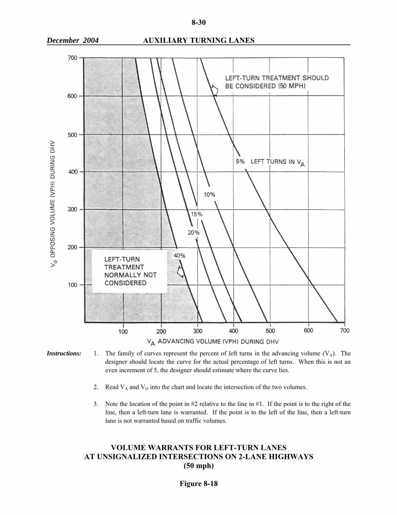
Instructions: 1. The family of curves represent the percent of left turns in the advancing volume (VA). The
designer should locate the curve for the actual percentage of left turns. When this is not an even increment of 5, the designer should estimate where the curve lies.
2. Read VA and VO into the chart and locate the intersection of the two volumes. 3. Note the location of the point in #2 relative to the line in #1. If the point is to the right of the
line, then a left-turn lane is warranted. If the point is to the left of the line, then a left-turn lane is not warranted based on traffic volumes.
VOLUME WARRANTS FOR LEFT-TURN LANES AT UNSIGNALIZED INTERSECTIONS ON 2-LANE HIGHWAYS
(50 mph)
Figure 8-18
8-31 December 2004 AUXILIARY TURNING LANES
Instructions: 1. The family of curves represent the percent of left turns in the advancing volume (VA). The
designer should locate the curve for the actual percentage of left turns. When this is not an even increment of 5, the designer should estimate where the curve lies.
4. Read VA and VO into the chart and locate the intersection of the two volumes. 5. Note the location of the point in #2 relative to the line in #1. If the point is to the right of the
line, then a left-turn lane is warranted. If the point is to the left of the line, then a left-turn lane is not warranted based on traffic volumes.
VOLUME WARRANTS FOR LEFT-TURN LANES AT UNSIGNALIZED INTERSECTIONS ON 2-LANE HIGHWAYS
(40 mph)
Figure 8-19
8-32 December 2004 AUXILIARY TURNING LANES
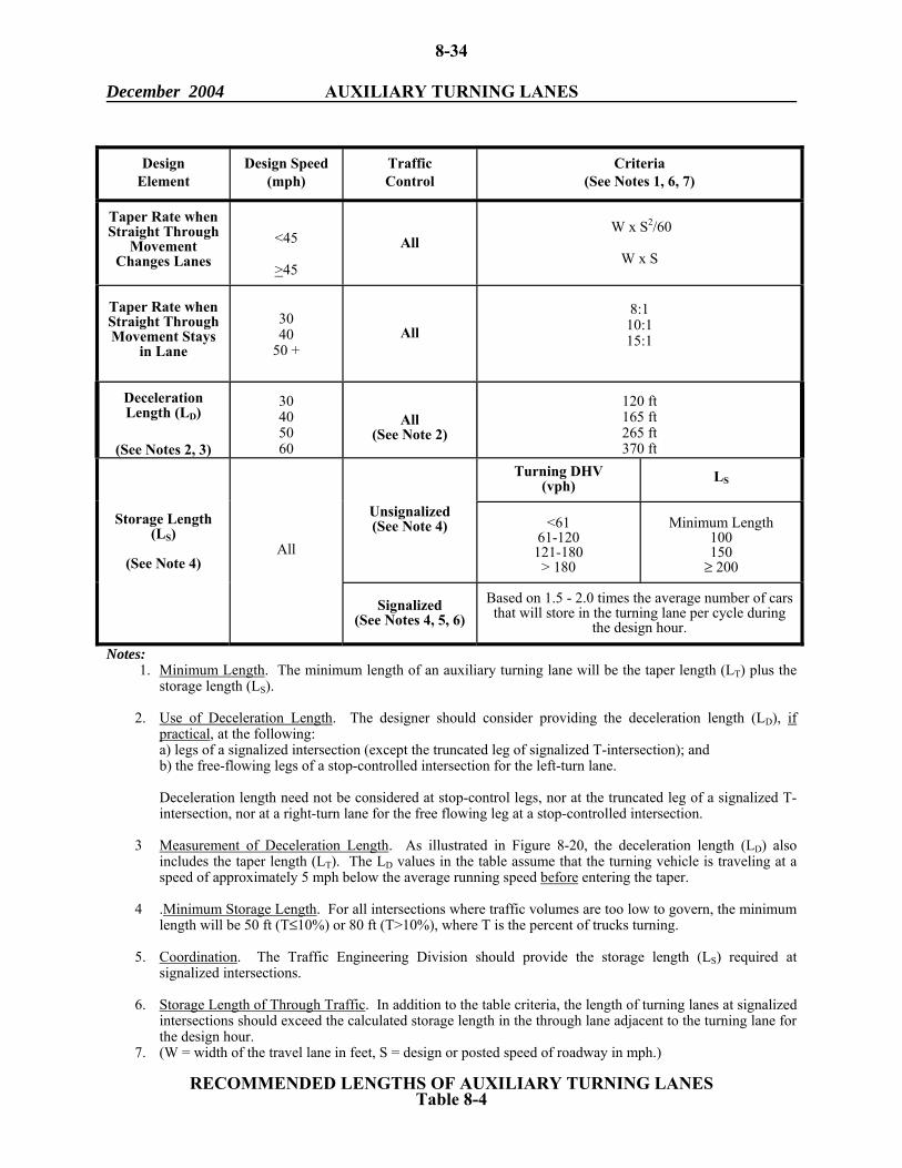
8-4.03 Design of Auxiliary Turning Lanes The following criteria will apply to the design of auxiliary turning lanes: 1. Length. Figure 8-20 illustrates a schematic of auxiliary lanes at an intersection. Table 8-
4 presents the criteria for determining the length of the turning lane. 2. Width. The width of the turn lane should be according to the functional class, urban/rural
location and project scope of work. Chapters Seven and Eleven present the applicable widths for auxiliary lanes, and they present the criteria for shoulder/curb offset width from the auxiliary lane.
3. Parking Lanes. A right-turn lane in an urban area will often require parking restrictions
beyond the typical restricted distance from the intersection. Also, it may require relocating nearside bus stops to the far side of the intersection.
8-4.04 Bypass Lanes Figure 8-21 illustrates the typical design for a bypass lane. This is a relatively inexpensive design to provide for through and left-turn movements at intersections. The bypass lane is appropriate for T-intersections (signalized or unsignalized) where left-turning volumes are light to moderate. It may also be appropriate at 4-way intersections; however, if right-turn volumes are high enough to warrant a right-turn lane (see Figure 8-16), do not use a bypass lane. The decision to use either a channelized left-turn lane or the bypass lane will be based on comparative costs, accident history, right-of-way availability, through and turning traffic volumes, design speed and available sight distance. 8-4.05 Dual Turn Lanes Warrants Dual right- and/or left-turn lanes should be considered when: 1. there is not sufficient space to provide the necessary length of a single turn lane because
of restrictive site conditions (e.g., closely spaced intersections); 2. the necessary length of a single turn lane becomes prohibitive; or
8-33 December 2004 AUXILIARY TURNING LANES
Note: The schematic of the major road (free flowing) also applies to all legs of a signalized intersection.
Notes: 1. Minimum Length. The minimum length of an auxiliary turning lane will be the taper length (LT) plus the
storage length (LS). 2. Use of Deceleration Length. The designer should consider providing the deceleration length (LD), if
practical, at the following: a) legs of a signalized intersection (except the truncated leg of signalized T-intersection); and b) the free-flowing legs of a stop-controlled intersection for the left-turn lane.
Deceleration length need not be considered at stop-control legs, nor at the truncated leg of a signalized T-intersection, nor at a right-turn lane for the free flowing leg at a stop-controlled intersection.
3 Measurement of Deceleration Length. As illustrated in Figure 8-20, the deceleration length (LD) also
includes the taper length (LT). The LD values in the table assume that the turning vehicle is traveling at a speed of approximately 5 mph below the average running speed before entering the taper.
4 .Minimum Storage Length. For all intersections where traffic volumes are too low to govern, the minimum
length will be 50 ft (T≤10%) or 80 ft (T>10%), where T is the percent of trucks turning. 5. Coordination. The Traffic Engineering Division should provide the storage length (LS) required at
signalized intersections. 6. Storage Length of Through Traffic. In addition to the table criteria, the length of turning lanes at signalized
intersections should exceed the calculated storage length in the through lane adjacent to the turning lane for the design hour.
7. (W = width of the travel lane in feet, S = design or posted speed of roadway in mph.)
RECOMMENDED LENGTHS OF AUXILIARY TURNING LANES Table 8-4
Design Element
Design Speed (mph)
Traffic Control
Criteria (See Notes 1, 6, 7)
Taper Rate when Straight Through
Movement Changes Lanes
<45
>45
All W x S2/60
W x S
Taper Rate when Straight Through Movement Stays
in Lane
30 40
50 +
All
8:1
10:1 15:1
Deceleration Length (LD)
(See Notes 2, 3)
30 40 50 60
All
(See Note 2)
120 ft 165 ft 265 ft 370 ft
Turning DHV
(vph)
LS
Unsignalized (See Note 4) <61
61-120 121-180
> 180
Minimum Length
100 150
≥ 200
Storage Length (LS)
(See Note 4)
All
Signalized (See Notes 4, 5, 6)
Based on 1.5 - 2.0 times the average number of cars that will store in the turning lane per cycle during
the design hour.
8-35 December 2004 AUXILIARY TURNING LANES
TYPICAL BYPASS LANE ON A TWO-LANE HIGHWAY
Figure 8-21
8-36 December 2004 AUXILIARY TURNING LANES 3. the necessary time for a protected left-turn phase for a single lane becomes unattainable
to meet the level-of-service criteria (average delay per vehicle). Dual right-turn lanes do not work as well as dual left-turn lanes because of the more restrictive turning movements for two abreast right turns. If practical, the designer should find an alternative means to accommodate a high number of right-turning vehicles. For example, a turning roadway may accomplish this purpose. Design For dual turning lanes to work properly, several design elements must be carefully evaluated. Figure 8-22 presents both dual right- and left-turn lanes to illustrate the more important design elements. The designer should consider the following: 1. Throat Width. Because of the off-tracking characteristics of turning vehicles, the normal
width of two travel lanes may be inadequate to properly receive two vehicles turning abreast. Therefore, the receiving throat width may need to be widened. The throat width will be determined by the application of the turning templates for the design vehicles (see No. 5). The designer can expect that the width for dual turn lanes will be approximately 30-36 feet. When determining the available throat width, the designer can assume that a paved shoulder, if present at the receiving throat, will be used to accommodate two-abreast turns.
2. Widening Approaching Through Lanes. If a widened throat width is provided to
receive dual turn lanes, the designer should also consider how this will affect the traffic approaching from the other side. The approach to the intersection should desirably be within 6 feet of the throat width. The designer should also ensure that the through lanes line up relatively well to allow a smooth flow of traffic through the intersection. The decision on a widened approach and pavement markings should be coordinated with the Traffic Engineering Division.
3. Special Pavement Markings. As illustrated in Figure 8-22, these can effectively guide
two lines of vehicles turning abreast. The Traffic Engineering Division will determine the selection and placement of any special pavement markings.
4. Opposing Left-Turn Traffic. If simultaneous, opposing dual left turns will be allowed,
the designer should ensure that there is sufficient space for all turning movements. This is a
8-37 December 2004 AUXILIARY TURNING LANES
DESIGN OF DUAL TURN LANES
Figure 8-22
8-38 December 2004 AUXILIARY TURNING LANES factor at all signalized intersections, but dual left-turn lanes with their two-abreast
vehicles can cause special problems. If space is unavailable, it may be necessary to alter the signal phasing to allow the two directions of traffic to move through the intersection on separate phases. The intersection layout will be coordinated with the Traffic Engineering Division.
5. Turning Templates. All intersection design elements for dual turn lanes must be checked
by using the applicable turning templates. The designer should assume that the WB-62 design vehicle will turn from the inside lane of the dual turn lane, which is the more difficult turning maneuver. The other vehicle can be assumed to be a passenger vehicle turning side by side with the WB-62.
8-39 December 2004 CONTINUOUS TWO-WAY LEFT-TURN LANES 8-5 CONTINUOUS TWO-WAY LEFT-TURN LANES Continuous two-way left-turn lanes (CTWLTL) are used as a cost-effective method to accommodate a continuous left-turn demand and to reduce delay and accidents. These lanes will often improve operations on roadways which were originally intended to serve the through movement but now must accommodate the demand for accessibility created by changes in adjacent land use. All proposed locations and proposed design details for a CTWLTL should be coordinated with the Traffic Engineering Division. 8-5.01 Warrants Functional Class An undivided 2-lane or 4-lane urban arterial is the most common candidate for the implementation of a CTWLTL. Traffic Volumes Traffic volumes are a significant factor in the consideration of a CTWLTL. As general guidance, the following should be used: 1. On existing 2-lane roadways, a CTWLTL will often be advantageous for traffic volumes
between 5,000 and 12,500 AADT. 2. On existing 4-lane highways, a CTWLTL will often be advantageous for traffic volumes
between 10,000 and 25,000 AADT. For traffic volumes greater than 25,000 AADT, a raised median may be the more advantageous design selection.
Pedestrian crossing volumes are also a consideration because of the large paved area which must be traversed when a CTWLTL is present. Speed The design speed on a highway facility is a major factor in CTWLTL applications. Experience indicates that design speeds from 25 mph to 45 mph will properly accommodate a CTWLTL.
8-40 December 2004 CONTINUOUS TWO-WAY LEFT-TURN LANES Design speeds higher than 45 mph may cause concern because of a possible increased accident potential. Accident History On high-volume urban arterials, traffic conflicts often result because of a significant number of mid-block left turns combined with significant opposing traffic volumes. This may lead to disproportionate numbers of mid-block, rear-end and sideswipe accidents. A CTWLTL is likely to reduce these types of accidents. The designer should review and evaluate the available accident data to determine if unusually high numbers of these accidents are occurring. Adjacent Land Use The mid-block, rear-end and sideswipe accidents usually result from high-density, strip commercial development along the highway. This type of land use will normally generate left turns throughout the day. 8-5.02 Design Criteria Lane Width Recommended lane widths for a CTWLTL and various design speeds are presented in Chapters Seven and Eleven. Existing highways that warrant the installation of a CTWLTL are often located in areas of restricted right-of-way. Conversion of the existing cross section may be difficult. To obtain the CTWLTL width, the design may have to consider several alternatives including: 1. removing an existing raised median, 2. reducing the width of existing through lanes, 3. reducing the number of existing through lanes, 4. eliminating existing parking lanes, 5. eliminating or reducing the width of existing shoulders, and/or 6. acquiring additional right-of-way to expand the pavement width by the amount needed
for the CTWLTL.
8-41 December 2004 CONTINUOUS TWO-WAY LEFT-TURN LANES Intersection Treatment At all intersections with public roads, the CTWLTL must either 1) be terminated in advance to allow the development of an exclusive left-turn lane or 2) be extended up to the intersection area. In most cases where the CTWLTL is extended up to the intersection, the pavement marking will switch from two opposing left-turn arrows to one left-turn arrow only. When determining the intersection treatment, the following should be considered: 1. Functional Classification. All intersecting arterials and many collectors will warrant an
exclusive left-turn lane. The majority of intersecting local streets and some collector streets may not warrant an exclusive left-turn lane.
2. Turning Volumes. The left-turn demand into the intersecting road is a factor in
determining the proper intersection treatment. The following may be used as general guidance: If the minimum storage length will govern (Section 8-4.03), then it will probably be warranted to extend the CTWLTL up to the intersection (i.e., provide no exclusive left-turn lane).
3. Minimum Length of CTWLTL. The CTWLTL should have sufficient length to operate
properly, and the type of intersection treatment will determine the length of the CTWLTL. The minimum length will be influenced by through traffic volumes, turning volumes and operating speeds on the highway. The following guidance may be used:
a. On facilities where V ≤ 30 mph and/or lower traffic volumes exist, the recommended
uninterrupted length of a CTWLTL should be 300-500 feet.
b. On facilities where V > 30 mph and/or higher traffic volumes exist, the recommended uninterrupted length of a CTWLTL should be 500-800 feet.
The final decision on the length of the CTWLTL will be based on site conditions.
4. Operational/Safety Factors. Extending the CTWLTL up to an intersection could result in operational or safety problems. Some drivers may, for example, pass through the intersection in the CTWLTL and turn left beyond the intersection into a driveway which is very close to the intersection (e.g., within 100 feet). If operational or safety problems are known or anticipated at an intersection, this is a factor in determining the proper intersection treatment.
8-42 December 2004 CONTINUOUS TWO-WAY LEFT-TURN LANES Transition Transitions may be required at the beginning and ending of a CTWLTL. The length of transition should be computed by using the following equations: 1. L = WS (S>45 mph) 2. L = WS2/60 (S≤45 mph) where:
L = length of transition, ft W = width of transition, ft S = design speed, mph
In most cases, W will be equal to one-half the width of the CTWLTL. Traffic Control Devices A CTWLTL requires proper signing and pavement markings to reduce indecision and misuse. Criteria for signing and markings are presented in the MUTCD. The Traffic Engineering Division will determine the proper application of traffic control devices
8-43 December 2004 MEDIAN OPENINGS 8-6 MEDIAN OPENINGS 8-6.01 Warrants Non-Freeways Desirably, median openings will be provided on divided non-freeways at all public roads and major traffic generators (e.g., shopping centers). In urban areas, this may result in close intersection spacing which impairs the operation of the facility. The following should be evaluated when determining the warrant for a median opening on urban arterials: 1. Signalized Intersections. Signalized intersections should be no more closely spaced than
1600 feet. Closer spacings may impair the operation of the signals. 2. Unsignalized Intersections. Median openings at unsignalized intersections will depend
upon two factors. The width of the median should allow the development of an exclusive left-turn lane; if not, it may be practical to widen the median at the intersection to provide space for a channelized left-turn lane. The spacing of median openings should be large enough to allow the development of an exclusive left-turn lane with the proper length. See Figure 8-23.
Freeways On fully access-controlled freeways, crossovers are needed to accommodate maintenance and emergency vehicles. The following should be considered: 1. Warrants and Location. Crossovers should be placed to facilitate operations such as
snow plowing and considering interchange spacing. The decision on warrants and locations will be made by the Bureau of Maintenance and Operations.
2. Sight Distance. Because of the unexpected U-turn maneuver, sight distances should be
high when vehicles make U-turns on freeways. At a minimum, the sight distance should be 1500 feet to the crossover from both directions.
3. Median Barriers. Emergency crossovers should be avoided where a median barrier is
present. If a crossover must be provided, the barrier should be terminated as described in Section 10-6. The width of the opening should be approximately 25-30 feet
8-44 December 2004 MEDIAN OPENINGS
RECOMMENDED MEDIAN OPENING SPACING (Non-Freeways)
Figure 8-23
RE
CO
MM
EN
DE
D M
ED
IAN
OPE
NIN
G S
PAC
ING
(N
on-F
reew
ays)
Figu
re 8
-23
8-45 December 2004 MEDIAN OPENINGS 8-6.02 Design Figure 8-24 illustrates the turning path for the WB-62 design vehicle, and it illustrates other design criteria at a median opening. The following will apply: 1. Design Vehicle. The WB-62 design vehicle will apply to median openings. 2. Encroachment. Where a single left-turn lane is used, the desirable design will be to
allow the WB-62 to make the left-turn entirely within the inside lane; i.e., there will be no encroachment into the through lane adjacent to the inside lane. It will be acceptable for the WB-62 to occupy both travel lanes in its turn (see Figure 8-23).
3. Median Nose Design. The shape of the nose at median openings depends on the width of
the divider (m) either between the two roadway edges or between the left-turn lane and the opposing roadway edge (see Figure 8-23). This width is in contrast to the median width (M), which is measured between the edges of the two inside lanes and, therefore, includes the width of left-turn lanes, if present, and shoulder/curb offset widths.
The most common types of median noses are the semicircular end and the bullet-nose end. Recommended criteria for the selection of the median end shape based on "m" are provided in Figure 8-24. Although the semicircular design may be used for wider medians, this requires considerably larger lengths of openings.
For the bullet-nose design, a compound curvature arrangement should be used. The radius at the tip of the nose will normally be 2-3 feet with a minimum of 1.5 feet. To determine the flatter radius, the designer should use the turning template of the design vehicle. The designer should then select a nose radius which allows the design vehicle to make the turn while at no time coming closer than 2 feet to the radius line.
4. Length of Opening. The length of a median opening should properly accommodate the
turning path of the design vehicle. The minimum length is 40 feet. The length of opening should be at least 4 feet greater than the width of the intersecting road. Each median opening will be evaluated individually to determine the proper length of opening. The designer should consider the following factors in the evaluation:
a. Turning Templates. The WB-62 will be used to check the length of opening.
b. Inside Clearance. As stated in No. 3, the WB-62 design vehicle should make the turn without coming closer than 2 feet to the median nose
8-46 December 2004 MEDIAN OPENINGS
MEDIAN OPENING DESIGN
Figure 8-24
Med
ian
End
Sha
pe
Sem
icirc
ular
B
ulle
t Nos
e Tr
eate
d as
sepa
rate
inte
rsec
tion
m (f
eet)
m<8
8≤m≤7
0
m>7
0
ME
DIA
N O
PEN
ING
DE
SIG
N
Fi
gure
8-2
4
Not
es:
M
=
med
ian
wid
th (e
dge
of tr
avel
ed w
ay to
edg
e of
trave
led
way
) m
=
w
idth
of m
edia
n di
vide
r (ed
ge o
f sho
ulde
r to
edge
of
sh
ould
er)
8-47 December 2004 MEDIAN OPENINGS
c. Lane Alignment. The designer should ensure that lanes line up properly for
crossing traffic. d. Location of Crosswalks. Desirably, pedestrian crosswalks will intersect the
median nose to provide some refuge for pedestrians. Crosswalk location will be coordinated with the Traffic Engineering Division
8-48 December 2004 CHANNELIZED ISLANDS 8-7 CHANNELIZED ISLANDS Several of the treatments described in this chapter require channelized islands within the intersection areas. These include turning roadways and channelized left-turn lanes. Figure 8-25 illustrates a typical channelization treatment as a T-intersection. Figure 8-26 illustrates several types of channelized islands with the key details for island design. These are discussed in the following sections. 8-7.01 Types of Islands 1. Directional Islands. Directional islands (e.g., for turning roadways) control and direct
traffic movements and guide the driver into the proper channel. 2. Divisional Islands. Divisional islands separate opposing traffic flows, alert the driver to
the crossroad ahead and regulate traffic through the intersection. These islands are often introduced at intersections on undivided highways. The minimum length of divisional islands is 25 feet.
Channelized islands may be some combination of flush or raised, paved or grass, and triangular or elongated. Raised islands formed by curbs should be used where pedestrian traffic is significant, where traffic control devices are needed within the island, and where the design speed is 45 mph and below. 8-7.02 Minimum Size Figure 8-26 indicates minimum sizes for channelized islands. 8-7.03 Delineation/Approach Treatment Channelized islands should be delineated by sloping curb or pavement markings based on their size, location and function.
8-49 December 2004 CHANNELIZED ISLANDS
Sloping
1 Where one road has sloping and the other has vertical curb, 1 marks the point where the switch is made
2 When curb is not present on the major and/or side road leading up to the intersection, 2 marks the
points where curb will begin and end. In these cases, sloping curb will be used. Existing vertical curbs leading up to the intersection will be matched.
TYPICAL CHANNELIZATION TREATMENT (T-Intersection)
Figure 8-25
8-50 December 2004 CHANNELIZED ISLANDS
CHANNELIZED ISLANDS
Figure 8-26
Sloping
8-51 December 2004 ENTRANCE DESIGN 8-8 ENTRANCE DESIGN 8-8.01 Design Criteria Entrance Types (Definitions) 1. Residential. One providing access to a single-family residence or 1-4 residential units. 2. Commercial/Industrial. One providing access to an office, retail or institutional building,
to an apartment building or to a warehouse, truck terminal, etc. Such buildings are customarily serviced by trucks. A centralized retail development, such as a community or regional shopping center, may have one or more driveways especially designed, signed and located to provide access for trucks. These also are classified as commercial/industrial entrances.
Entrance Sight Distance Section 8-1 discusses intersection sight distance (ISD) criteria for intersections with public roads. Desirably, these criteria will also apply to sight distances at entrances. For entrances with low volumes, it is not warranted to explore extraordinary measures to improve sight distance. The designer should check for sight obstructions in the vicinity of the entrance such as large trees or hedgerows. To perform the check, it is reasonable to assume an eye location of approximately 10 feet from the edge of travel lane. Auxiliary Lanes Deceleration and acceleration lanes should be considered at high-volume entrances, especially on high-speed, high-volume arterials. Section 8-4 further discusses the design and warrants for auxiliary lanes, and these also apply to high-volume entrances. In addition to traffic-volume considerations, it may be warranted to provide a right-turn lane into the entrance if the change in grade is abrupt at the entrance.
8-52 December 2004 ENTRANCE DESIGN Side Slopes Driveway side slopes should be the same as the mainline side slope. This applies for a minimum distance of the roadside clear zone for the mainline. Beyond this point, driveway side slopes may be steeper. Material During the preliminary or final field inspection, the Construction Team Member may designate if the project being inspected is in an area of the State where the available gravel is sandy and difficult to compact for a good driving surface. Should this be the case, the designer will select the entrance note that calls for gravel entrances to be constructed of 11 inch Aggregate Subbase Course-Gravel and 3 inch Untreated Aggregate Surface Course and estimate accordingly. This note will be added to the general notes. Drainage At some entrances, the potential may exist for melting water to flow along snowbanks and down the entrance toward a building. To alleviate this, the designer will include a hump at the edge of shoulder for all entrances under these conditions whether or not a curb is present. The design of this hump will be according to the Standard Details. This design may be omitted or modified if excessive right-of-way damage is caused by it or if there is no potential drainage problem. Also, it is not intended for use on undeveloped properties that are served by woods and field entrances Design Vehicle The following design vehicles apply: 1. Residential Entrances. Use the P design vehicle. 2. Commercial/Industrial Entrances. Use the WB-62 design vehicle. The application of a turning template will determine the combination of width and turning radii into the entrance which will accommodate the design vehicle.
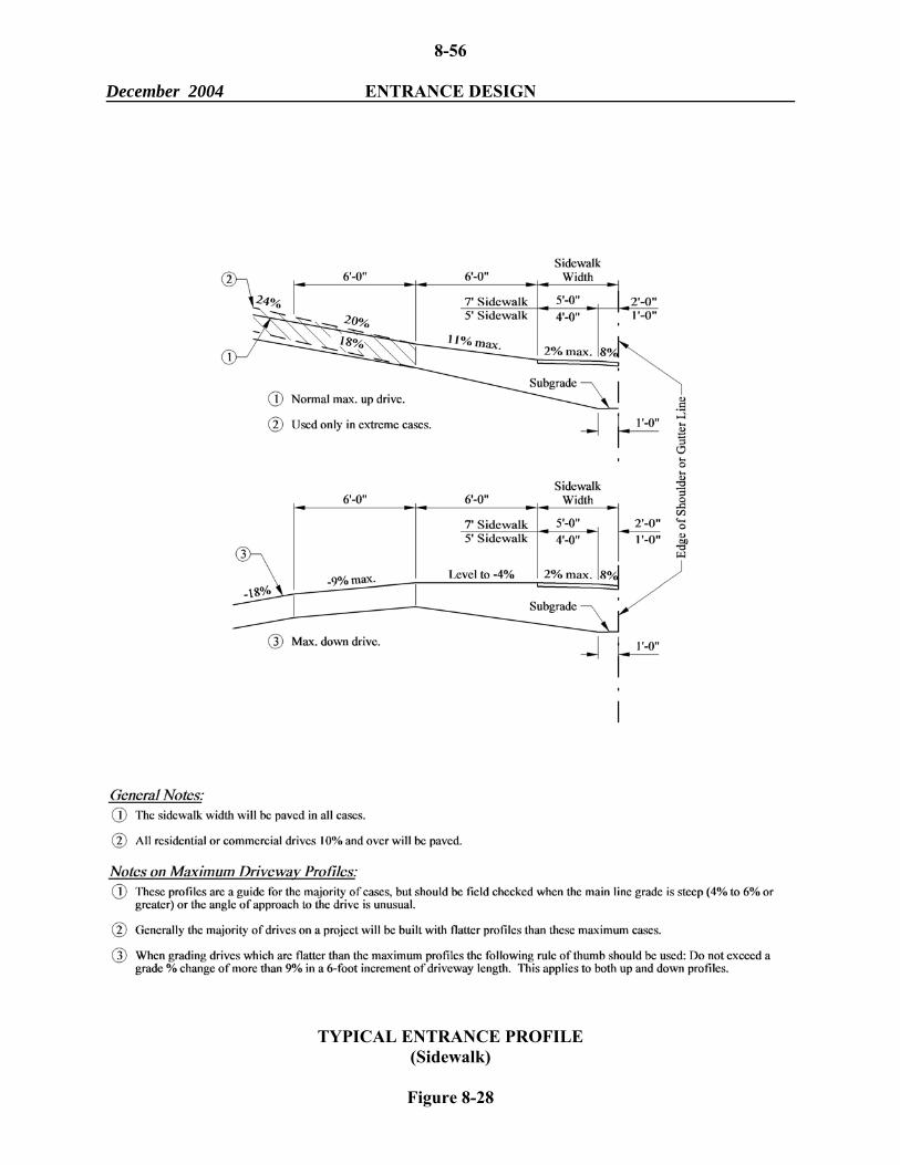
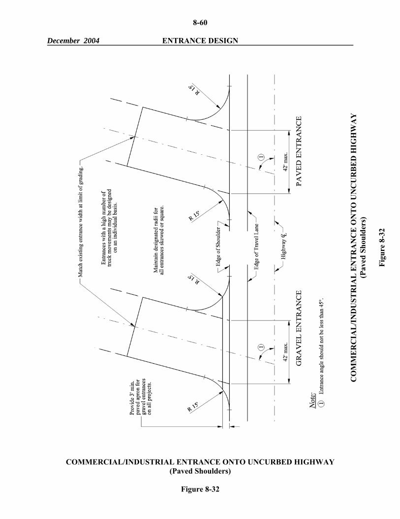
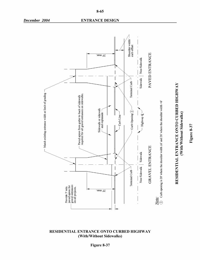
8-53 December 2004 ENTRANCE DESIGN Grades at Skewed Entrances When designing skewed drives, the grade shown is usually along the centerline of the drive. When the skew is sufficiently large, this causes the grade along the inside edge to be considerably steeper than that shown along the centerline and, in a number of cases, will require the resident to lengthen and regrade the entrance. The designer should show grades along the inside edge of all drives that are skewed 30 degrees or more. The inside edge is that edge that forms an acute angle with the roadway. This policy should avoid needing additional grading rights and determining more accurately whether or not a drive should be paved or not because of percent grade. 8-8.02 Entrance Figures Typical Entrance Profiles Figure 8-27 presents design criteria for entrances where no sidewalks exist; Figure 8-28 applies to entrances where sidewalks are present. Typical Entrance Plan Views Typical plan views of entrances are: 1. Figure 8-29 "Residential Entrance onto Uncurbed Highway (Gravel Shoulders)." 2. Figure 8-30 "Residential Entrance onto Uncurbed Highway (Paved Shoulders)." 3. Figure 8-31 "Commercial/Industrial Entrance onto Uncurbed Highway (Gravel
8-71 December 2004 ALIGNMENT/PROFILE 8-9 ALIGNMENT / PROFILE 8-9.01 Alignment The angle of intersection should be within 30 degrees of a 90-degree intersection. Skewed intersections beyond 30 degrees increase the travel distance across the major highway, adversely affect sight distance and complicate the designs for turning movements. If the angle of intersection is not within 30 degrees of a right angle, the intersection should be realigned to 90 degrees, if practical. 8-9.02 Profile Figure 8-43 illustrates profile considerations. The following will apply: 1. Approaching Gradient. The area where vehicles may store on the leg of an intersection
should be as flat as practical. The grade on this landing area (or storage platform) should not exceed 2%, if practical.
2. Stop-Controlled. The profile and cross section of the major road will normally be
maintained through the intersection. The cross section of the stop-controlled road will be transitioned (or warped) to match the major road. The change in gradient on the stop-controlled leg at its entrance into the intersection should not exceed 6%. If it does, the designer should insert a vertical curve approximately 50 feet long to transition from the grade on the minor road to meet the cross slope on the major road.
3. Signal-Controlled. The most desirable option will be to transition all approach legs into a
plane section through the intersection. This will ensure that the vehicles that pass through the intersection will not "bottom out." This may be especially appropriate for arterial/arterial intersections. If this option is not practical, the designer should transition one road to meet the profile and cross section of the other road. The change in gradient on the transitioned leg at its entrance into the intersection should not exceed 4%. If it does, the designer should insert a vertical curve approximately 50 feet long to transition from the grade on the minor road to meet the cross slope on the major road.
4. Drainage. The profile and transitions at all intersections should be evaluated for their
impact on drainage
8-72 December 2004 ALIGNMENT/PROFILE
PROFILES OF INTERSECTING ROADS
Figure 8-43
8-73 December 2004 REFERENCES 8-10 REFERENCES 1. A Policy on Geometric Design of Highways and Streets, AASHTO, 2001. 2. Highway Capacity Manual, Special Report No. 209, Transportation Research Board. 3. Manual on Uniform Traffic Control Devices, National Advisory Committee on Uniform
Traffic Control Devices. 4. Highway Research Board, Special Report No. 74, "Channelization," National Research
Council, 1962. 5. Report No. FHWA-RD-76-86, "Technical Guidelines for the Control of Direct Access to
Arterial Highways," August, 1975. 6. NCHRP 93, "Guidelines for Medial and Marginal Access Control on Major Roadways,"
Highway Research Board, 1970. 7. FHWA Course Notebook, "Safety Design and Operational Practices for Streets and
Highways," Texas Transportation Institute, 1978. 7. "Volume Warrants for Left-Turn Storage Lanes at Unsignalized Grade Intersections,"
M.D. Harmelink, Highway Research Record 211, 1967. 9. Technical Council Information Report, "Design and Use of Two-Way Left-Turn Lanes,"
Institute of Transportation Engineers, ITE Journal, February, 1981. 10. Technical Council Informational Report, "Design Criteria for Left-turn Channelization,"
Institute of Transportation Engineers, ITE Journal, February, 1981. 11. "Guidelines for Treatment of Right-Turn Movements on Rural Roads," Transportation
Research Record 855, 1982. 12. "Development of Guidelines for the Application of Continuous Two-Way Left-Turn
Median Lanes," Final Report - EES470, Zoltan Nemeth, Ohio State University, July, 1976.
13. Technical Council Informational Report, "Effectiveness of Median Storage and
Acceleration Lanes for Left-Turning Vehicles," Institute of Transportation Engineers, ITE Journal, March, 1985.
8-74 December 2004 REFERENCES 14. Institute of Transportation Engineers Recommended Practice, "Guidelines for Driveway
Design and Location," Institute of Transportation Engineers, 1985. 15. NCHRP 279, "Intersection Channelization Design Guide," Transportation Research