Chapter 1 ireless communications have become very pervasive. The number of mobile phones and wireless Internet users has increased significantly in recent years. Tra- ditionally, first-generation wireless networks were targeted primarily at voice and data communications occurring at low data rates. Recently, we have seen the evolution of second- and third-generation wireless systems that incorporate the features provided by broadband. In addition to sup- porting mobility, broadband also aims to support multimedia traffic, with quality of service (QoS) assurance. We have also seen the presence of different air interface technologies, and the need for interoperability has increasingly been recognized by the research community. Wireless networks include local, metropolitian, wide, and global areas. In this chapter, we will cover the evolution of such networks, their basic principles of 1
Transcript
Chapter 1
� � � � � � � � � ��� � � �
� � � � � � � � � � � � � �
�ireless communications have become very pervasive. The number of mobile
phones and wireless Internet users has increased significantly in recent years. Tra-ditionally, first-generation wireless networks were targeted primarily at voice anddata communications occurring at low data rates.
Recently, we have seen the evolution of second- and third-generation wirelesssystems that incorporate the features provided by broadband. In addition to sup-porting mobility, broadband also aims to support multimedia traffic, with quality ofservice (QoS) assurance. We have also seen the presence of different air interfacetechnologies, and the need for interoperability has increasingly been recognized bythe research community.
Wireless networks include local, metropolitian, wide, and global areas. In thischapter, we will cover the evolution of such networks, their basic principles of
The first generation of analog cellular systems included the Advanced Mobile Tele-phone System (AMPS) [1] which was made available in 1983. A total of 40MHzof spectrum was allocated from the 800MHz band by the Federal CommunicationsCommission (FCC) for AMPS. It was first deployed in Chicago, with a service areaof 2100 square miles [2]. AMPS offered 832 channels, with a data rate of 10 kbps.Although omnidirectional antennas were used in the earlier AMPS implementa-tion, it was realized that using directional antennas would yield better cell reuse.In fact, the smallest reuse factor that would fulfill the 18db signal-to-interferenceratio (SIR) using 120-degree directional antennas was found to be 7. Hence, a 7-cell reuse pattern was adopted for AMPS. Transmissions from the base stations tomobiles occur over the forward channel using frequencies between 869-894 MHz.The reverse channel is used for transmissions from mobiles to base station, usingfrequencies between 824-849 MHz.
In Europe, TACS (Total Access Communications System) was introduced with1000 channels and a data rate of 8 kbps. AMPS and TACS use the frequencymodulation (FM) technique for radio transmission. Traffic is multiplexed onto anFDMA (frequency division multiple access) system. In Scandinavian countries, theNordic Mobile Telephone is used.
Compared to first-generation systems, second-generation (2G) systems use digi-tal multiple access technology, such as TDMA (time division multiple access) andCDMA (code division multiple access). Global System for Mobile Communica-tions, or GSM [3], uses TDMA technology to support multiple users.
Examples of second-generation systems are GSM, Cordless Telephone (CT2),Personal Access Communications Systems (PACS), and Digital European CordlessTelephone (DECT [4]). A new design was introduced into the mobile switchingcenter of second-generation systems. In particular, the use of base station con-trollers (BSCs) lightens the load placed on the MSC (mobile switching center)found in first-generation systems. This design allows the interface between theMSC and BSC to be standardized. Hence, considerable attention was devoted tointeroperability and standardization in second-generation systems so that carriers
could employ different manufacturers for the MSC and BSCs.In addition to enhancements in MSC design, the mobile-assisted handoff mech-
anism was introduced. By sensing signals received from adjacent base stations, amobile unit can trigger a handoff by performing explicit signalling with the net-work.
Second generation protocols use digital encoding and include GSM, D-AMPS(TDMA) and CDMA (IS-95). 2G networks are in current use around the world.The protocols behind 2G networks support voice and some limited data commu-nications, such as Fax and short messaging service (SMS), and most 2G protocolsoffer different levels of encryption, and security. While first-generation systemssupport primarily voice traffic, second-generation systems support voice, paging,data, and fax services.
������� Q����F *J�&-.#/�10JK�M�@$!C0)O @
The move into the 2.5G world will begin with General Packet Radio Service (GPRS).GPRS is a radio technology for GSM networks that adds packet-switching proto-cols, shorter setup time for ISP connections, and the possibility to charge by theamount of data sent, rather than connection time. Packet switching is a techniquewhereby the information (voice or data) to be sent is broken up into packets, of atmost a few Kbytes each, which are then routed by the network between differentdestinations based on addressing data within each packet. Use of network resourcesis optimized as the resources are needed only during the handling of each packet.
The next generation of data heading towards third generation and personal mul-timedia environments builds on GPRS and is known as Enhanced Data rate forGSM Evolution (EDGE). EDGE will also be a significant contributor in 2.5G. Itwill allow GSM operators to use existing GSM radio bands to offer wireless mul-timedia IP-based services and applications at theoretical maximum speeds of 384kbps with a bit-rate of 48 kbps per timeslot and up to 69.2 kbps per timeslot in goodradio conditions. EDGE will let operators function without a 3G license and com-pete with 3G networks offering similar data services. Implementing EDGE will berelatively painless and will require relatively small changes to network hardwareand software as it uses the same TDMA (Time Division Multiple Access) framestructure, logic channel and 200 kHz carrier bandwidth as today’s GSM networks.As EDGE progresses to coexistence with 3G WCDMA, data rates of up to ATM-like speeds of 2 Mbps could be available.
GPRS will support flexible data transmission rates as well as continuous con-nection to the network. GPRS is the most significant step towards 3G.
Third-generation mobile systems are faced with several challenging technical is-sues, such as the provision of seamless services across both wired and wirelessnetworks and universal mobility. In Europe, there are three evolving networks un-der investigation: (a) UMTS (Universal Mobile Telecommunications Systems), (b)MBS (Mobile Broadband Systems), and (c) WLAN (Wireless Local Area Net-works).
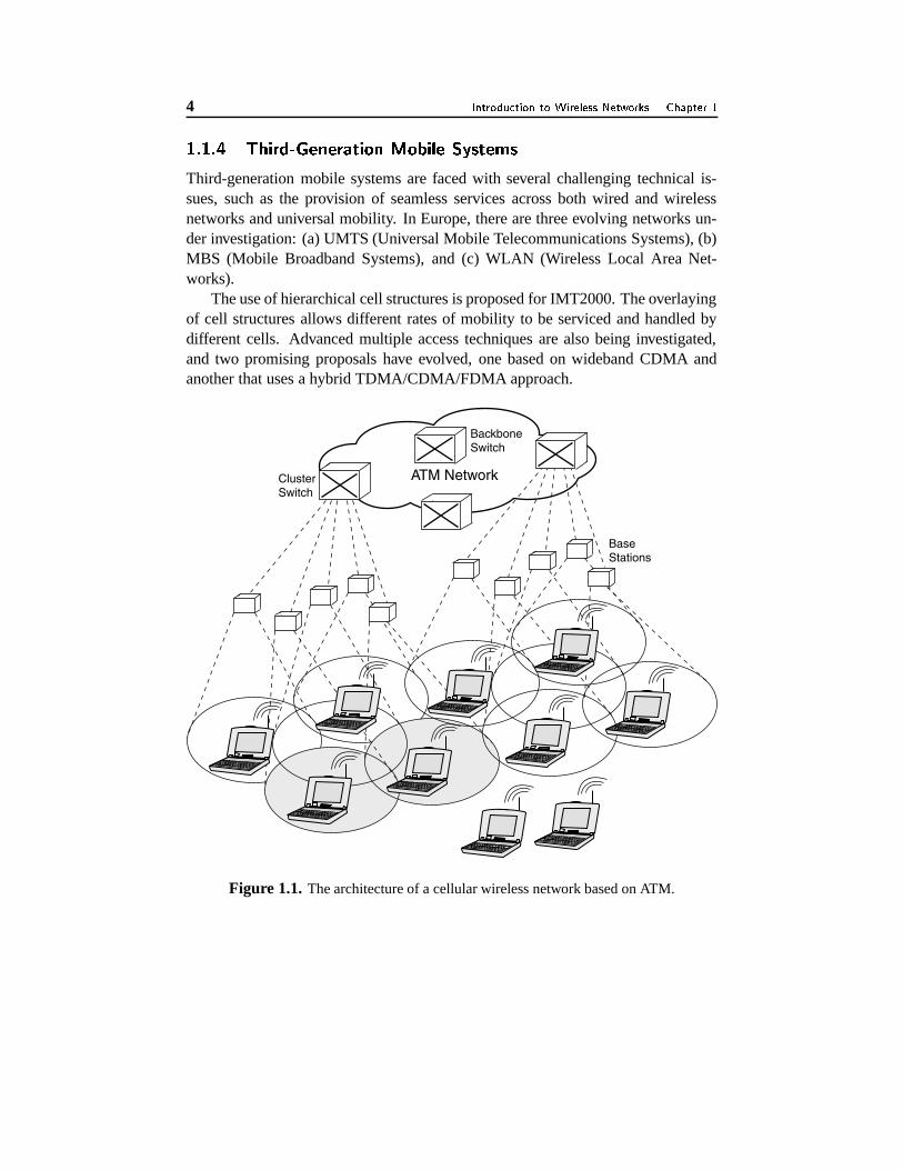
The use of hierarchical cell structures is proposed for IMT2000. The overlayingof cell structures allows different rates of mobility to be serviced and handled bydifferent cells. Advanced multiple access techniques are also being investigated,and two promising proposals have evolved, one based on wideband CDMA andanother that uses a hybrid TDMA/CDMA/FDMA approach.
Base Stations
Backbone Switch
Cluster Switch
ATM Network
Figure 1.1. The architecture of a cellular wireless network based on ATM.
���/Q F �1�&-57.� K�M�@C!C0)O (��8+*J�&-.#/�10,24�&O O ��%.#6RS7�!$#��&%.@ �$F K *��
GSM is commonly referred to as the second-generation mobile cellular system.GSM has its own set of communication protocols, interfaces, and functional enti-ties. It is capable of supporting roaming, and carrying speech and data traffic.
Public Network
Base Station and �Mobile Subsystems
HLR VLR AUC
MSC
EIR
Network Switching Subsystem
BSC
BSC
ISDN
Data Networks
PSTN
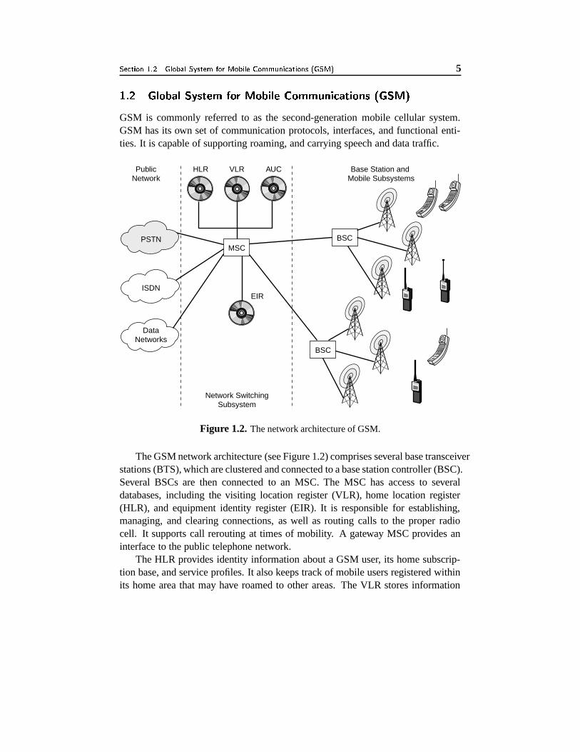
Figure 1.2. The network architecture of GSM.
The GSM network architecture (see Figure 1.2) comprises several base transceiverstations (BTS), which are clustered and connected to a base station controller (BSC).Several BSCs are then connected to an MSC. The MSC has access to severaldatabases, including the visiting location register (VLR), home location register(HLR), and equipment identity register (EIR). It is responsible for establishing,managing, and clearing connections, as well as routing calls to the proper radiocell. It supports call rerouting at times of mobility. A gateway MSC provides aninterface to the public telephone network.
The HLR provides identity information about a GSM user, its home subscrip-tion base, and service profiles. It also keeps track of mobile users registered withinits home area that may have roamed to other areas. The VLR stores information
about subscribers visiting a particular area within the control of a specific MSC.The authentication center (AC) is used to protect subscribers from unauthorized
access. It checks and authenticates when a user powers up and registers with thenetwork. The EIR is used for equipment registration so that the hardware in usecan be identified. Hence if a device is stolen, service access can be denied by thenetwork. Also, if a device has not been previously approved by the network vendor(perhaps subject to the payment of fees by the user), EIR checks can prevent thedevice from accessing the network.
In GSM, each mobile device is uniquely identified by an IMSI (internationalmobile subscriber identity). It identifies the country in which the mobile systemresides, the mobile network, and the mobile subscriber. The IMSI is stored on asubscriber identity module (SIM), which can exist in the form of a plug-in moduleor an insertable card. With a SIM, a user can practically use any mobile phone toaccess network services.
The GSM general packet radio service (GPRS) is a data overlay over the voice-based GSM cellular network. It consists of a packet wireless access network andan IP-based backbone. GPRS is designed to transmit small amounts of frequentlysent data or large amounts of infrequently sent data. GPRS has been seen as anevolution toward UMTS (Universal Mobile Telecommunications Systems). Userscan access IP services via GPRS/GSM networks.
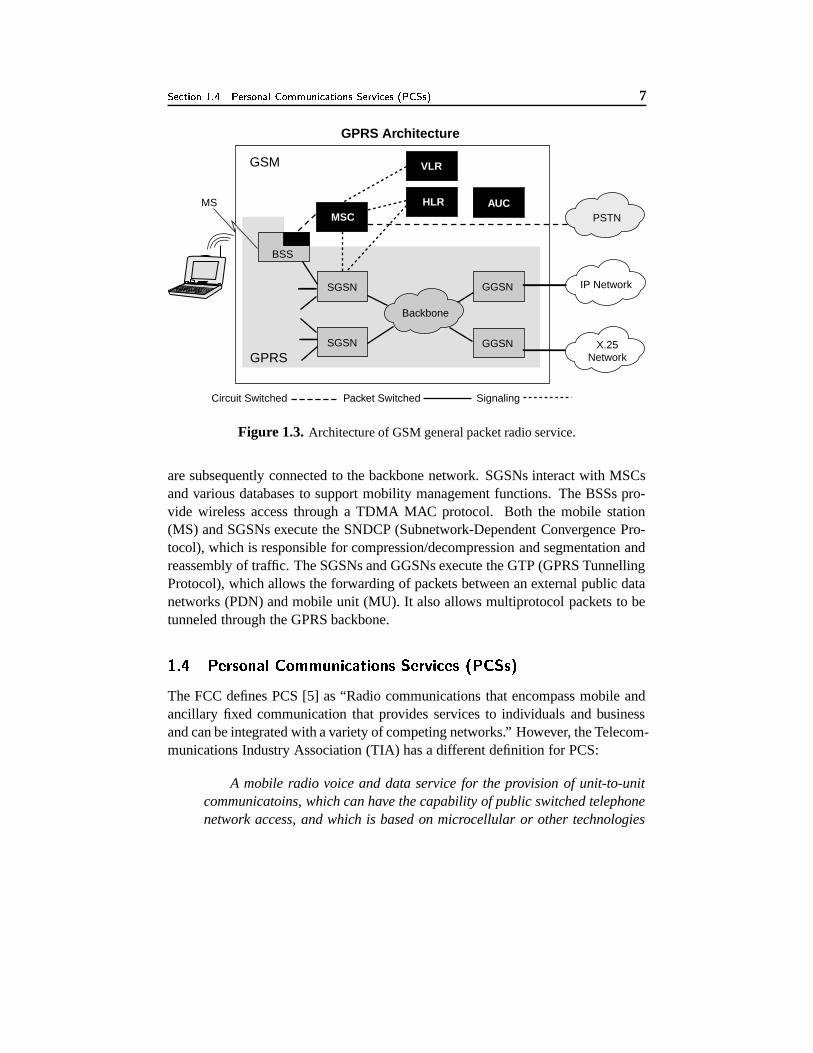
GPRS services include both point-to-point and point-to-multipoint communi-cations. The network architecture of GPRS is shown in Figure 1.3. Gateway GSN(GGSN) nodes provide interworking functions with external packet-switched net-works. A serving GPRS support node (SGSN), on the other hand, keeps trackof an individual mobile station’s location and provides security and access con-trol. As shown in Figure 1.3, base stations (BSSs) are connected to SGSNs, which
Figure 1.3. Architecture of GSM general packet radio service.
are subsequently connected to the backbone network. SGSNs interact with MSCsand various databases to support mobility management functions. The BSSs pro-vide wireless access through a TDMA MAC protocol. Both the mobile station(MS) and SGSNs execute the SNDCP (Subnetwork-Dependent Convergence Pro-tocol), which is responsible for compression/decompression and segmentation andreassembly of traffic. The SGSNs and GGSNs execute the GTP (GPRS TunnellingProtocol), which allows the forwarding of packets between an external public datanetworks (PDN) and mobile unit (MU). It also allows multiprotocol packets to betunneled through the GPRS backbone.
The FCC defines PCS [5] as “Radio communications that encompass mobile andancillary fixed communication that provides services to individuals and businessand can be integrated with a variety of competing networks.” However, the Telecom-munications Industry Association (TIA) has a different definition for PCS:
A mobile radio voice and data service for the provision of unit-to-unitcommunicatoins, which can have the capability of public switched telephonenetwork access, and which is based on microcellular or other technologies
that enhance spectrum capacity to the point where it will offer the potentialof essentially ubiquitous and unlimited, untethered communications.
PCS can also be defined in a broader sense [6] as a set of capabilities thatallows some combination of personal mobility and service management. In short,PCS [7] is a commonly used term that defines the next generation of advancedwireless networks providing personalized communication services. In Europe, theterm “personal communication networks (PCNs)” is used instead of PCS.
The basic requirements for a PCS are:
� Users must be able to make calls wherever they are
� Offered services must be reliable and of good quality
� Provision of multiple services such as voice, fax, video, paging, etc., must beavailable.
Unlike AMPS, PCS is aimed at the personal consumer industry for mass con-sumption. The FCC’s view of PCS is one where the public switched telephonenetwork (PSTN) is connected to a variety of other networks, such as CATV (cabletelevision), AMPS cellular systems, etc.
���� � #�8H05�10"@$@���� 9;@ ������� 9 K �
Wireless LAN technology has evolved to extend to existing wired networks. Localarea networks (LANs) are mostly based on Ethernet media access technology thatconsists of an interconnection of hosts and routers. LANs are restricted by distance.They are commonly found in offices and inside buildings. Interconnection usingwires can be expensive when it comes to relocating servers, printers, and hosts.
Now, more wireless LANs (WLANs) are being deployed in offices. MostWLANs are compatible with Ethernet, and hence, there is no need for protocolconversion. The IEEE has standardized 802.11 protocols to support WLANs me-dia access. A radio base station can be installed in a network to serve multiplewireless hosts over 100-200 m. A host (for example, a laptop) can be wirelesslyenabled by installing a wireless adapter and the appropriate communication driver.A user can perform all network-related functions as long as he or she is within thecoverage area of the radio base station. This gives the user the capability to performwork beyond his or her office space.
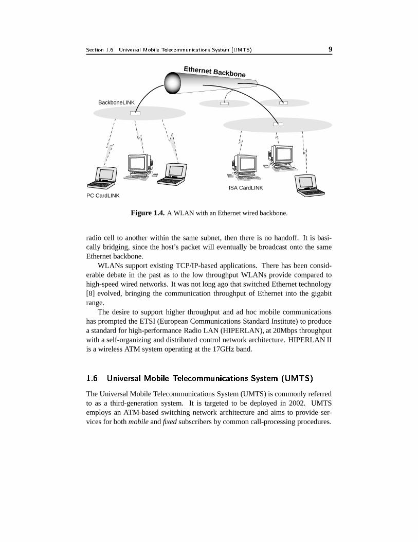
As shown in Figure 1.4, several overlapping radio cells can be used to providewireless connectivity over a desired region. If a wireless host migrates from one
Figure 1.4. A WLAN with an Ethernet wired backbone.
radio cell to another within the same subnet, then there is no handoff. It is basi-cally bridging, since the host’s packet will eventually be broadcast onto the sameEthernet backbone.
WLANs support existing TCP/IP-based applications. There has been consid-erable debate in the past as to the low throughput WLANs provide compared tohigh-speed wired networks. It was not long ago that switched Ethernet technology[8] evolved, bringing the communication throughput of Ethernet into the gigabitrange.
The desire to support higher throughput and ad hoc mobile communicationshas prompted the ETSI (European Communications Standard Institute) to producea standard for high-performance Radio LAN (HIPERLAN), at 20Mbps throughputwith a self-organizing and distributed control network architecture. HIPERLAN IIis a wireless ATM system operating at the 17GHz band.
����� �;%.#1��0�8H@$7)� *,�&-.#/�10 � 0.�10"RS�&O O ��%.#6RS7�!$#��&%5@ K�M�@C!C0)O �� * � K �
The Universal Mobile Telecommunications System (UMTS) is commonly referredto as a third-generation system. It is targeted to be deployed in 2002. UMTSemploys an ATM-based switching network architecture and aims to provide ser-vices for both mobile and fixed subscribers by common call-processing procedures.
The UMTS architecture is split into core (switching) networks, control (service)networks, and access networks. The core network is responsible for perform-ing switching and transmission functions. The control network supports roamingthrough the presence of mobility management functions. Finally, the radio accessnetwork provides channel access to mobile users and performs radio resource man-agement and signalling. UMTS will include both terrestrial and global satellitecomponents.
The UMTS network comprises: (a) the mobile terminal, (b) the base transceiverstation (BTS), (c) the cell site switch (CSS), (d) mobile service control points(MSCP), and (e) the UMTS mobility service (UMS). UMTS employs a hierarchicalcell structure, with macrocells overlaying microcells and picocells. Highly mobiletraffic is operated on the macrocells to reduce the number of handoffs required.UMTS aims to support roaming across different networks.
The UMTS Radio Access System (UTRA) will provide at least 144 kbps forfull-mobility applications, 384 kbps for limited-mobility applications, and 2.048Mbps for low-mobility applications. UMTS terminals will be multiband and mul-timode so that they can work with different standards.
UMTS is also designed to offer data rate on-demand. The network will reactto a user’s needs, based on his/her profile and current resource availability in thenetwork. UMTS supports the virtual home environment (VHE) concept, where apersonal mobile user will continue to experience a consistent set of services evenif he/she roams from his/her home network to other UMTS operators. VHE sup-ports a consistent working environment regardless of a user’s location or mode ofaccess. UMTS will also support adaptation of requirements due to different datarate availability under different environments, so that users can continue to use theircommunication services.
To support universal roaming and global coverage, UMTS will include bothterrestrial and satellite systems. It will enable roaming with other networks, suchas GSM. UMTS will provide a flexible broadband access technology that supportsboth IP and non-IP traffic in a variety of modes, such as packet, circuit-switched,and virtual circuit.
��� � � * � Q������
The ITU (International Telecommunications Union) has introduced a new frame-work of standards by the name IMT2000, which is a federation of systems forthird-generation mobile telecommunications. IMT2000 aims to provide: (a) high-speed access, (b) support for broadband multimedia services, and (c) universal mo-
bility. Frequency spectrum has been allocated for IMT2000 by the ITU. Severalmultiple-access protocols based on code division have been proposed by many dif-ferent countries. The ITU has approved the CDMA2000 radio access system asthe CDMA multicarrier member of the IMT2000 family of standards. CDMA2000is capable of supporting IS-41 and GSM-MAP to ensure backward compatibility.IS-41 is a network protocol standard that supports interoperator roaming [2]. Itallows MSCs of different service providers to exchange information about theirsubscribers to other MSCs on-demand.
The IS-95 [9] air interface was standardized by TIA in July 1993. Networks that uti-lize IS-95 CDMA [10] air interface and the ANSI-41 network protocol are knownas cdmaOne networks. IS-95 networks use one or more 1.25 MHz carriers andoperate within the 800 and 1900 MHz frequency bands.
Following the launch of the first cdmaOne network in Hong Kong in 1995,the number of cdmaOne subscribers has grown into millions. cdmaOne networksprovide soft handoffs and higher capacity than traditional AMPS networks, withdata rates up to 14.4 kbps. CdmaOne is based on IS-95A technology. IS-95Bimproves this technology further by providing higher data rates for packet- andcircuit-switched CDMA data, with data rates up to 115 kbps.
This evolution continues with cdma2000, which is the third generation verionof IS-95. This new standard is developed to support third generation services asdefined by ITU. cdma2000 is divided into two parts, namely: (a) IS-2000/cdma2001X, and (b) IS-2000A/cdma2000 3X. cdma2000 1X standard delivers twice thevoice capacity of cdmaOne with a data rate of 144 kbps. The term 1X, as derivedfrom 1XRTT (radio transmission technology), is used to signify that the standardcarrier on the air interface is 1.25 MHz, which is similar to IS-95A and IS-95B. Incdma2000 3x, the term 3X, derived from 3XRTT, is used to signify three times 1.25MHz, i.e., 3.75 MHz. cdma2000 3X offers greater capacity than 1X with data ratesup to 2 Mbps while retaining backward compatibility with earlier 1X and cdmaOnedeployments.
Lately, 3GPP (Third Generation Partnership Project) [11] is formed to definedstandards for third generation all-IP networks. It is also responsible for the pro-duction of globally applicable technical specifications and reports for a 3G mobilesystem based on evolved GSM core networks and the radio access technologiesthat they support (i.e., Universal Terrestrial Radio Access (UTRA) both FrequencyDivision Duplex (FDD) and Time Division Duplex (TDD) modes).
This book is organized in a manner that allows a gradual progression of the subjecttoward more advanced topics. Chapter 2 discusses the origin of ad hoc networks, inpaticular, the DARPA packet radio networks. Chapter 3 presents a current versionof ad hoc networks and related challenges. Since there are no static base stationspresent in ad hoc wireless networks, centralized access control becomes a problem.Chapter 4 presents current channel access protocols and discusses some emergingprotocols. Chapter 5 provides an overview of current ad hoc mobile routing proto-cols, discussing their principles, features, and operation. Chapter 6 presents a newera of routing known as longevity, or associativity-based routing. This protocolis a major deviation from traditional routing protocols, which use shortest path asthe main routing metric. Chapter 7 provides a narration of the implementation ofan ad hoc wireless network using a new routing protocol and current-off-the-shelf(COS) hardware. It also provides a discussion of the experimental results obtainedvia campus field trials. Chapter 8 continues with a discussion of the communica-tion performance of ad hoc wireless networks so that readers can understand thecapabilities of such networks and what potential applications can be supported.
The advancement in CPU technology has way surpassed that of battery technol-ogy. Hence, Chapter 9 discusses how device power life can affect communicationperformance and protocol design for ad hoc wireless networks. Multicasting hasbeen widely used to support multiparty communications and conferencing. Chap-ter 10 provides insight on how ad hoc mobile multicasting can be achieved andpresents a survey of current multicasting protocols. It also reveals how associativ-ity or longevity can be applied to ad hoc multicasting.
Since the Internet Protocol (IP) provides unreliable datagram delivery, trans-mission control protocol has been introduced to provide reliable delivery of infor-mation over the internet. Chapter 11 discusses the problems associated with TCP inan ad hoc wireless network environment. Ad hoc networks should provide servicesto users. Chapter 12 presents existing service discovery protocols that will allow anad hoc mobile host to discover services present in the network and to access suchservices.
Commercial realization of ad hoc networks has taken the form of Bluetooth.Chapter 13, therefore, presents a case study of this technology. Prior to the arrivalof Bluetooth, the Wireless Access Protocol (WAP) was a popular technology sinceit enabled a cellular network to support data in addition to voice traffic. Chapter 14,therefore, provides a discussion of WAP. Many people have been wondering aboutthe potential applications of ad hoc networking; Chapter 15 addresses this issue. Aconclusion is finally presented in Chapter 16.