CHAPTER 1 Resource Allocation for Wireless Communication Networks with RF Energy Harvesting Elena Boshkovska Friedrich-Alexander-University Erlangen-N¨ urnberg (FAU), Germany Derrick Wing Kwan Ng The University of New South Wales, Australia Robert Schober Friedrich-Alexander-University Erlangen-N¨ urnberg (FAU), Germany CONTENTS 1.1 Introduction ...................................................................... 3 1.2 Receiver Structure ............................................................... 5 1.3 SWIPT Communication Networks ............................................... 6 1.3.1 Channel Model ........................................................... 7 1.3.2 Non-linear Energy Harvesting Model .................................... 7 1.3.3 Channel State Information ............................................... 9 1.3.4 Achievable System Data Rate ........................................... 11 1.3.5 Problem Formulation and Solution ...................................... 11 1.3.6 Numerical Example ...................................................... 13 1.4 Wireless Powered Communication Networks .................................... 15 1.4.1 Channel Model ........................................................... 16 1.4.2 Problem Formulation and Solution ...................................... 16 1.4.3 Numerical Example ...................................................... 19 1.5 Conclusion ....................................................................... 21 1.6 Appendix ........................................................................ 22 1.6.1 Proof of Theorem 1 ...................................................... 22 1.1 INTRODUCTION The successful development of wireless communication networks and technologies has trig- gered an exponential growth in the number of wireless communication devices worldwide. In the near future, devices embedded with multifunctional sensors and communication chip sets will be able to collect and exchange information via the Internet. Specifically, these smart devices will be connected to computationally powerful central computing systems to provide 3
The successful development of wireless communication networks and technologies has trig-gered an exponential growth in the number of wireless communication devices worldwide. Inthe near future, devices embedded with multifunctional sensors and communication chip setswill be able to collect and exchange information via the Internet. Specifically, these smartdevices will be connected to computationally powerful central computing systems to provide
3
4 � From Internet of Things to Smart Cities: Enabling Technologies
intelligent services for the daily life such as environmental monitoring, e-health, automatedcontrol, energy management, logistic, and safety management. This new concept of intercon-necting a massive number of communication and sensing devices is known as the Internet ofThings (IoT) [1].
It is predicted that in 2020, the number of devices interconnected via the Internet on theplanet may reach up to 50 billion. Besides, the density of such networks will be around 1 mil-lion devices per km2. Therefore, the wireless communication infrastructure is a key enablerof IoT. In fact, IoT requires energy-efficient and cost effective wireless communications. Sim-ilar to conventional communication networks, the lifetime of IoT networks depends on theavailable energy at the transceivers. However, smart devices in IoT networks are ubiquitouswith various levels of mobility. In other words, connecting these devices to fixed power gridsto replenish their energy may not be a viable option. Therefore, most of the transceiversin IoT networks will be powered by batteries with limited energy storage which will reducethe lifetime of the networks significantly. Although the energy shortage can be alleviatedby temporary battery replacements, such an intermediate solution may require frequent re-placement of batteries which can be costly, time consuming, and cause interruption of service.This creates a serious performance bottleneck for providing stable communication, especiallyfor delay sensitive services. On the other hand, a viable solution to extend the lifetime ofwireless communication networks is to integrate wireless communication devices with energyharvesting (EH) technology to scavenge energy from the environment. In practice, wind, so-lar, and geothermal are the major renewable energy sources for generating electricity [2, 3, 4],thereby reducing substantially the reliance on the energy supply from the power grid. Yet,these conventional natural energy sources are usually climate and location dependent whichrestricts the mobility of smart devices. Besides, most of these energy sources are not avail-able in indoor environments. More importantly, the uncontrollable and intermittent natureof these natural energy sources makes their use in IoT communication networks challenging.
Recently, wireless energy transfer (WET) has emerged as one of the technologies drivingIoT networks and has attracted much attention from both academia and industry [5]–[27].The existing WET technologies can be categorized into three classes: inductive coupling,magnetic resonant coupling, and radio frequency (RF)-based WET. The first two technolo-gies rely on near-field electromagnetic (EM) waves. In particular, these two technologies canprovide wireless charging over short distances only due to the required alignment of the mag-netic field with the EH circuit. Therefore, in general, near-field techniques do not support themobility of EH devices. In contrast, RF-based WET [5]–[24] exploits the far-field propertiesof EM waves facilitating long distance wireless charging. More importantly, EM waves notonly serve as a vehicle for carrying energy, but also for carrying information which enablesthe possibility of simultaneous wireless information and power transfer (SWIPT) and wirelesspowered communication (WPC). Specifically, in SWIPT networks, a transmitter broadcastsboth information and energy signals to provide information and energy delivery service simul-taneously. In wireless powered communication networks (WPCNs), wireless communicationdevices first harvest energy, either from a dedicated power station or from ambient RF signals,and then use the harvested energy to transmit information signals. Compared to conventionalEH, RF-based EH technology provides an on-demand energy replenishment which is suitablefor smart wireless communication devices having strict quality of service (QoS) and energyrequirements. On the other hand, various “last meter” wireless communication systems, suchas Wi-Fi and small cell systems, can be potentially exploited for energy replenishment ofbattery constrained wireless devices. Nowadays, simple EH circuits are able to harvest mi-crowatts to milliwatts of power over the range of several meters for a transmit power of 1Watt and a carrier frequency of less than 1 GHz [28]. Although the development of WETtechnology is still in its infancy, there are already some preliminary practical applications of
Resource Allocation for Wireless Communication Networks with RF Energy Harvesting � 5
WET such as passive radio-frequency identification (RFID) systems. It is expected that theintroduction of RF-based EH to smart communication devices will revolutionize the systemarchitecture and resource allocation algorithm design.
Conventional wireless communication systems are required to provide different types ofQoS requirements such as throughput, reliability, energy efficiency, fairness, and timeliness[29]–[32]. On top of this, efficient WET is expected to play an important role as an emerg-ing QoS requirement for RF-based wireless EH communication networks. In practice, fora carrier frequency of 915 MHz, the signal attenuation is 50 dB for every 10-meter of freespace propagation. Hence, the efficiency of WET will be unsatisfactory for long distancetransmission unless advanced resource allocation and antenna technology are combined. Asa result, various resource allocation algorithms exploiting multiple-antenna technology havebeen proposed [17]–[24]. Specifically, by utilizing the extra degrees of freedom offered by mul-tiple transmit antennas, a narrow signal beam can be created and can be more accuratelysteered towards the desired receivers to improve the efficiency of WET. In this chapter, westudy the resource allocation algorithm design for two specific RF-based multiple antennaEH communication networks.
The remainder of this chapter is organized as follows. In Section 1.2, we introduce varioustypes of receiver structures for RF-based EH wireless communications. Sections 1.3 and 1.4study the resource allocation algorithm design for SWIPT systems and WPCNs , respectively.In Section 1.5, we conclude with a brief summary of this chapter.
Notation
In this chapter, we adopt the following notations. AH , Tr(A), and Rank(A) represent theHermitian transpose, trace, and rank of matrix A; A � 0 indicates that A is a positivesemidefinite matrix; matrix IN denotes an N × N identity matrix. vec(A) denotes the vec-torization of matrix A. A⊗B denotes the Kronecker product of matrices A and B. [B]a:b,c:dreturns a submatrix of B including the a-th to the b-th rows and the c-th to the d-th columnsof B. [q]m:n returns a vector with the m-th to the n-th elements of vector q. A complex Gaus-sian random vector with mean vector μ and covariance matrix Σ is denoted by CN (μ,Σ),and ∼ means “distributed as”. CN×M denotes the space of all N ×M matrices with com-plex entries. HN represents the set of all N -by-N complex Hermitian matrices. E{·} denotesstatistical expectation. |·|, ‖·‖, and ‖·‖F denote the absolute value of a complex scalar, theEuclidean norm, and the Frobenius norm of a vector/matrix, respectively; Re{·} denotes thereal part of an input complex number.
1.2 RECEIVER STRUCTURE
Wireless communications via propagating EM waves in RF enables the possibility of SWIPTand WPC which is foreseen to be a key technology for facilitating the development of IoTcommunication networks with energy-limited wireless transceivers. Yet, the utilization ofEM waves as a carrier for SWIPT and WPC poses many new research challenges for receiverdesign. Early studies on SWIPT and WPCNs were based on a pure information theoreticalapproach [5, 33]. In particular, it was assumed in these works that information decoding andEH can be performed based on the same received signal and an ideal receiver. However, thisis not possible in practice, yet. Specifically, existing EH circuits extract the energy of thereceived signal in the RF domain. The EH process destroys the information content embeddedin the signal. Besides, conventional information decoding is performed in the digital basebandand frequency down converted signals cannot be used for EH. As a result, various types ofpractical EH receivers have been proposed to enable SWIPT. In particular, for SWIPT, the
6 � From Internet of Things to Smart Cities: Enabling Technologies
���������������� �����
����� �����������
���������������
� ����������������
�������
������������������
����
� �������
�����
���������������� �����
����� �����������
���������������
� ����������������
�������
�������������
����
� ������� ����� � �������
������������
���������������������� �����������������������
��� ��
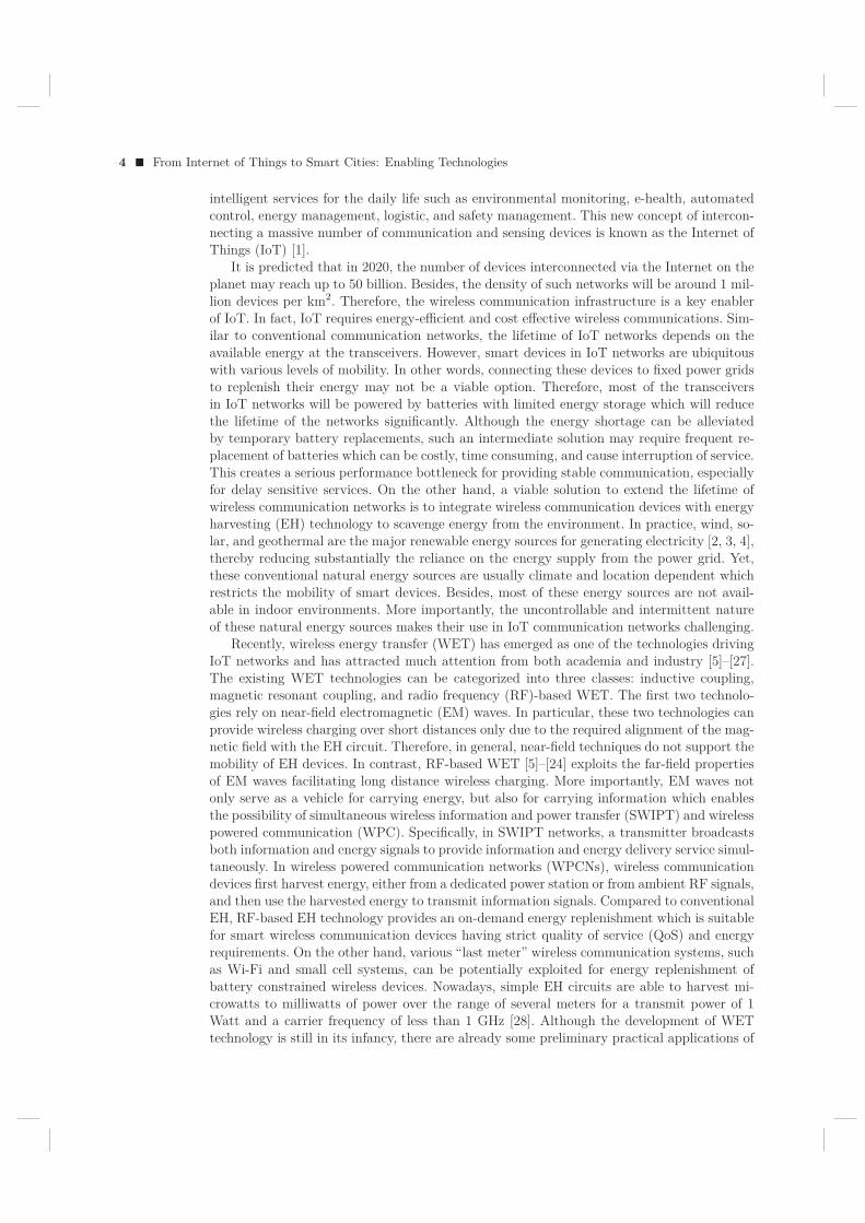
Figure 1.1 Simple receiver structures for wireless information and power transfer; (a) Timeswitching receiver; (b) Power splitting receiver.
information decoding process and EH process have to be separated. A viable solution is tosplit the received RF power into two distinct parts, one for EH and one for informationdecoding. In the following, we discuss two commonly adopted techniques to achieve thissignal splitting.
Time Switching (TS) Receiver:With TS receivers, each transmission block is divided into two orthogonal time slots, one
for transferring wireless power and the other one for transmitting information, cf. Figure1.1a. The co-located energy harvester and information receiver switch between harvestingenergy and decoding in two time slots [17]. In practice, by taking into account the channelstatistics and QoSs for power transfer, the time durations for wireless information transferand energy transfer can be optimized to achieve different system design objectives. Althoughthe TS receiver structure allows for a simple hardware implementation, it requires accuratetime synchronization and information/energy scheduling, especially in multi-user systems.
Power Splitting (PS) Receiver:A power splitting (PS) receiver splits the signal received at the antenna into two streams
at different power levels using a PS unit, cf. Figure 1.1b. In particular, one stream is sent tothe RF energy harvester for EH, and the other one is converted to baseband for informationdecoding [17, 19]. The PS process incurs a higher receiver complexity compared to the TSprocess. Besides, optimization of the ratio of the two power streams is needed in order toachieve a balance between the performances of information decoding and EH. Furthermore,additional noise may be introduced due to the adopted PS process [14]. Nevertheless, thisreceiver structure achieves SWIPT, as the signal received in one time slot is exploited forboth information decoding and power transfer. Therefore, it is more suitable than the TSreceiver for applications with critical information/energy or delay constraints [6].
In the sequel, we study the resource allocation algorithm design for two practical wirelessinformation and power transfer networks based on the TS receiver structure, due to itssimpler hardware implementation. Since the unit of “Joule-per-second” is used for energyconsumption in this chapter, the terms “power” and “energy” are interchangeable.
1.3 SWIPT COMMUNICATION NETWORKS
In this section, we outline the adopted system model for the considered SWIPT systems.
Resource Allocation for Wireless Communication Networks with RF Energy Harvesting � 7
�������� �������������������������
� ����������������
�������������������������!
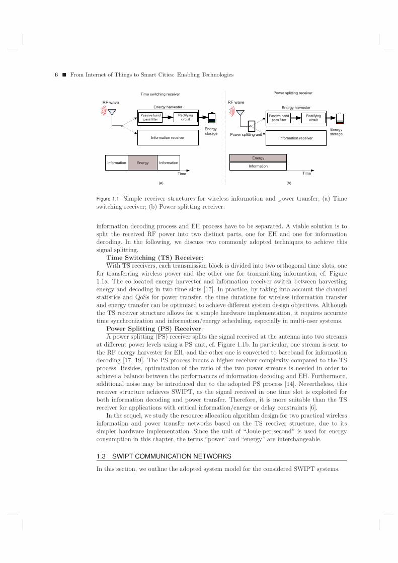
Figure 1.2 A simple SWIPT system model with one information receiver and J = 2 EHreceivers (ERs), e.g. wireless sensors. The ERs harvest energy from the received RF signalsto extend their lifetimes.
1.3.1 Channel Model
A frequency flat fading communication channel is considered. The SWIPT system comprisesa transmitter, an information receiver (IR), and J EH receivers (ER)1, cf. Figure 1.2. Thetransmitter is equipped with NT ≥ 1 antennas and serves both the IR and the ERs simul-taneously in the same frequency band. We assume that the IR is a single-antenna device forassuring low hardware complexity. Each ER is equipped with NR ≥ 1 receive antennas tofacilitate wireless EH. The received signals at the IR and ER j ∈ {1, . . . , J} are given by
y = hHws + wE + n, and (1.1)yERj = GH
j ws + wE + nERj , ∀j ∈ {1, . . . , J}, (1.2)
respectively, where s ∈ C and w ∈ CNT×1 are the data symbol and the information beam-
forming vector, respectively. Without loss of generality, we assume that E{|s|2} = 1. Thechannel vector between the transmitter and the IR is denoted by h ∈ C
NT×1 and the channelmatrix between the transmitter and ER j is denoted by Gj ∈ C
NT×NR . n ∼ CN (0, σ2s ) and
nERj ∼ CN (0, σ2s INR) are the additive white Gaussian noises (AWGN) at the IR and ER j,
respectively, where σ2s denotes the noise power at the receiver. wE ∈ C
NT×1 is a Gaussianpseudo-random sequence generated by the transmitter to facilitate efficient wireless powertransfer. In particular, wE is modelled as a complex Gaussian random vector with
wE ∼ CN (0, WE), (1.3)
where WE ∈ HNT , WE � 0, denotes the covariance matrix of the pseudo-random energy
signal.
1.3.2 Non-linear Energy Harvesting Model
In this section, we discuss two mathematical models used in the literature to capture thecharacteristic of practical RF EH circuits. To this end, we first study a basic approach forextracting electrical energy from the received RF signals. In practice, after the transmittedRF signal is received at the antenna(s) of an ER, a passive bandpass filter is employed beforethe received RF signal is passed on to a rectifying circuit, cf. Figure 1.1. In fact, the rectifyingcircuit is the core element of RF EH circuits. In particular, it is a passive electronic circuit
1The considered system can be treated as having J + 1 TS receivers where one of the receivers is in theIR mode and the remaining J receivers are in the ER mode.
8 � From Internet of Things to Smart Cities: Enabling Technologies
comprising diodes, resistors, and capacitors that converts the incoming RF power to directcurrent (DC) power. Then, the converted power can be stored in the energy storage unit ofthe receiver.
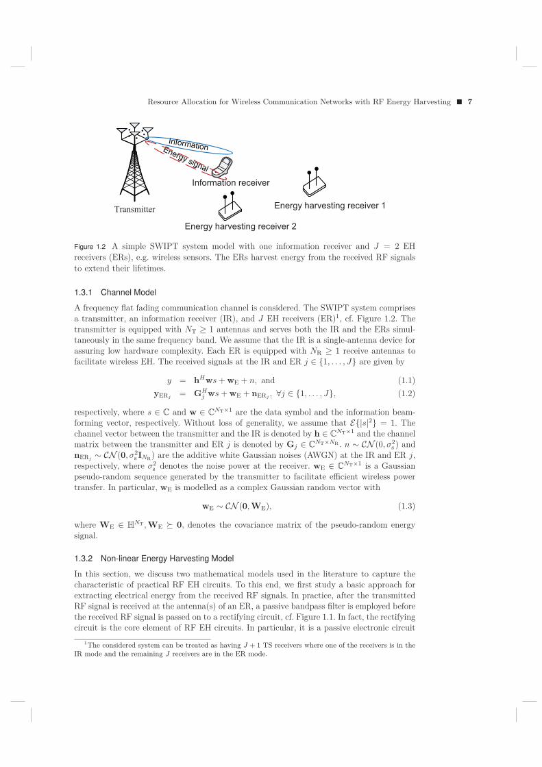
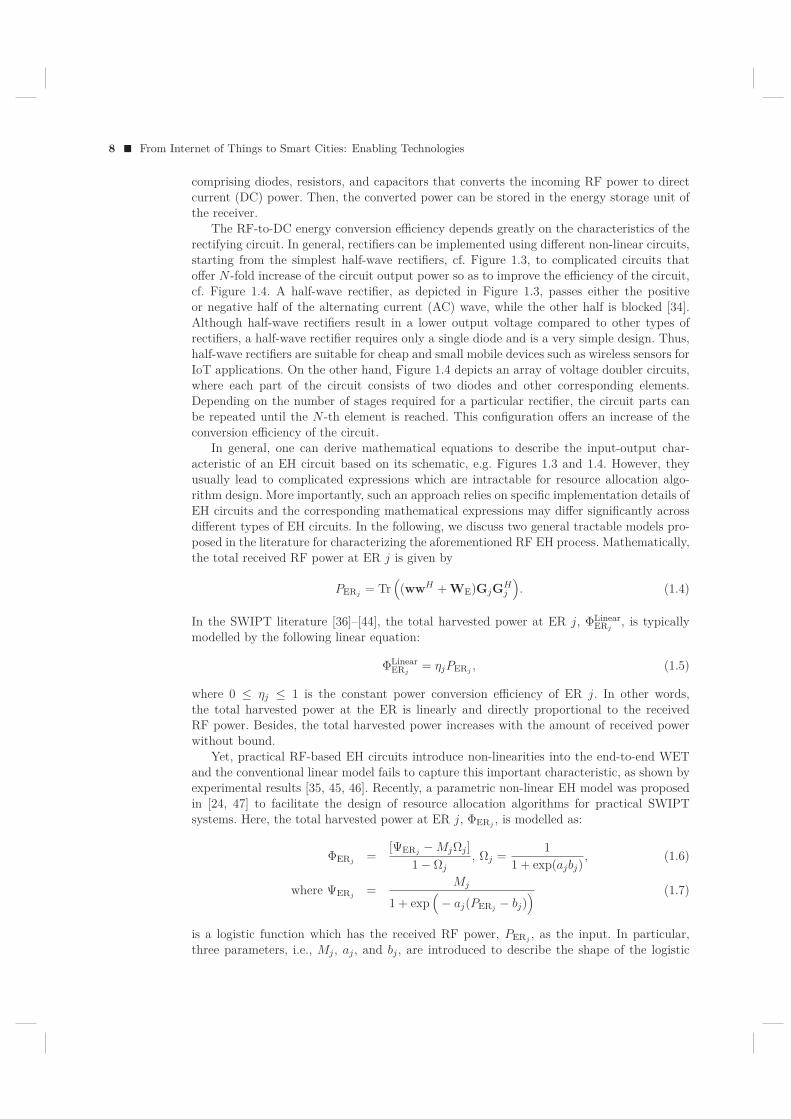
The RF-to-DC energy conversion efficiency depends greatly on the characteristics of therectifying circuit. In general, rectifiers can be implemented using different non-linear circuits,starting from the simplest half-wave rectifiers, cf. Figure 1.3, to complicated circuits thatoffer N -fold increase of the circuit output power so as to improve the efficiency of the circuit,cf. Figure 1.4. A half-wave rectifier, as depicted in Figure 1.3, passes either the positiveor negative half of the alternating current (AC) wave, while the other half is blocked [34].Although half-wave rectifiers result in a lower output voltage compared to other types ofrectifiers, a half-wave rectifier requires only a single diode and is a very simple design. Thus,half-wave rectifiers are suitable for cheap and small mobile devices such as wireless sensors forIoT applications. On the other hand, Figure 1.4 depicts an array of voltage doubler circuits,where each part of the circuit consists of two diodes and other corresponding elements.Depending on the number of stages required for a particular rectifier, the circuit parts canbe repeated until the N -th element is reached. This configuration offers an increase of theconversion efficiency of the circuit.
In general, one can derive mathematical equations to describe the input-output char-acteristic of an EH circuit based on its schematic, e.g. Figures 1.3 and 1.4. However, theyusually lead to complicated expressions which are intractable for resource allocation algo-rithm design. More importantly, such an approach relies on specific implementation details ofEH circuits and the corresponding mathematical expressions may differ significantly acrossdifferent types of EH circuits. In the following, we discuss two general tractable models pro-posed in the literature for characterizing the aforementioned RF EH process. Mathematically,the total received RF power at ER j is given by
PERj = Tr((wwH + WE)GjGH
j
). (1.4)
In the SWIPT literature [36]–[44], the total harvested power at ER j, ΦLinearERj
, is typicallymodelled by the following linear equation:
ΦLinearERj
= ηjPERj , (1.5)
where 0 ≤ ηj ≤ 1 is the constant power conversion efficiency of ER j. In other words,the total harvested power at the ER is linearly and directly proportional to the receivedRF power. Besides, the total harvested power increases with the amount of received powerwithout bound.
Yet, practical RF-based EH circuits introduce non-linearities into the end-to-end WETand the conventional linear model fails to capture this important characteristic, as shown byexperimental results [35, 45, 46]. Recently, a parametric non-linear EH model was proposedin [24, 47] to facilitate the design of resource allocation algorithms for practical SWIPTsystems. Here, the total harvested power at ER j, ΦERj , is modelled as:
ΦERj =[ΨERj −MjΩj ]
1− Ωj, Ωj = 1
1 + exp(ajbj), (1.6)
where ΨERj = Mj
1 + exp(− aj(PERj − bj)
) (1.7)
is a logistic function which has the received RF power, PERj , as the input. In particular,three parameters, i.e., Mj , aj , and bj , are introduced to describe the shape of the logistic
Resource Allocation for Wireless Communication Networks with RF Energy Harvesting � 9
��
�
����� ����� ���
�
�
Figure 1.3 A schematic of a half-wave rectifier [35] where Cload, Rload, D1, and Vout denote aload capacitance, load resistance, diode, and the output voltage, respectively.
��
����
���
�
����� ����� ���
�
��� �
�
�� �
��
�� �
Figure 1.4 A schematic of a Dickson charge pump [35] with N stages, where Di, and Ci, i ∈{1, . . . , N}, denote the diode and the capacitor in the i-th stage.
function which depends on various physical properties of the RF EH circuit. Specifically, Mj
is a positive constant denoting the maximum harvestable power at ER j, when the EH circuitis saturated due to an exceedingly large input power. Parameters aj and bj are constantswhich capture the joint effects of resistance, capacitance, and circuit sensitivity. Specifically,aj denotes the non-linear charging rate with respect to the input power and bj is related tothe minimum turn-on voltage of the EH circuit.
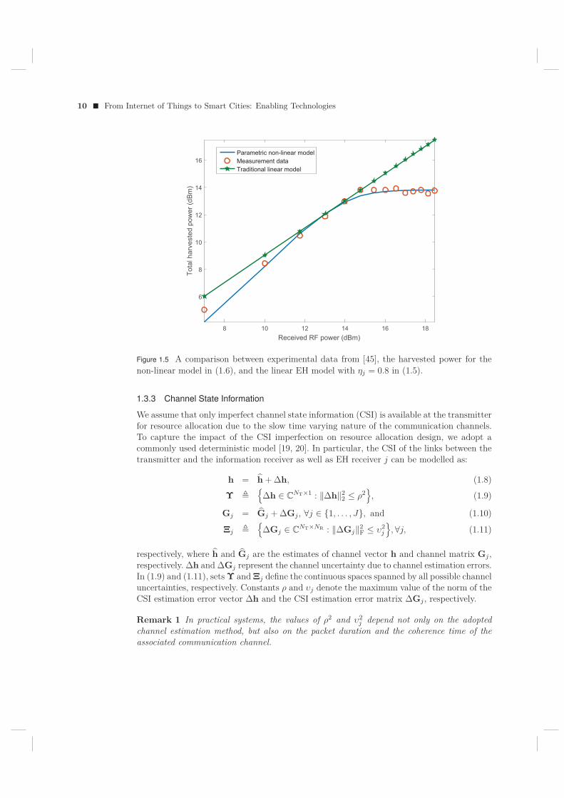
In practice, for a given EH hardware circuit, the values of parameters aj , bj , and Mj ofthe proposed model in (1.6) can be estimated by using a standard curve fitting algorithm.In Figure 1.5, we show an example for the curve fitting for the non-linear EH model in (1.6)with parameters M = 0.024, b = 0.014, and a = 150. As can be observed, the parametricnon-linear model matches the experimental result provided in [45] closely for the RF powerharvested by a practical EH circuit. For comparison, Figure 1.5 also illustrates the totalharvested power predicted by the linear model in (1.5). It can be seen that the conventionallinear RF energy harvesting model fails to capture the non-linear characteristics of practicalEH circuits, especially in high and low received RF power regimes.
10 � From Internet of Things to Smart Cities: Enabling Technologies
8 10 12 14 16 18Received RF power (dBm)
6
8
10
12
14
16
Tota
l har
vest
ed p
ower
(dBm
)
Parametric non-linear modelMeasurement dataTraditional linear model
Figure 1.5 A comparison between experimental data from [45], the harvested power for thenon-linear model in (1.6), and the linear EH model with ηj = 0.8 in (1.5).
1.3.3 Channel State Information
We assume that only imperfect channel state information (CSI) is available at the transmitterfor resource allocation due to the slow time varying nature of the communication channels.To capture the impact of the CSI imperfection on resource allocation design, we adopt acommonly used deterministic model [19, 20]. In particular, the CSI of the links between thetransmitter and the information receiver as well as EH receiver j can be modelled as:
h = h + Δh, (1.8)
Υ �{
Δh ∈ CNT×1 : ‖Δh‖2
2 ≤ ρ2}
, (1.9)
Gj = Gj + ΔGj , ∀j ∈ {1, . . . , J}, and (1.10)
Ξj �{
ΔGj ∈ CNT×NR : ‖ΔGj‖2
F ≤ υ2j
}, ∀j, (1.11)
respectively, where h and Gj are the estimates of channel vector h and channel matrix Gj ,respectively. Δh and ΔGj represent the channel uncertainty due to channel estimation errors.In (1.9) and (1.11), sets Υ and Ξj define the continuous spaces spanned by all possible channeluncertainties, respectively. Constants ρ and υj denote the maximum value of the norm of theCSI estimation error vector Δh and the CSI estimation error matrix ΔGj , respectively.
Remark 1 In practical systems, the values of ρ2 and υ2j depend not only on the adopted
channel estimation method, but also on the packet duration and the coherence time of theassociated communication channel.
Resource Allocation for Wireless Communication Networks with RF Energy Harvesting � 11
1.3.4 Achievable System Data Rate
The energy signal wE is a Gaussian pseudo-random sequence which is known to all thetransceivers. Hence, interference cancellation can be performed at the IR to facilitate in-formation decoding. As a result, given perfect CSI at the receiver for coherent informationdecoding, the achievable rate (bit/s/Hz) between the transmitter and the IR is given by
R = log2
(1 + |hHw|2
σ2s
), (1.12)
where the interference caused by the energy signal, i.e., Tr(hHWEh), has been removed.
1.3.5 Problem Formulation and Solution
In the considered SWIPT system, we aim to maximize the total achievable data rate of thesystem while guaranteeing a minimum total harvested power at multiple ERs. The resourceallocation algorithm design is formulated as the following optimization problem:
Problem 1 Robust Resource Allocation for SWIPT:
maximizew,WE∈H
NTmin
Δh∈Υlog2
(1 + |hHw|2
σ2s
)(1.13)
subject to C1 : ‖w‖22 + Tr(WE) ≤ Pmax,
C2 : minΔGj∈Ξj
ΦERj ≥ Preqj,∀j ∈ {1, . . . , J}.
The objective function in (1.13) takes into account the CSI uncertainty set Υ to providerobustness against CSI imperfection. Constants Pmax and Preqj
in constraints C1 and C2 arethe maximum transmit power from the power station and the required minimum harvestedpower at ER j, respectively. It can be observed that there are infinitely many possibilitiesin both the objective function and constraint C2, due to the CSI uncertainties. In order todesign a computationally efficient resource allocation algorithm, we first define W = wwH
and transform the considered problem into the following equivalent rank-constrained semi-definite program (SDP):
Problem 2 Rank-constrained Robust Resource Allocation for SWIPT:
maximizeW,WE∈H
NT , τ,βτ (1.14)
subject to C1 : Tr(W + WE) ≤ Pmax,
C2 : Mj ≥ Θj
(1 + exp
(− aj(βj − bj)
)), ∀j ∈ {1, . . . , J},
C3 : minΔh∈Υ
Tr(WH) ≥ τ,
C4 : minΔGj∈Ξj
Tr((W + WE)GjGHj ) ≥ βj , ∀j ∈ {1, . . . , J},
C5 : Rank(W) ≤ 1,
C6 : W � 0,
C7 : WE � 0,
12 � From Internet of Things to Smart Cities: Enabling Technologies
where
Θj = Preqj(1− Ωj) + MjΩj and (1.15)
H = hhH . (1.16)
β = {β1, . . . , βj , . . . , βJ} and τ are auxiliary optimization variables. We note that W � 0,W ∈ H
NT , and Rank(W) = 1 in (1.14) are imposed to guarantee that W = wwH afteroptimization. Now, the transformed problem in (1.14) involves infinitely many constraintsonly in C3 and C4. Besides, the rank constraint in C5 is non-convex. To further facilitatethe solution, we first transform constraints C3 and C4 into linear matrix inequalities (LMIs)using the following lemma:
Lemma 1 (S-Procedure [48]) Let a function fm(x), m ∈ {1, 2}, x ∈ CN×1, be defined as
fm(x) = xHAmx + 2Re{bHmx}+ cm, (1.17)
where Am ∈ HN , bm ∈ C
N×1, and cm ∈ R. Then, the implication f1(x) ≤ 0 ⇒ f2(x) ≤ 0holds if and only if there exists a δ ≥ 0 such that
δ
[A1 b1bH
1 c1
]−
[A2 b2bH
2 c2
]� 0, (1.18)
provided that there exists a point x such that fm(x) < 0.
Exploiting Lemma 1, the original constraint C3 holds if and only if there exists a δ ≥ 0,such that the following LMI constraint holds:
C3: SC3
(W, δ, τ
)=
[δINT 0
0 −δρ2 − τ
]+UH
h WUh � 0, (1.19)
where Uh =[INT h
]. Similarly, constraint C4 can be equivalently written as
C4: SC4j
(W, WE,ν,β
)(1.20)
=[νjINTNR 0
0 −βj − νjυ2j
]+ UH
gj(W + WE)Ugj
� 0,∀j,
for ν = {ν1, . . . , νj , . . . , νJ}, νj ≥ 0, W = INR ⊗W, WE = INR ⊗WE, Ugj= [INTNR gj ],
and gj = vec(Gj) . Then, the considered optimization problem can be rewritten as
Problem 3 Rank-constrained SDP for SWIPT:
maximizeW,WE∈H
NT , τ,ν, δ,βτ (1.21)
subject to C1 : Tr(W + WE) ≤ Pmax,
C2 : Mj ≥ Θj
(1 + exp
(− aj(βj − bj)
)), ∀j ∈ {1, . . . , J},
C3 : SC3
(W, δ, τ
)� 0,
C4 : SC4j
(W, WE,ν,β
)� 0, , ∀j ∈ {1, . . . , J},
C5 : Rank(W) ≤ 1,
C6 : W � 0,
C7 : WE � 0,
Resource Allocation for Wireless Communication Networks with RF Energy Harvesting � 13
where δ and ν are the non-negative auxiliary optimization variables introduced in Lemma 1for handling constraints C3 and C4, respectively. We note that constraints C3 and C4 involveonly a finite number of LMI constraints which facilitates the resource allocation algorithmdesign. However, the rank constraint in C5 is still an obstacle in solving the consideredoptimization problem due to its combinatorial nature. As a result, we adopt SDP relaxationby removing constraint C5 from the problem formulation which yields:
Problem 4 SDP relaxation of (1.21)
maximizeW,WE∈H
NT , τ,ν, δ,βτ (1.22)
subject to C1 : Tr(W + WE) ≤ Pmax,
C2 : Mj ≥ Θj
(1 + exp
(− aj(βj − bj)
)), ∀j ∈ {1, . . . , J},
C3 : SC3
(W, δ, τ
)� 0,
C4 : SC4j
(W, WE,ν,β
)� 0, , ∀j ∈ {1, . . . , J},
C5 : �������Rank(W) ≤ 1 .
C6 : W � 0,
C7 : WE � 0 .
The rank relaxed problem is a convex optimization problem and can be solved efficientlyby standard numerical solvers such as CVX [49]. Yet, the constraint relaxation may not betight when Rank(W) > 1 and in that case the result of the relaxed problem serves as aperformance upper bound for the original problem. Therefore, we study the tightness of theadopted SDP relaxation in the following theorem.
Theorem 1 Assuming the considered problem is feasible for Pmax > 0, a rank-one solu-tion of (1.22) can always be constructed.
Proof: Please refer to Appendix 1.6.1.In other words, (1.21) can be solved optimally. In particular, information beamforming
is optimal for the maximization of achievable rate, despite the imperfection of the CSI andnon-linearity of the RF EH circuits.
1.3.6 Numerical Example
In this section, we evaluate the IoT system performance of the proposed optimal resourceallocation algorithm via simulations. We summarize the important simulation parameters inTable 1.1. We assume that the IR and the J ERs are located at 100 meters and 5 metersfrom the transmitter, respectively. In particular, the IR is an IoT device connecting to thetransmitter for information transfer while the J ERs are idle IoT receivers requesting wirelessenergy to extend their lifetimes. Unless further specified, we adopt the normalized maximumchannel estimation errors of ER j and the IR as σ2
estG= 1% ≥ υ2
j
‖Gj‖2F
,∀j, and σ2esth
= 1% ≥
14 � From Internet of Things to Smart Cities: Enabling Technologies
Table 1.1 Simulation Parameters.
Carrier center frequency 915 MHzBandwidth 200 kHzTransceiver antenna gain 10 dBiNumber of receive antennas NR 2Noise power σ2 −95 dBmMaximum transmit power Pmax 36 dBmTransmitter-to-ER fading distribution Rician with Rician factor 3 dBTransmitter-to-IR fading distribution Rayleigh
8 9 10 11 12 13
6.5
7
7.5
8
8.5
9
9.5
Average harvested power (dBm)
Aver
age
achi
evab
le d
ata
rate
(bit/
s/H
z)
Performance gain
Performance gain
NT = 8, NR = 5
NT = 8, NR = 3
NT = 6, NR = 5
NT = 6, NR = 3
Figure 1.6 Average achievable data rate (bit/s/Hz) versus the average harvested power (dBm)for different numbers of antennas.
ρ2
‖h‖22. For the non-linear EH circuits, we set Mj = 24 mW which corresponds to the maximum
harvested power per wireless powered device. Besides, we adopt aj = 150 and bj = 0.014.We solve the optimization problem in (1.22) and obtain the average system performance byaveraging over different channel realizations.
In Figure 1.6, we show the average achievable rate of the system versus the average totalharvested energy in a downlink system for the optimal beamforming scheme. In particular, atransmitter equipped with NT antennas serves a single-antenna IR and J = 1 ER. As can beobserved, there is a non-trivial trade-off between the achievable system data rate and the totalharvested energy. In other words, system data rate maximization and total harvested energymaximization are two conflicting system design objectives. Besides, for the optimal resourceallocation, the trade-off region of the system achievable rate and the harvested energy isenlarged significantly with NT and NR. This is due to the fact that the extra degrees offreedom offered by multiple transmit antennas help the transmitter to focus the energy ofthe information signal and thus improve the beamforming efficiency. On the other hand,increasing the number of receive antennas NR can significantly improve the total harvested
Resource Allocation for Wireless Communication Networks with RF Energy Harvesting � 15
1 2 3 4 5 6Number of ERs
7
7.5
8
8.5
9
9.5
Aver
age
achi
evab
le d
ata
rate
(bit/
s/H
z)
Preqj
= 5 dBm, σest2 = 1 %
Preqj
= 8 dBm, σest2 = 1 %
Preqj
= 5 dBm, σest2 = 5 %
Preqj
= 8 dBm, σest2 = 5 %
Figure 1.7 Average achievable data rate (bit/s/Hz) versus the number of ERs for NT = 8.
energy at the ER. In fact, the extra receiver antennas act as additional energy collectorswhich enables a more efficient energy transfer. Furthermore, it is verified by simulation thatRank(W) = 1 can be obtained/construsted for all the considered channel realizations whichconfirms the correctness of Theorem 1.
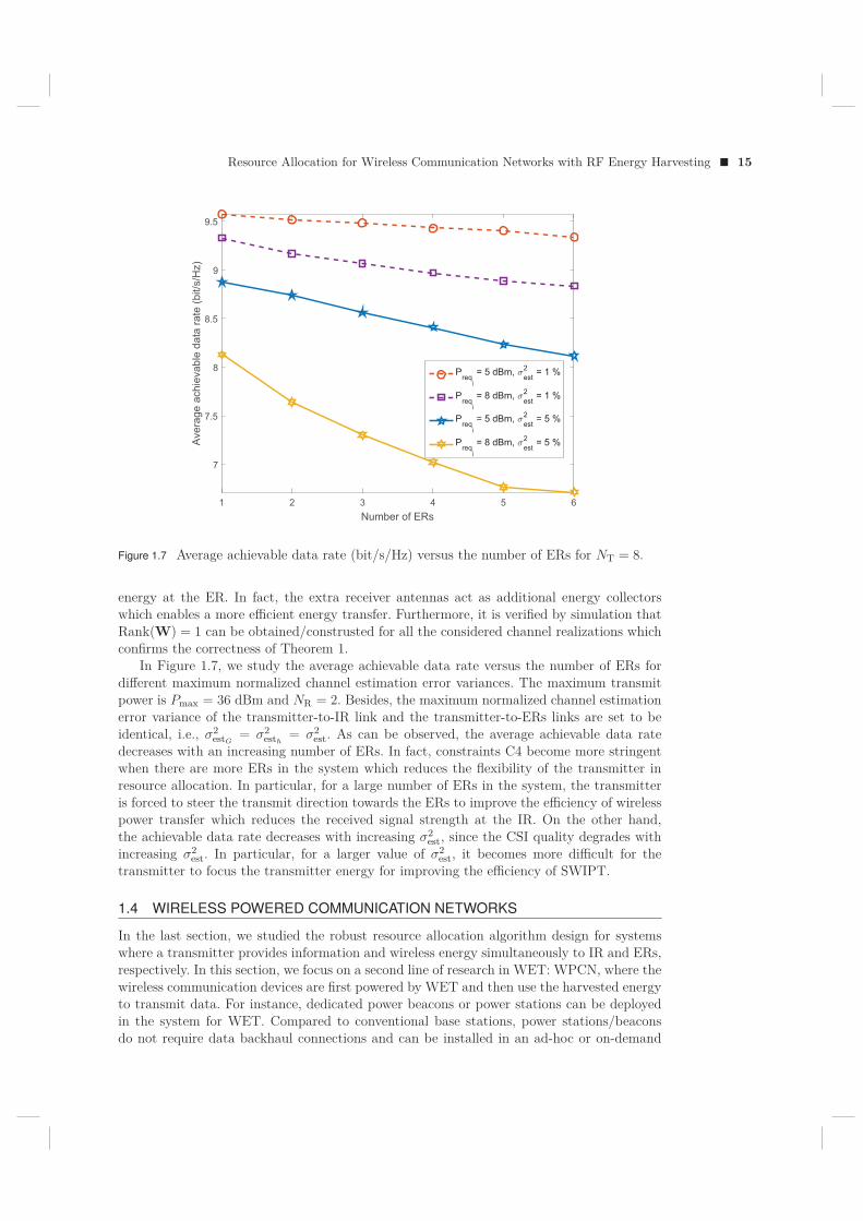
In Figure 1.7, we study the average achievable data rate versus the number of ERs fordifferent maximum normalized channel estimation error variances. The maximum transmitpower is Pmax = 36 dBm and NR = 2. Besides, the maximum normalized channel estimationerror variance of the transmitter-to-IR link and the transmitter-to-ERs links are set to beidentical, i.e., σ2
estG= σ2
esth= σ2
est. As can be observed, the average achievable data ratedecreases with an increasing number of ERs. In fact, constraints C4 become more stringentwhen there are more ERs in the system which reduces the flexibility of the transmitter inresource allocation. In particular, for a large number of ERs in the system, the transmitteris forced to steer the transmit direction towards the ERs to improve the efficiency of wirelesspower transfer which reduces the received signal strength at the IR. On the other hand,the achievable data rate decreases with increasing σ2
est, since the CSI quality degrades withincreasing σ2
est. In particular, for a larger value of σ2est, it becomes more difficult for the
transmitter to focus the transmitter energy for improving the efficiency of SWIPT.
1.4 WIRELESS POWERED COMMUNICATION NETWORKS
In the last section, we studied the robust resource allocation algorithm design for systemswhere a transmitter provides information and wireless energy simultaneously to IR and ERs,respectively. In this section, we focus on a second line of research in WET: WPCN, where thewireless communication devices are first powered by WET and then use the harvested energyto transmit data. For instance, dedicated power beacons or power stations can be deployedin the system for WET. Compared to conventional base stations, power stations/beaconsdo not require data backhaul connections and can be installed in an ad-hoc or on-demand
16 � From Internet of Things to Smart Cities: Enabling Technologies
manner. This kind of system setup has various IoT applications for energy-limited wirelesscommunication sensors which need to first harvest enough energy from the environmentbefore sending information to an information receiver. In the following, we discuss a resourceallocation design to improve the system performance of such a WPCN.
1.4.1 Channel Model
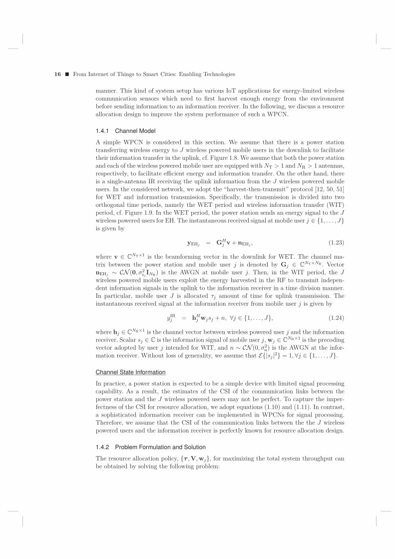
A simple WPCN is considered in this section. We assume that there is a power stationtransferring wireless energy to J wireless powered mobile users in the downlink to facilitatetheir information transfer in the uplink, cf. Figure 1.8. We assume that both the power stationand each of the wireless powered mobile user are equipped with NT > 1 and NR > 1 antennas,respectively, to facilitate efficient energy and information transfer. On the other hand, thereis a single-antenna IR receiving the uplink information from the J wireless powered mobileusers. In the considered network, we adopt the “harvest-then-transmit” protocol [12, 50, 51]for WET and information transmission. Specifically, the transmission is divided into twoorthogonal time periods, namely the WET period and wireless information transfer (WIT)period, cf. Figure 1.9. In the WET period, the power station sends an energy signal to the Jwireless powered users for EH. The instantaneous received signal at mobile user j ∈ {1, . . . , J}is given by
yEHj = GHj v + nEHj , (1.23)
where v ∈ CNT×1 is the beamforming vector in the downlink for WET. The channel ma-
trix between the power station and mobile user j is denoted by Gj ∈ CNT×NR . Vector
nEHj ∼ CN (0, σ2sj
INR) is the AWGN at mobile user j. Then, in the WIT period, the Jwireless powered mobile users exploit the energy harvested in the RF to transmit indepen-dent information signals in the uplink to the information receiver in a time division manner.In particular, mobile user J is allocated τj amount of time for uplink transmission. Theinstantaneous received signal at the information receiver from mobile user j is given by
yIRj = hH
j wjsj + n, ∀j ∈ {1, . . . , J}, (1.24)
where hj ∈ CNR×1 is the channel vector between wireless powered user j and the information
receiver. Scalar sj ∈ C is the information signal of mobile user j, wj ∈ CNR×1 is the precoding
vector adopted by user j intended for WIT, and n ∼ CN (0, σ2n) is the AWGN at the infor-
mation receiver. Without loss of generality, we assume that E{|sj |2} = 1,∀j ∈ {1, . . . , J}.
Channel State Information
In practice, a power station is expected to be a simple device with limited signal processingcapability. As a result, the estimates of the CSI of the communication links between thepower station and the J wireless powered users may not be perfect. To capture the imper-fectness of the CSI for resource allocation, we adopt equations (1.10) and (1.11). In contrast,a sophisticated information receiver can be implemented in WPCNs for signal processing.Therefore, we assume that the CSI of the communication links between the the J wirelesspowered users and the information receiver is perfectly known for resource allocation design.
1.4.2 Problem Formulation and Solution
The resource allocation policy, {τ , V, wj}, for maximizing the total system throughput canbe obtained by solving the following problem:
Resource Allocation for Wireless Communication Networks with RF Energy Harvesting � 17
"���������������������
"���������������������!
������������
��������������
� ����������������
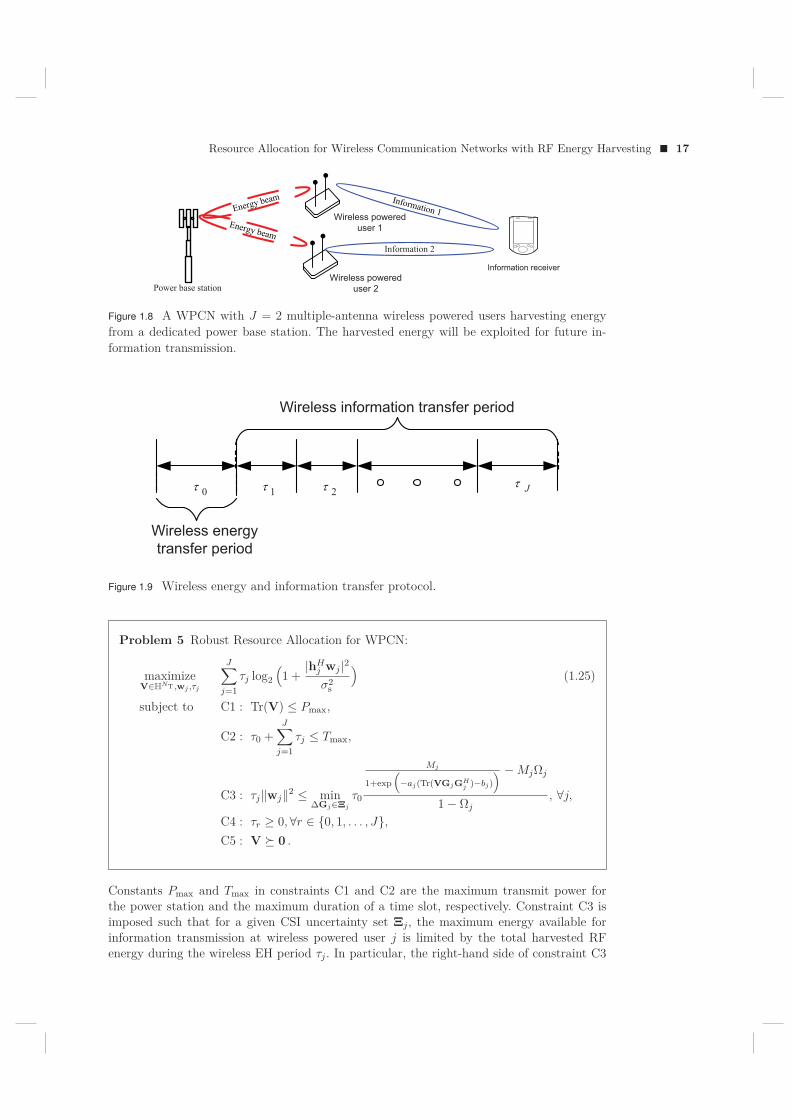
Figure 1.8 A WPCN with J = 2 multiple-antenna wireless powered users harvesting energyfrom a dedicated power base station. The harvested energy will be exploited for future in-formation transmission.
"������������������ ����������
τ �τ �τ �τ
"��������� ������������ ����������
Figure 1.9 Wireless energy and information transfer protocol.
Problem 5 Robust Resource Allocation for WPCN:
maximizeV∈H
NT ,wj ,τj
J∑j=1
τj log2
(1 +
|hHj wj |2σ2
s
)(1.25)
subject to C1 : Tr(V) ≤ Pmax,
C2 : τ0 +J∑
j=1τj ≤ Tmax,
C3 : τj‖wj‖2 ≤ minΔGj∈Ξj
τ0
Mj
1+exp(
−aj(Tr(VGjGHj )−bj)
) −MjΩj
1− Ωj, ∀j,
C4 : τr ≥ 0, ∀r ∈ {0, 1, . . . , J},C5 : V � 0 .
Constants Pmax and Tmax in constraints C1 and C2 are the maximum transmit power forthe power station and the maximum duration of a time slot, respectively. Constraint C3 isimposed such that for a given CSI uncertainty set Ξj , the maximum energy available forinformation transmission at wireless powered user j is limited by the total harvested RFenergy during the wireless EH period τj . In particular, the right-hand side of constraint C3
18 � From Internet of Things to Smart Cities: Enabling Technologies
denotes the total harvested power at ER j if a practical non-linear RF EH circuit is assumed2.C4 is the non-negativity constraint for information scheduling variable τj . Constraint C5 andV ∈ H
NT constrain matrix V to be a positive semi-definite Hermitian matrix.The optimization problem in (1.25) is a non-convex optimization problem which involves
infinitely many constraints in C3. Besides, inequality constraint C3 involves the couplingof optimization variables τj and wj . Furthermore, the right-hand side of constraint C3 is aquasi-concave function. In general, there is no systematic approach for solving non-convexoptimization problems. In order to obtain a computationally efficient resource allocationalgorithm design, we introduce several transformations of the optimization problem. First,to handle the quasi-concavity of constraint C3, we solve the optimization problem for a fixedconstant τ0 and obtain an optimal solution for one instant of the optimization problem. Then,we repeat the procedure for all possible values of τ0 and record the corresponding achievedsystem objective values. At the end, we select that τ0 as the optimal time allocation forWET from all the trials which provides the maximum system objective value. Therefore, inthe sequel, we assume that τ0 is given by its optimal value for the design of the resourceallocation algorithm.
Next, we introduce a change of variable to decouple the optimization variables in con-straint C3. Specifically, we define a new optimization variable wj =
√τ jwj and rewrite the
optimization problem as
Problem 6 Transformed Problem for WPCN:
maximizeV∈H
NT ,wj∈HNU ,τj ,βj
J∑j=1
τj log2
(1 +
|hHj wj |2τjσ2
s
)(1.26)
subject to C1 : Tr(V) ≤ Pmax,
C2 : τ0 +J∑
j=1τj ≤ Tmax,
C3 : ‖wj‖2 ≤ τ0
Mj
1+exp(
−aj(βj−bj)) −MjΩj
1− Ωj, ∀j,
C4 : τr ≥ 0,∀r ∈ {0, 1, . . . , J},C5 : V � 0,
C6 : minΔGj∈Ξj
Tr(VGjGHj ) ≥ βj ,∀j ∈ {1, . . . , J}.
To handle the infinitely many constraints in C6, we can apply Lemma 1 for (1.26). Inparticular, constraint C6 can be equivalently written as
C6: SC6j
(V,μ,β
)(1.27)
=[νjINTNR 0
0 −βj − νjυ2j
]+ UH
gjVUgj
� 0,∀j,
for ν = {ν1, . . . , νj , . . . , νJ}, νj ≥ 0, V = INR ⊗V, Ugj= [INTNR gj ], and gj = vec(Gj).
2Here, we assume that the circuit power consumption of each wireless powered user is negligibly smallcompared to the transmit power consumption and thus is not taken into account.
Resource Allocation for Wireless Communication Networks with RF Energy Harvesting � 19
Table 1.2 Simulation Parameters.
Carrier center frequency 915 MHzBandwidth 200 kHzTransceiver antenna gain 10 dBiNoise power (including quantization noise) σ2 −47 dBmPower station-to-wireless powered user distance 5 metersPower station-to-wireless powered user fading distribution Rician with Rician factor 3 dBWireless powered user-to-IR fading distribution RayleighMaximum duration of a communication slot, Tmax 1 unit
Problem 7 Transformed Problem for WPCN:
maximizeV∈H
NT ,wj∈HNU ,τj ,βj ,μj
J∑j=1
τj log2
(1 +
|hHj wj |2τjσ2
s
)(1.28)
subject to C1− C5,
C6: SC6j
(V,μ,β
)� 0, ∀j ∈ {1, . . . , J}.
The above transformed problem is jointly concave with respect to the optimization vari-ables and can be solved efficiently via standard numerical solvers for convex programs.
1.4.3 Numerical Example
In this section, we evaluate the IoT system performance of the proposed resource allocationalgorithm via simulations. We summarize the relevant simulation parameters in Table 1.2.We assume that a dedicated power station is deployed for wireless charging of IoT devices.There are J = 4 ERs in the IoT network requiring energy for WIT. For the non-linear EHcircuits, we set Mj = 24 mW which corresponds to the maximum harvested power per ER.Besides, we adopt aj = 150 and bj = 0.014. To obtain the average system performance, wesolve the optimization problem in (1.28) for each channel realization and average the resultover different channel realizations.
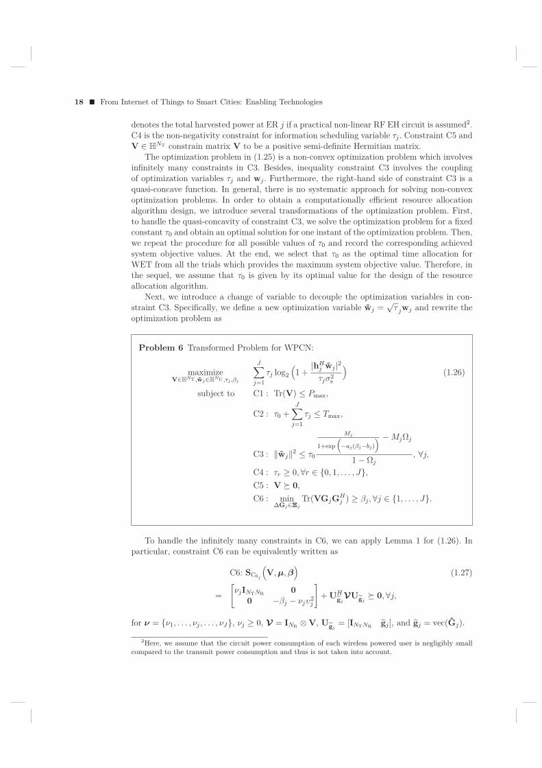
In Figure 1.10, we study the average total system throughput versus the maximum trans-mit power from the power station, Pmax, for different numbers of antennas equipped at thepower station, NT, and at the wireless powered users, NR. We set the normalized maximumchannel estimation errors of wireless powered user j as σ2
estG= 1% ≥ υ2
j
‖Gj‖2F
, ∀j. As can beobserved, the average total system throughput increases with increasing Pmax. Indeed, with ahigher value of Pmax, the wireless powered users are able to harvest more energy for informa-tion transmission. However, there is a diminishing return in performance as Pmax increases inthe high transmit power regime. This is due to the fact that the high transmit power from thepower station causes saturation in practical non-linear EH circuits which limits the availableharvested power for WIT. On the other hand, when the number of antennas equipped at thepower base station increases, a higher system throughput can be achieved by the proposedoptimal scheme. In fact, the extra antennas provide extra spatial degrees of freedom whichfacilitates a more flexible resource allocation, since the power station can steer the energysignal towards the wireless powered users more accurately to improve the efficiency of WET.
20 � From Internet of Things to Smart Cities: Enabling Technologies
28 30 32 34 36 38 40 42Pmax (dBm)
1.8
2
2.2
2.4
2.6
2.8
3
3.2
3.4
3.6
3.8
Aver
age
syts
em th
roug
hput
(bit/
s/H
z)
NT = 6, NR = 5
NT = 5, NR = 6
NT = 8, NR = 5
NT = 5, NR = 8
Figure 1.10 Average system throughput (bit/s/Hz) versus the maximum transmit power atthe power base station (dBm).
27 30 33 36 39 42Pmax (dBm)
0
0.1
0.2
0.3
0.4
0.5
0.6
0.7
0.8
Tim
e al
loca
tion
ratio
WET
WIT
Figure 1.11 Time allocation ratio for WET and WIT versus the maximum transmit power atthe power base station (dBm).
Resource Allocation for Wireless Communication Networks with RF Energy Harvesting � 21
Besides, the system throughput increases rapidly with the number of antennas equipped atthe wireless powered users. In fact, the extra antennas equipped at the wireless powered usersact as additional wireless energy collectors which increase the amount of total harvested en-ergy. Furthermore, the extra antennas at the wireless powered users would also provide extraspatial degrees of freedom which improves the transmit beamforming gain in the WIT phase.
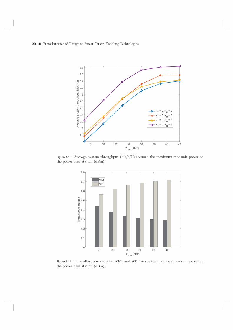
Figure 1.11 shows the time allocation ratio for the proposed algorithm with respect tothe WET and WIT periods for the case of NT = 6 and NR = 5 in Figure 1.10. As canbe observed, WET period for the proposed scheme becomes shorter as the value of Pmaxincreases. In fact, for a higher maximum transmit power from the power station, the wirelesspowered users can harvest the amount of energy required for information transmission in ashorter period of time. In contrast, the WIT period becomes longer for an increasing value ofPmax. This is due to the fact that the achievable throughput of each wireless powered user isan increasing function with respect to the time allocation for information transmission, i.e.,τj , for a fixed amount of total transmit energy. In the extreme case, for a sufficiently largePmax, one can expect that τ0 → 0 since an infinitesimal amount of time is enough to providesufficient energy to fully charge the wireless powered users.
1.5 CONCLUSION
In this chapter, we studied resource allocation algorithms for two RF-based EH wirelesscommunication network architectures, which are of interest for IoT applications. We firstdiscussed a parametric non-linear EH model which facilitates the resource allocation algo-rithm design to enable efficient wireless powered IoT communication networks. The algorithmdesigns were formulated as two non-convex optimization problems for maximizing the sum-throughput in SWIPT and WPCN systems, respectively. The problem formulations tookinto account the imperfectness of the CSI and the non-linearity of the EH circuits in orderto ensure robust resource allocation. The proposed resource allocation design optimizationproblems were optimally solved by advanced signal processing techniques. Numerical resultsshowed the potential gains in harvested power enabled by the proposed optimization and thebenefits in adopting multiple-antenna technology for IoT communication networks.
Acknowledgements
This work was supported in part by the AvH Professorship Program of the Alexander vonHumboldt Foundation and by the Australian Research Council (ARC) Linkage Project LP160100708.
22 � From Internet of Things to Smart Cities: Enabling Technologies
1.6 APPENDIX
1.6.1 Proof of Theorem 1
We provide a method for constructing an optimal rank-one solution for (1.22) whenRank(W) > 1 is obtained from (1.22). For a given optimal τ ∗ from the solution of (1.22),we solve the following auxiliary convex optimization problem [52, 53]:
Auxiliary Convex Optimization Problem
minimizeW,WE∈H
NT , ν, δ,βTr(W) (1.29)
subject to C1, C2, C4, C6, C7,
C3 : SC3
(W, δ, τ ∗
)� 0 .
We note that the optimal resource allocation policy obtained from the above auxiliaryconvex optimization problem is also an optimal resource allocation policy for (1.22), sinceboth problems have the same feasible solution set and τ ∗ is fixed for (1.29).
Now, we aim to show that (1.29) admits a rank-one beamforming matrix. In this context,we first need the Lagrangian of problem (1.29):
L = Tr(W) + λ(Tr(W + WE)− Pmax)− Tr(WY)
−J∑
j=1Tr(SC4j
(W, WE,ν,β
)DC4j
)
− Tr(SC3
(W, δ, τ
)DC3)− Tr(WEZ) + Δ, (1.30)
where λ ≥ 0, DC3 � 0, DC4j� 0, ∀j ∈ {1, . . . , J}, Y � 0, and Z � 0 are the dual variables
for constraints C1, C3, C4, C6, and C7, respectively. Δ is a collection of primal and dualvariables and constants that are not relevant to the proof.
Now, we focus on those Karush-Kuhn-Tucker (KKT) conditions which are needed for theproof.
and d = lNT. The optimal primal and dual variables of the SDP relaxed version are denotedby the corresponding variables with an asterisk superscript.
Subtracting (1.31d) from (1.31c) yields:
Y∗ + UhDC3UHh = Z∗ + INT . (1.32)
Resource Allocation for Wireless Communication Networks with RF Energy Harvesting � 23
Next, we multiply the both sides of (1.31c) by W∗ leading to
W∗UhDC3UHh = W∗(Z∗ + INT). (1.33)
From (1.33), we can deduce that
Rank(W∗) = Rank(W∗UhDC3UHh ) (1.34)
≤ min{Rank(W∗), Rank(UhDC3UHh )}.
Therefore, if Rank(UhDC3UHh ) ≤ 1, then Rank(W∗) ≤ 1. To show Rank(UhDC3UH
h ) ≤1, we pre-multiply and post-multiply (1.31e) by [INT 0] and UH
h , respectively. After somemathematical manipulations, we have the following equality:
(δINT + W∗)UhDC3UHh = δ[0 h]DC3UH
h . (1.35)
Besides, it can be shown that δINT + W∗ 0 and δ > 0 hold for the optimal solution suchthat the dual optimal solution is bounded from above. Therefore, we have
Rank(UhDC3UHh ) = Rank(δ[0 h]DC3UH
h ) ≤ Rank([0 h]) ≤ 1. (1.36)
By combining (1.34) and (1.36), we can conclude that Rank(W∗) ≤ 1. On the other hand,W∗ �= 0 is not optimal for Pmax > 0 and thus Rank(W∗) = 1. �
Bibliography
[1] M. Zorzi, A. Gluhak, S. Lange, and A. Bassi, “From today’s INTRAnet of things to aFuture INTERnet of Things: a Wireless- and Mobility-Related View,” IEEE WirelessCommun., vol. 17, pp. 44–51, Dec. 2010.
[2] D. W. K. Ng, E. S. Lo, and R. Schober, “Energy-Efficient Resource Allocation inOFDMA Systems with Hybrid Energy Harvesting Base Station,” IEEE Trans. WirelessCommun., vol. 12, pp. 3412–3427, Jul. 2013.
[3] M. Zhang and Y. Liu, “Energy Harvesting for Physical-Layer Security in OFDMA Net-works,” IEEE Trans. Inf. Forensics Security, vol. 11, pp. 154–162, Jan. 2016.
[4] I. Ahmed, A. Ikhlef, D. W. K. Ng, and R. Schober, “Power Allocation for an EnergyHarvesting Transmitter with Hybrid Energy Sources,” IEEE Trans. Wireless Commun.,vol. 12, pp. 6255–6267, Dec. 2013.
[5] P. Grover and A. Sahai, “Shannon Meets Tesla: Wireless Information and Power Trans-fer,” in Proc. IEEE Intern. Sympos. on Inf. Theory, Jun. 2010, pp. 2363 –2367.
[6] I. Krikidis, S. Timotheou, S. Nikolaou, G. Zheng, D. W. K. Ng, and R. Schober, “Simul-taneous Wireless Information and Power Transfer in Modern Communication Systems,”IEEE Commun. Mag., vol. 52, no. 11, pp. 104–110, Nov. 2014.
[7] Z. Ding, C. Zhong, D. W. K. Ng, M. Peng, H. A. Suraweera, R. Schober, and H. V. Poor,“Application of Smart Antenna Technologies in Simultaneous Wireless Information andPower Transfer,” IEEE Commun. Mag., vol. 53, no. 4, pp. 86–93, Apr. 2015.
[8] X. Chen, Z. Zhang, H.-H. Chen, and H. Zhang, “Enhancing Wireless Information andPower Transfer by Exploiting Multi-Antenna Techniques,” IEEE Commun. Mag., no. 4,pp. 133–141, Apr. 2015.
[9] X. Chen, D. W. K. Ng, and H.-H. Chen, “Secrecy Wireless Information and PowerTransfer: Challenges and Opportunities,” IEEE Commun. Mag., vol. 23, no. 2, pp. 54–61, Apr. 2016.
[10] X. Chen, J. Chen, and T. Liu, “Secure Transmission in Wireless Powered Massive MIMORelaying Systems: Performance Analysis and Optimization,” to appear in IEEE Trans.Veh. Technol., 2016.
[11] C. Zhong, X. Chen, Z. Zhang, and G. K. Karagiannidis, “Wireless-Powered Communi-cations: Performance Analysis and Optimization,” IEEE Trans. Commun., vol. 63, pp.5178–5190, Dec. 2015.
[12] Q. Wu, M. Tao, D. Ng, W. Chen, and R. Schober, “Energy-Efficient Resource Alloca-tion for Wireless Powered Communication Networks,” IEEE Trans. Wireless Commun.,vol. 15, pp. 2312–2327, Mar. 2016.
25
26 � Bibliography
[13] X. Chen, X. Wang, and X. Chen, “Energy-Efficient Optimization for Wireless Informa-tion and Power Transfer in Large-Scale MIMO Systems Employing Energy Beamform-ing,” IEEE Wireless Commun. Lett., vol. 2, pp. 1–4, Dec. 2013.
[14] D. W. K. Ng, E. S. Lo, and R. Schober, “Wireless Information and Power Transfer:Energy Efficiency Optimization in OFDMA Systems,” IEEE Trans. Wireless Commun.,vol. 12, pp. 6352–6370, Dec. 2013.
[15] M. Zhang, Y. Liu, and R. Zhang, “Artificial Noise Aided Secrecy Information and PowerTransfer in OFDMA Systems,” IEEE Trans. Wireless Commun., vol. 15, pp. 3085–3096,Apr. 2016.
[16] Y. Liu, “Wireless Information and Power Transfer for Multirelay-Assisted CooperativeCommunication,” vol. 20, pp. 784–787, Apr. 2016.
[17] R. Zhang and C. K. Ho, “MIMO Broadcasting for Simultaneous Wireless Informationand Power Transfer,” IEEE Trans. Wireless Commun., vol. 12, pp. 1989–2001, May2013.
[18] S. Leng, D. W. K. Ng, N. Zlatanov, and R. Schober, “Multi-Objective Resource Allo-cation in Full-Duplex SWIPT Systems,” in Proc. IEEE Intern. Commun. Conf., May2016.
[19] D. W. K. Ng, E. S. Lo, and R. Schober, “Robust Beamforming for Secure Communica-tion in Systems with Wireless Information and Power Transfer,” IEEE Trans. WirelessCommun., vol. 13, pp. 4599–4615, Aug. 2014.
[20] D. W. K. Ng and R. Schober, “Secure and Green SWIPT in Distributed Antenna Net-works with Limited Backhaul Capacity,” IEEE Trans. Wireless Commun., vol. 14, no. 9,pp. 5082–5097, Sep. 2015.
[21] M. Khandaker and K.-K. Wong, “Robust Secrecy Beamforming With Energy-HarvestingEavesdroppers,” IEEE Wireless Commun. Lett., vol. 4, pp. 10–13, Feb. 2015.
[22] D. W. K. Ng, E. S. Lo, and R. Schober, “MultiObjective Resource Allocation for SecureCommunication in Cognitive Radio Networks with Wireless Information and PowerTransfer,” IEEE Trans. Veh. Technol., vol. 65, pp. 3166–3184, May 2016.
[23] Q. Wu, W. Chen, and J. Li, “Wireless Powered Communications With Initial Energy:QoS Guaranteed Energy-Efficient Resource Allocation,” IEEE Wireless Commun. Lett.,vol. 19, pp. 2278–2281, Dec. 2015.
[24] E. Boshkovska, D. Ng, N. Zlatanov, and R. Schober, “Practical Non-Linear EnergyHarvesting Model and Resource Allocation for SWIPT Systems,” IEEE Commun. Lett.,vol. 19, pp. 2082–2085, Dec. 2015.
[25] S. Kisseleff, I. F. Akyildiz, and W. Gerstacker, “Beamforming for Magnetic InductionBased Wireless Power Transfer Systems with Multiple Receivers,” in Proc. IEEE GlobalTelecommun. Conf., Dec. 2015, pp. 1–7.
[26] S. Kisseleff, X. Chen, I. F. Akyildiz, and W. Gerstacker, “Wireless Power Transfer forAccess Limited Wireless Underground Sensor Networks,” in Proc. IEEE Intern. Com-mun. Conf., May 2016.
Bibliography � 27
[27] S. Kisseleff, X. Chen, I. F. Akyildiz, and W. H. Gerstacker, “Efficient Charging of AccessLimited Wireless Underground Sensor Networks,” IEEE Trans. Commun., vol. 64, no. 5,pp. 2130–2142, May 2016.
[28] Powercast Coporation, “RF Energy Harvesting and Wireless Power for Low-PowerApplications,” 2011. [Online]. Available: http://www.mouser.com/pdfdocs/Powercast-Overview-2011-01-25.pdf
[29] D. W. K. Ng, E. S. Lo, and R. Schober, “Energy-Efficient Resource Allocation in Multi-Cell OFDMA Systems with Limited Backhaul Capacity,” IEEE Trans. Wireless Com-mun., vol. 11, pp. 3618–3631, Oct. 2012.
[30] D. W. K. Ng, E. Lo, and R. Schober, “Energy-Efficient Resource Allocation in OFDMASystems with Large Numbers of Base Station Antennas,” IEEE Trans. Wireless Com-mun., vol. 11, pp. 3292 –3304, Sep. 2012.
[31] Q. Wu, W. Chen, M. Tao, J. Li, H. Tang, and J. Wu, “Resource Allocation for JointTransmitter and Receiver Energy Efficiency Maximization in Downlink OFDMA Sys-tems,” IEEE Trans. Commun., vol. 63, pp. 416–430, Feb. 2015.
[32] Q. Wu, M. Tao, and W. Chen, “Joint Tx/Rx Energy-Efficient Scheduling in Multi-RadioWireless Networks: A Divide-and-Conquer Approach,” IEEE Trans. Wireless Commun.,vol. 15, pp. 2727–2740, Apr. 2016.
[33] L. Varshney, “Transporting Information and Energy Simultaneously,” in Proc. IEEEIntern. Sympos. on Inf. Theory, Jul. 2008, pp. 1612 –1616.
[34] C. W. Lander, Power Electronics: Principles and Practice. McGraw-Hill, 1993, vol.3rd ed.
[35] C. Valenta and G. Durgin, “Harvesting Wireless Power: Survey of Energy-HarvesterConversion Efficiency in Far-Field, Wireless Power Transfer Systems,” IEEE Microw.Mag., vol. 15, pp. 108–120, Jun. 2014.
[36] X. Zhou, R. Zhang, and C. K. Ho, “Wireless Information and Power Transfer: Archi-tecture Design and Rate-Energy Tradeoff,” in Proc. IEEE Global Telecommun. Conf.,Dec. 2012.
[37] D. W. K. Ng, E. S. Lo, and R. Schober, “Energy-Efficient Resource Allocation in Mul-tiuser OFDM Systems with Wireless Information and Power Transfer,” in Proc. IEEEWireless Commun. and Netw. Conf., 2013.
[38] S. Leng, D. W. K. Ng, and R. Schober, “Power Efficient and Secure Multiuser Commu-nication Systems with Wireless Information and Power Transfer,” in Proc. IEEE Intern.Commun. Conf., Jun. 2014.
[39] D. W. K. Ng, L. Xiang, and R. Schober, “Multi-Objective Beamforming for SecureCommunication in Systems with Wireless Information and Power Transfer,” in Proc.IEEE Personal, Indoor and Mobile Radio Commun. Sympos., Sep. 2013.
[40] D. W. K. Ng, R. Schober, and H. Alnuweiri, “Secure Layered Transmission in Multi-cast Systems With Wireless Information and Power Transfer,” in Proc. IEEE Intern.Commun. Conf., Jun. 2014, pp. 5389–5395.
28 � Bibliography
[41] D. W. K. Ng and R. Schober, “Resource Allocation for Coordinated Multipoint NetworksWith Wireless Information and Power Transfer,” in Proc. IEEE Global Telecommun.Conf., Dec. 2014, pp. 4281–4287.
[42] M. Chynonova, R. Morsi, D. W. K. Ng, and R. Schober, “Optimal Multiuser SchedulingSchemes for Simultaneous Wireless Information and Power Transfer,” in 23rd EuropeanSignal Process. Conf. (EUSIPCO), Aug. 2015.
[43] Q. Wu, M. Tao, D. W. K. Ng, W. Chen, and R. Schober, “Energy-Efficient Transmis-sion for Wireless Powered Multiuser Communication Networks,” in Proc. IEEE Intern.Commun. Conf., Jun. 2015.
[44] D. Ng and R. Schober, “Max-Min Fair Wireless Energy Transfer for Secure MultiuserCommunication Systems,” in IEEE Inf. Theory Workshop (ITW), Nov. 2014, pp. 326–330.
[45] J. Guo and X. Zhu, “An Improved Analytical Model for RF-DC Conversion Efficiencyin Microwave Rectifiers,” in IEEE MTT-S Int. Microw. Symp. Dig., Jun. 2012, pp. 1–3.
[46] T. Le, K. Mayaram, and T. Fiez, “Efficient Far-Field Radio Frequency Energy Harvest-ing for Passively Powered Sensor Networks,” IEEE J. Solid-State Circuits, vol. 43, pp.1287–1302, May 2008.
[47] E. Boshkovska, “Practical Non-Linear Energy Harvesting Model and ResourceAllocation in SWIPT Systems,” Master’s thesis, University of Erlangen-Nuremberg,2015. [Online]. Available: http://arxiv.org/abs/1602.00833
[48] S. Boyd and L. Vandenberghe, Convex Optimization. Cambridge University Press,2004.
[49] M. Grant and S. Boyd, “CVX: Matlab Software for Disciplined Convex Programming,version 2.0 Beta,” [Online] https://cvxr.com/cvx, Sep. 2013.
[50] H. Ju and R. Zhang, “Throughput Maximization in Wireless Powered CommunicationNetworks,” IEEE Trans. Wireless Commun., vol. 13, pp. 418–428, Jan. 2014.
[51] E. Boshkovska, D. W. K. Ng, N. Zlatanov, and R. Schober, “Robust Resource Alloca-tion for Wireless Powered Communication Networks with Non-linear Energy HarvestingModel,” submitted for possible publication, 2016.
[52] E. Boshkovska, A. Koelpin, D. W. K. Ng, N. Zlatanov, and R. Schober, “Robust Beam-forming for SWIPT Systems with Non-linear Energy Harvesting Model,” in Proc. IEEEIntern. Workshop on Signal Process. Advances in Wireless Commun., Jul. 2016.
[53] Y. Sun, D. W. K. Ng, J. Zhu, and R. Schober, “Multi-Objective Optimization for RobustPower Efficient and Secure Full-Duplex Wireless Communication Systems,” to appearin IEEE Trans. Wireless Commun., 2016.


![Learning Centric Wireless Resource Allocation for Edge … · 2020. 10. 30. · arXiv:2010.15371v1 [cs.IT] 29 Oct 2020 1 Learning Centric Wireless Resource Allocation for Edge Computing:](https://static.documents.pub/doc/80x56/60a38b76c20c7a0f9145b006/learning-centric-wireless-resource-allocation-for-edge-2020-10-30-arxiv201015371v1.jpg)


![TITLE UPLINK RESOURCE ALLOCATION IN A … · UPLINK RESOURCE ALLOCATION IN A WIRELESS DEVICE AND WIRELESS ... [0024] Example embodiments of the present disclosure enable operation](https://static.documents.pub/doc/80x56/5af177207f8b9a8b4c8ed1fb/title-uplink-resource-allocation-in-a-resource-allocation-in-a-wireless-device.jpg)
