Nebraska Department of Transportation - Roadway Design Manual March 2014 Chapter Seventeen: Resurfacing, Restoration and Rehabilitation (3R) Projects Page 17-1 The information contained in Chapter Seventeen: Resurfacing, Restoration and Rehabilitation, dated March 2014, has been updated to reflect the July 2017 Errata. The errata addresses errors, changes in procedure, changes in NDOT department titles, changes in other Roadway Design Manual chapters and other reference material citations which have occurred since the latest publication of this chapter. Chapter Seventeen presents guidance for the design of 3R projects. This is a new chapter which consolidates and replaces 3R design guidance found in multiple chapters of the July 2006 Roadway Design Manual. This chapter was approved by the Nebraska Division of the FHWA for use on the National Highway System and other federal projects on March 26, 2014. Chapter Seventeen Resurfacing, Restoration and Rehabilitation (3R) Projects 1. RESURFACING, RESTORATION AND REHABILITATION PROJECTS Resurfacing, Restoration and Rehabilitation projects are generally undertaken to preserve the highway assets, improve the reliability of the transportation system, maintain the mobility of the highway user, and mitigate highway safety issues identified through an analysis of the crash history. The standards to which a project was previously constructed will not be diminished on a 3R project. These projects may include, but are not limited to: • Changing the roadway geometry • Improving intersections • Building or upgrading curb ramps • Building or upgrading roadway appurtenances, such as guardrail • Improving or widening the shoulders • Removing or shielding roadside obstacles • Improving the stopping sight distance • Incidental improvements relating to safety or traffic operations (e.g. rumble strips, striping) • Designing short segments to new and reconstructed standards • Segments designated as maintenance activities • Bridge work of all types Application of 3R design standards to a pavement resurfacing project is, for the most part, determined by the pavement recommendation. Pavement recommendations that require placement of more than 2 inches of surfacing or its equivalent will be designed to 3R standards (Note: the Materials and Research Division (M&R) has determined that a roadway gains approximately 1/4 inch of new structure for every inch of a reclamation or recycle strategy, e.g. a pavement determination of 2 inches of reclamation followed by a 1.5 inch overlay is equivalent to a 2 inch thickness; therefore, a pavement rehabilitation strategy requiring the reclamation of 2 inches and resurfacing with 1.5 inches would be equivalent to a 2 inch resurfacing). Pavement recommendations that require removal of the entire pavement structure and the construction of a new base or the modification of the existing base will be designed to reconstruction standards.
Transcript
Nebraska Department of Transportation - Roadway Design Manual March 2014 Chapter Seventeen: Resurfacing, Restoration and Rehabilitation (3R) Projects Page 17-1 The information contained in Chapter Seventeen: Resurfacing, Restoration and Rehabilitation, dated March 2014, has been updated to reflect the July 2017 Errata. The errata addresses errors, changes in procedure, changes in NDOT department titles, changes in other Roadway Design Manual chapters and other reference material citations which have occurred since the latest publication of this chapter. Chapter Seventeen presents guidance for the design of 3R projects. This is a new chapter which consolidates and replaces 3R design guidance found in multiple chapters of the July 2006 Roadway Design Manual. This chapter was approved by the Nebraska Division of the FHWA for use on the National Highway System and other federal projects on March 26, 2014.
Chapter Seventeen Resurfacing, Restoration and Rehabilitation
(3R) Projects 1. RESURFACING, RESTORATION AND REHABILITATION PROJECTS Resurfacing, Restoration and Rehabilitation projects are generally undertaken to preserve the highway assets, improve the reliability of the transportation system, maintain the mobility of the highway user, and mitigate highway safety issues identified through an analysis of the crash history. The standards to which a project was previously constructed will not be diminished on a 3R project. These projects may include, but are not limited to:
• Changing the roadway geometry • Improving intersections • Building or upgrading curb ramps • Building or upgrading roadway appurtenances, such as guardrail • Improving or widening the shoulders • Removing or shielding roadside obstacles • Improving the stopping sight distance • Incidental improvements relating to safety or traffic operations (e.g. rumble strips, striping) • Designing short segments to new and reconstructed standards • Segments designated as maintenance activities • Bridge work of all types
Application of 3R design standards to a pavement resurfacing project is, for the most part, determined by the pavement recommendation. Pavement recommendations that require placement of more than 2 inches of surfacing or its equivalent will be designed to 3R standards (Note: the Materials and Research Division (M&R) has determined that a roadway gains approximately 1/4 inch of new structure for every inch of a reclamation or recycle strategy, e.g. a pavement determination of 2 inches of reclamation followed by a 1.5 inch overlay is equivalent to a 2 inch thickness; therefore, a pavement rehabilitation strategy requiring the reclamation of 2 inches and resurfacing with 1.5 inches would be equivalent to a 2 inch resurfacing). Pavement recommendations that require removal of the entire pavement structure and the construction of a new base or the modification of the existing base will be designed to reconstruction standards.
Nebraska Department of Transportation - Roadway Design Manual March 2014 Chapter Seventeen: Resurfacing, Restoration and Rehabilitation (3R) Projects Page 17-2 Pavement recommendations that require pavement replacement and restoration of the base can be designed to 3R standards. Restoration of the base is defined as restoring the original condition of the base (subgrade preparation). A portion of the existing base may be removed to allow the required pavement thickness under 3R standards. Modification of the base is defined as improving (addition of a drainage layer) or strengthening the existing base through chemical (fly ash, lime, etc.) or mechanical (geofabric, geogrid, etc.) means and will require designing to reconstruction standards. In general, 3R projects will require the Nebraska Department of Transportation (NDOT) to evaluate the geometry of the roadway for compliance with standards and guidance and to include crash mitigation measures as agreed to by the Roadway Design Division (Roadway) and the Traffic Engineering Division (Traffic Engineering). As a standard practice, 3R projects will only include enhancements to the highway which are required by standard or as a crash mitigation measure. Requests for further enhancements require the approval of the Roadway Design Engineer. Development Schedules for 3R projects In general, 3R projects are developed and assigned on three activity templates; the Standard 3R template, the Modified 3R template, and an M&R template.
1. The Standard 3R template is used for projects where there is a substantial level of design. These projects are usually assigned to one of the Interstate, Expressway, or Resurfacing units or to a Consultant.
2. The Modified 3R template is used for projects where the majority of the design tasks are assigned to the Bridge Division (Bridge), Traffic Engineering, and M&R and the activities assigned to Roadway are limited to the design of a couple of runs of roadside barrier, coordination with other divisions, and completion of agreements and environmental tasks. These projects are usually assigned to a Consultant Coordination Unit in Roadway.
3. The M&R template is used for those projects where a segment of roadway can be certified by the Roadway Design Engineer to meet the 3R design standards for the proposed scope of work. The activities for these projects will be assigned to M&R. The Roadway Design Engineer will forward a certification document to M&R for inclusion in the P.S. & E. submittal indicating the project is in compliance with the 3R standards. The title sheet of the plans will indicate a 3R design Standard and will be signed by the Roadway Design Engineer as Coordinating Professional.
Nebraska Department of Transportation - Roadway Design Manual March 2014 Chapter Seventeen: Resurfacing, Restoration and Rehabilitation (3R) Projects Page 17-3 2. 3R DESIGN GUIDELINES National Highway System (NHS):
Interstate NHS Projects Interstate projects will be designated as Interstate 3R. The bridge width, cross slope, superelevation, lateral offset to obstruction, and vertical clearance will be designed to new and reconstructed guidance as cited in the American Association of State Highway and Transportation Officials (AASHTO’s) publication A Policy on Design Standards Interstate System (Ref. 17.1). The remaining thirteen controlling design criteria (See Appendix H, “Application of Design Standards”) may be designed to the AASHTO Interstate guidance that was in effect at the time of the latest new and reconstructed project on the section of the project. Deviation from either the new or existing guidance will require a design exception (See Appendix H, “Application of Design Standards”). In addition, 3R type work on Interstates must conform to the Nebraska Minimum Design Standards (MDS) (http://www.roads.nebraska.gov/business-center/lpa/boards-liaison/design-standards/) (Ref. 17.3) or a design relaxation must be obtained from the Board of Public Roads Classifications and Standards (Board of Public Roads) (See Appendix H, “Application of Design Standards”).
Non-Interstate Freeway NHS Projects The federal design criteria for work in excess of pavement preservation (maintenance) on non-Interstate freeways regardless of project funding are the thirteen controlling criteria (See Appendix H, “Application of Design Standards”) as detailed in A Policy on Geometric Design of Highways and Streets (the Green Book) (Ref. 17.2). Work on non-Interstate freeways on the NHS must conform to the thirteen controlling criteria or a design exception will be required (See Appendix H, “Application of Design Standards”). 3R type work on non-Interstate freeways on the NHS must also conform to the MDS (Ref. 17.3) or a design relaxation must be obtained from the Board of Public Roads (See Appendix H, “Application of Design Standards”).
Non-Interstate, Non-Freeway NHS Projects 3R work on NHS highways which are not designated as either Interstate or freeway work must conform to the recommendations presented in Special Report 214: Designing Safer Roads – Practices for Resurfacing, Restoration, and Rehabilitation (TRB SR-214) (Ref. 17.4) as cited in the Green Book (Ref. 17.2). Deviations from this requirement will require a design exception (See Appendix H, “Application of Design Standards”) and will be documented in the project file. If the project does not meet the standards found in the MDS (Ref. 17.3) the procedure for the relaxation of the minimum design standards will be followed (See Appendix H, “Application of Design Standards”).
Non – NHS State Highway System: The minimum design standards for 3R projects on State highways have been issued by the Board of Public Roads in the MDS (Ref. 17.3). If these standards cannot be satisfied, the procedure for the relaxation of the minimum design standards will be followed (See Appendix H, “Application of Design Standards”).
Nebraska Department of Transportation - Roadway Design Manual March 2014 Chapter Seventeen: Resurfacing, Restoration and Rehabilitation (3R) Projects Page 17-4 ADDITIONAL GUIDANCE FOR THE DESIGN OF 3R PROJECTS Design Year:
• The design year for 3R projects is the year of initial construction plus the expected life of the pavement. The NDOT has established by policy an average surface life of 10 years for 3R projects constructed with hot-mixed asphalt pavement and 20 years for 3R projects constructed with Portland Cement Concrete pavement.
Design Speed:
• The design speed to be used is the speed limit determined by Traffic Engineering to be posted at the completion of the construction.
• For segments designed to new and reconstructed standards, the design speed of the segment will be the appropriate new and reconstructed project design speed (See Chapter One: Roadway Design Standard, Section 6.B).
Safety Improvements:
• Each 3R project will have a crash history and analysis conducted by Traffic Engineering to determine if there are crash issues along the proposed improvement and, if so, what mitigation measures could be implemented. Traffic Engineering will review and, if appropriate, recommend mitigation measures for the project based on the crash history, which may be considered for inclusion in the project. These recommendations will be reviewed for consistency with the scope of the project. Recommendations that exceed the scope of the proposed project should be forwarded to the NDOT Safety Committee for a recommendation to program a safety project.
• If indicated by the crash history and if recommended by Traffic Engineering, the designer may evaluate the acceleration and deceleration lengths of interchange, rest area, and weigh station ramps to see if they are compatible with the design speed (See Chapter 10 of the Green Book, Ref. 17.2). Coordinate with Traffic Engineering as required.
• Existing rumble strips will be perpetuated on projects over one-half mile in length. When project lengths are less than one-half mile, the rumble strips may be added to another project in the area to reduce mobilization fees.
• Shoulder rumble strips will be constructed on the shoulders for rural Interstate 3R projects. For projects shorter than one-half mile in length the rumble strips may be added to another project in the area to reduce mobilization fees.
• Shoulder rumble strips should be constructed on 3R projects over one-half mile in length on rural high-speed (V ≥ 50 mph) highways with continuous surfaced shoulder widths of 6 feet or greater.
• Rumble stripes are relatively narrow rumble strips (approximately 8 inches in width) placed in the location of the white edgeline. Shoulder rumble stripes should be constructed on rural high-speed two-way two-lane highways with a 28 feet top width and an ADT in excess of 500.
• Shoulder rumble stripes may be constructed on rural high-speed two-way two-lane highways with surfaced shoulder widths of less than 6 feet, when recommended by Traffic Engineering.
Nebraska Department of Transportation - Roadway Design Manual March 2014 Chapter Seventeen: Resurfacing, Restoration and Rehabilitation (3R) Projects Page 17-5
• Centerline rumble strips may be placed on rural high-speed highways when warranted by policy. Traffic Engineering will advise if a roadway meets these warrants. For additional information on rumble strips, see Chapter Eight: Surfacing, Section 7.
• A beveled edge is a sloping finish to the edge of the pavement (both asphaltic concrete and Portland Cement Concrete). The beveled edge will be installed on rural high-speed (V ≥ 50 mph) highways when:
1. The project includes 2 inches or greater of surfacing placement 2. Surfaced shoulders are less than 6 feet in width, not including segments of erosion
control curbed shoulders 3. The highway is not curbed 4. At other project locations identified by Traffic Engineering as a mitigation
measure for a crash history
• Guardrail connections and bridge rail on the project will be evaluated and, if necessary, upgraded to current criteria. For additional information see Roadside Barrier Design in this section.
Plan-in-hands:
• The designer will transmit plan-in-hand plans and the “Plan-In-Hand Checklist For 3R Projects” (EXHIBIT J of the Design Process Outline (DPO), Ref. 17.5) (http://www.roads.nebraska.gov/business-center/design-consultant/) to the District. The need for Roadway participation on a plan-in-hand will be determined on a project-by-project basis by the Unit Head in conjunction with the District. The roadway designer is responsible for writing the plan-in-hand report.
• In general, plan-in-hand inspections will not be conducted on projects being developed on a modified 3R or M&R development schedule. Individual projects may dictate a need to visit a project or to have the District conduct an inspection.
• Before the plan-in-hand, the designer should review raised medians on high-speed roadways (V ≥ 50 mph) with Traffic Engineering to determine if they should remain in place, be modified, or be removed (See Raised Medians in this section).
• Median removals or modifications should be noted on the plan-in-hand report. • Before the plan-in-hand field inspection the roadway designer should:
1. List segments of the roadway which are on the low side of superelevated curves and/or which have grades between 2% and 3.5% and evaluate erosion control techniques for these segments with the Roadside Stabilization Manager in the Project Development Division (PDD).
2. Provide a list of grades over 3.5% for the possible inclusion of curb and flume (See the Drainage Design and Erosion Control Manual (Drainage Manual), Ref. 17.7, Chapter Two: Erosion and Sediment Control, Section 7.E). (http://www.roads.nebraska.gov/business-center/design-consultant/rd-manuals/)
• Installation of new curb and flume locations on 3R projects is not mandatory and should
be avoided when it involves acquisition of property rights on a project where right-of-way activities are not already included.
Nebraska Department of Transportation - Roadway Design Manual March 2014 Chapter Seventeen: Resurfacing, Restoration and Rehabilitation (3R) Projects Page 17-6
• New and existing curb locations will be evaluated for potential ponding on the travelled way. If ponding is identified as a potential, remedial actions consistent with the Drainage Manual (Ref. 17.7), Chapter One: Drainage, Sections 9 and 10 should be considered.
• Projects located within the corporate limits of a municipality, Sanitary Improvement District (SID), or in rural areas that demonstrate urban traffic characteristics should be reviewed before the plan-in-hand for ADA work, lighting, and applicable cost sharing. City/Village/SID representatives should be invited to the plan-in-hand and be informed of the estimated cost. For additional information, see ADA and Lighting in this section and DOT-OI 60-11, “Municipal Cost Sharing” (Appendix B, “Selected NDOT Operating Instructions”).
• Discussion with the City/Village representatives regarding handicapped accessible routes and known accessibility needs shall take place on the plan-in-hand. For further guidance, see ADA in this section and Chapter Sixteen: Pedestrian and Bicycle Facilities, Section 12.
• The designer should review the project with the Utility Coordinator in Roadway Design before the plan-in-hand for possible utility conflicts and after the plan-in-hand to determine if additional survey for utilities is required.
• The condition of a railroad crossing, the width of the crossing, and the distance to the center and nearest point of the signals should be noted.
• Guardrail connections and bridge rail on the project will be evaluated and, if necessary, upgraded to current criteria. The designer should request the determination by Bridge prior to the plan-in-hand field inspection.
• The designer should request the District to provide a list of issues to be considered on the plan-in-hand visit including hydraulic, traffic operations, and maintenance issues.
• Work beyond pavement preservation on a 3R project (e.g. added turn lanes or spot safety segments designed to new and reconstructed standards) which was not included on the Form DR-73 should be noted as a change in the plan-in-hand report and requires the approval of the Roadway Design Engineer.
• When a scoping report has not been prepared and the project has progressed into functional design, the plan-in-hand report will serve as the scoping document.
• See the DPO (Ref. 17.5), Activity 5300, Clarity Task Codes 5380 & 5388 and EXHIBITS J & K for further information.
Nebraska Department of Transportation - Roadway Design Manual March 2014 Chapter Seventeen: Resurfacing, Restoration and Rehabilitation (3R) Projects Page 17-7 Vertical Alignment Design:
• Vertical curvature is generally not corrected on a 3R project unless there is a crash history that would make correction of the vertical curve cost effective.
• The designer will use the K values from TABLES 3-34 and 3-36 of the Green Book (Ref. 17.2) to evaluate the existing vertical alignment for stopping sight distance and will check the existing alignment against the 3R standards in the MDS (Ref. 17.3).
• If the existing alignment does not meet 3R standards, the designer will review the crash history of the curve and recommendations provided by Traffic Engineering. If Traffic Engineering indicates there is a significant crash history related to the geometry of the curve, the designer will perform a cost-effective analysis comparing reconstructing the curve vs. leaving in place. The costs to be considered should include additional construction, NEPA compliance, Preliminary Engineering, Construction Engineering, ROW, Utilities, Contingencies, and estimated costs of delay including maintenance costs to maintain the roadway during the delay as well as the inflation costs associated with the delay. Maintenance costs can be estimated by using the average of the last five years and confirming the estimate with the DE. If there is a crash cost reduction benefit greater than the cost of reconstructing the curve, then reconstruction of the curve may be considered.
1. If reconstruction of the curve is determined to be the appropriate course of action,
the curve will be reconstructed to the criteria for new and reconstructed projects as detailed in Chapter Three: Roadway Alignment, Section 4.
2. If the curve does not meet the requirements of the MDS (Ref. 17.3) and is not reconstructed, a design relaxation must be obtained (See Appendix H, “Application of Design Standards”)
• If a vertical curve is perpetuated at less than the posted speed limit, the District and
Traffic Engineering will be advised of the computed maximum allowable speed. • The addition of climbing lanes may be considered on 3R projects if warranted by a safety
analysis and recommended by Traffic Engineering. The auxiliary climbing lane should be designed using the criteria presented in Chapter Three: Roadway Alignment, Section 3.A.
Nebraska Department of Transportation - Roadway Design Manual March 2014 Chapter Seventeen: Resurfacing, Restoration and Rehabilitation (3R) Projects Page 17-8 Horizontal Alignment Design:
• The following guidance applies to non-freeway / non-Interstate 3R projects with roadways on or off the NHS, regardless of funding.
I. Design Considerations that apply:
1. Correcting a curve to meet the requirements of the posted speed limit is a desirable
condition; however it is not a mandatory condition. Many factors come into consideration when determining whether the correction of the curve is necessary. These factors include:
A. Crash history B. Impacts to obtain full standards
A. The designer will request crash data analysis for the curve. If the crash analysis indicates that the traveling public may benefit from correcting the curve, the dollar amount of benefit will be requested from the Traffic Engineering Highway Safety, Evaluation, and Analysis Unit.
B. The costs to be considered for correction of the curve should include additional construction, NEPA compliance, Preliminary Engineering, Construction Engineering, ROW, Utilities, Contingencies and estimated costs of delay, including maintenance costs to maintain the roadway during the delay as well as the inflation costs associated with the delay. Maintenance costs can be estimated by using the average maintenance costs of the last five years and confirming the estimate with the DE. If there is a crash reduction benefit greater than the cost of reconstructing curve, then reconstruction of the curve should be considered.
C. The environmental impacts associated with correcting the curve: Significant impacts are to be weighed as a cost to the project and should not be incurred unless there is a significant benefit to the traveling public. Significant impacts to environmental resources may not be allowed under the NEPA process and may not be permitted by the U.S. Army Corps of Engineers.
D. The impacts to adjacent property rights: Acquisition of additional property rights may result in controversy and delay to the project due the acquisition process or the public involvement process. Significant impacts to adjacent property owners should be avoided unless there is significant benefit to the traveling public.
E. The economic costs to the state associated with correcting the curve, including the costs in constructing the correction (traffic control, construction costs, acquisition of property rights, cost of delay in producing the project, cost of additional NEPA activities if required).
Nebraska Department of Transportation - Roadway Design Manual March 2014 Chapter Seventeen: Resurfacing, Restoration and Rehabilitation (3R) Projects Page 17-9
3. If correcting the curve is not warranted, other measures may be considered, such as:
A. Widening lanes B. Widening and paving shoulders C. Flattening steep sideslopes D. Removing, relocating or shielding the roadside obstacles E. Installing traffic control devices, such as:
4. If the benefit to the traveling public of correcting the horizontal curve is at least the total
costs associated with the correction, the correction is warranted and should be accomplished with the project. However, other factors often affect the ability to incorporate the correction in the project. If the correction of the horizontal curve will result in the loss of federal funds due to delay of the project beyond the federal fiscal year or will result in significant inflation costs to the project due to delay, the correction may be removed from the project and programmed as a “Phased 3R Project” according to DOT-OI 60-16, “Policy for Phase Constructed 3R Projects” (See Appendix B, “Selected NDOT Operating Instructions”). Use of Federal Safety funds should be considered for funding the second phase project. In this case, the work in the area of the curve correction for the first phase project should be reduced to maintenance level, if possible, to minimize unnecessary expenditures.
II. Policy:
1. Correction of horizontal curves to accommodate the posted speed limit is a desirable
condition for 3R projects both on and off the NHS. The correction of horizontal curvature is not a mandatory condition under either State or Federal guidance. The designer is advised that if a curve does not meet the design speed of the roadway, some correction is better than no correction.
2. According to Title 23 – Code of Federal Regulations 625 – Federal Aid Policy Guide (23 CFR 625) (http://www.access.gpo.gov/nara/cfr/waisidx_02/23cfrv1_02.html) (Ref. 17.8), the design standards to be used are found in the Green Book (Ref. 17.2) which states on page xli, “When designing 3R projects the designer should refer to TRB Special Report 214 – Designing Safer Roads: Practices for Resurfacing, Restoration and Rehabilitation and related publications for guidance.” The following is based upon recommendations in TRB SR-214 (Ref. 17.4).
A. Roadways with a design year traffic of less than or equal to 750 vpd:
Horizontal curves on roadways with ADT of 750 vpd or less do not require correction by standard. However, these curves should be evaluated as follows:
Horizontal curves will be evaluated for the calculated design speed based upon the existing radius or degree of curvature and superelevation rate. The curves are then addressed as follows:
1. If the final configuration of a curve has a calculated design speed within 5 mph of the posted speed limit, no further consideration is required.
Nebraska Department of Transportation - Roadway Design Manual March 2014 Chapter Seventeen: Resurfacing, Restoration and Rehabilitation (3R) Projects Page 17-10
2. If the final configuration of a curve has a calculated design speed greater than 5 mph and less than or equal to 10 mph less than the posted speed limit and does not warrant reconstruction or correction as dictated in Section I above, the placement of advisory curve and speed signs is recommended and both the DE and the Traffic Engineer will be notified for the appropriate action.
3. If the final configuration of a curve has a calculated design speed greater than 10 mph and less than or equal to 15 mph less than the posted speed limit and does not warrant reconstruction or correction as dictated in Section I above, the placement of advisory curve and speed signs is mandatory and both the DE and the Traffic Engineer will be notified for the appropriate action.
4. If a curve has a theoretical design speed greater than 15 mph less than the posted speed limit, the designer will request a review of the crash data for the curve from Traffic Engineering. If the crash data for the curve indicates that additional review should be considered, the designer will evaluate the impacts associated with correcting the curve. If the impacts associated with the correction of the curve involve no acquisition of property rights, no impacts to environmental resources, and will not significantly impact the project cost or schedule, then correction of the curve is appropriate.
B. Roadways with a design year ADT greater than 750 vpd: Horizontal curves will
be evaluated for the computed design speed based upon the existing radius or degree of curvature and super elevation rate. Horizontal curves on roadways with an ADT of greater than 750 vpd that do not meet the design speed shall be considered for correction. This correction may include reconstruction of the curve if cost effective. These curves should be treated as follows:
1. If the difference between the calculated speed for the curve and the posted speed limit is less than or equal to 15 mph, the designer will follow the guidance given in Section II, Subsections 2.A.1 through 3 as appropriate.
2. If the difference between the calculated speed for the curve and the posted speed limit is greater than 15 mph, the designer will evaluate the curve for correction according to the procedure given in Section I, Subsection 2.
A. The designer is advised that some correction is better than no correction and that horizontal curves should be corrected to maximum extent possible without incurring the impacts prohibited above.
• Radius of Curve: If the decision is made to reconstruct a curve, the criteria presented for
new and reconstructed projects in Chapter Three: Roadway Alignment, Section 2, should be used.
• Pavement Widening on Curves: The NDOT recommends a 2 feet pavement widening on the inside lane of a horizontal curve if all of the following conditions occur:
1. The curve radius is less than 1910 feet. 2. The operating speed is 45 mph or greater. 3. The roadway does not have surfaced shoulders. 4. The projected average daily truck traffic is more than 50 per day.
Nebraska Department of Transportation - Roadway Design Manual March 2014 Chapter Seventeen: Resurfacing, Restoration and Rehabilitation (3R) Projects Page 17-11 Superelevation: The superelevation for 3R projects will be designed in accordance with Chapter Three: Roadway Alignment, Section 2.B, except as follows:
• See Horizontal Alignment Design in this section for guidance. • The designer should check the existing superelevation using the as-built emax. In the event
no as-built information is available, the emax = 6% table (See Chapter Three: Roadway Alignment, EXHIBIT 3.3c) can be used and, if necessary, the existing superelevation should be corrected to match the table. If the existing superelevation rate is over 6%, the existing superelevation should be checked using the emax = 8% table (TABLE 3-10b of the Green Book, Ref. 17.2). An 8% superelevation will not be exceeded without the approval of the Roadway Design Engineer.
• For low-speed urban applications (V ≤ 45 mph) the designer should check the superelevation using the emax = 4% table (See Chapter Three: Roadway Alignment, EXHIBITS 3.3d & TABLE 3-13b of the Green Book, Ref. 17.2).
• The rate of superelevation (e) should be listed in the curve data on the plans for all curves; it is not acceptable to place the phrase “Use Existing Superelevation” on the plans.
• Existing spiral transitions should be perpetuated on 3R projects. Driveways and Intersections:
• On 3R template projects, the adequacy of intersection/driveway geometry should be reviewed and discussed on the plan-in-hand. If adequate, the existing intersection/driveway geometry will be matched. For Modified and M&R template projects, the existing driveway and intersection geometry will be matched.
• Intersection sight distance is a desirable condition on 3R projects. • For projects assigned a 3R or a Modified template, Traffic Engineering will review the
crash history for the entire project including intersections and driveways and, if necessary, identify mitigation methods for reducing the potential for or severity of crashes.
• If indicated by the crash history, intersection sight distance should be evaluated. The designer should run a cost effectiveness analysis if the intersection sight distance is deficient.
• If justified by a cost effectiveness analysis based on the crash history, intersections and driveways on 3R projects may be evaluated for intersection sight distance using departure sight triangles for Case B1 (left turn from a minor road) found in Chapter 9 of the Green Book (Ref. 17.2). If the existing conditions do not meet the required sight distance, the designer should either adjust the design or inform the District and Traffic Engineering so that the approach to the intersection or driveway may be signed accordingly. If modifying the intersection, driveway, or the highway is the selected alternative, the designer will perform a cost comparison of reconstructing the driveway, intersection, or the highway vs. leaving in place, The costs to be considered should include additional construction, NEPA compliance, Preliminary Engineering, Construction Engineering, ROW, Utilities, Contingencies and estimated costs of delay including maintenance costs to maintain the roadway during the delay as well as the inflation costs associated with the delay. Maintenance costs can be estimated by using the average of the last five years and confirming the estimate with the DE. If there is a crash reduction benefit greater than the cost of modifying the driveway, intersection, or highway, reconstruction of the highway, intersection or drive should be considered and the decision documented in the project file. If the improvement is cost effective but the delay incurred by the improvement is
Nebraska Department of Transportation - Roadway Design Manual March 2014 Chapter Seventeen: Resurfacing, Restoration and Rehabilitation (3R) Projects Page 17-12
unacceptable, the improvement may be submitted to the NDOT Safety Committee for construction with Federal Safety funds on a future project.
• The existing skew of an intersection will not be changed unless justified by the crash history and a cost-effectiveness analysis or if realignment is made necessary by other design features of the project.
• When a roadway is resurfaced, the intersections and driveways will also be resurfaced unless the DE specifically indicates otherwise.
• The intersection/driveway surfacing material should be decided on the plan-in-hand. • On pavement preservation projects produced in M&R and on 3R Modified development
template projects designed by M&R and managed by Roadway, M&R will provide the quantities and locations of the driveways and intersections.
• On 3R projects designed and managed by Roadway, Roadway will provide the location and area of each driveway and intersection and M&R will provide the asphalt quantities.
• If the resurfacing of an existing intersection/driveway which ties into rock or gravel surfacing results in a grade raise in excess of 0.5 inch, either crushed rock or gravel will be placed behind the intersection/driveway surfacing. An estimate of 10 CY for intersections and 5 CY may be used for driveways (10 tons and 5 tons respectively in Districts 1 & 2).
• Driveways and intersections with steep side slopes perpendicular to the through roadway which are inside the fixed obstacle clearance should be considered for 1:10 side slopes if there is sufficient existing right-of-way or as recommended by Traffic Engineering based on the crash history. See Chapter Four: Intersections, Driveways and Channelization, EXHIBITS 4.14 and 4.15, for grading examples.
• Work on railroad right-of-way must conform to Title 415, Nebraska Administrative Code, Chapter 6 (Highway-Rail Crossings – Construction, Repair and Maintenance) and requires a special provision prepared by the Railroad Liaison Office in the Intermodal Planning Division. Chapter 6 may be found at (http://roads.nebraska.gov/media/7036/415nac4-7rail-xings.pdf).
Raised Medians:
• In general, curb heights adjacent to high-speed roadways (posted speed limit ≥ 50 mph) should be no greater than 4 inches and should slope at no greater than 45º from the gutter to the top of curb. There are instances where a 4 inch curb is insufficient to adequately address the existing hydraulic needs of the roadway; in these instances the permission to retain a curb height greater than 4 inches requires the approval of the Roadway Design Engineer (for pavement drainage considerations see the Drainage Manual (Ref. 17.7), Chapter One: Drainage, Sections 9 and 10). Six inch high curbs are allowed for roundabout curb and splitter islands and within 400 feet of an intersection.
• Raised medians with 6 inch curb on 2-lane high-speed roadways (V ≥ 50 mph) should be modified or removed. If Traffic Engineering determines that the raised curb median should be retained, the median curb height will be reduced to 4 inches or less (See Plan-in-Hands in this Section). The slope of the curb face will not be altered.
• Median removals or modifications should be noted on the plan-in-hand report. • Where there are raised medians on cross-roads which are proposed to be modified, the
medians should be reviewed by Traffic Engineering. Raised medians should be located outside of the mainline total shoulder width and the intersection should be checked with the appropriate design vehicle turning template (See Chapter Four: Intersections, Driveways and Channelization, EXHIBIT 4.8).
Nebraska Department of Transportation - Roadway Design Manual March 2014 Chapter Seventeen: Resurfacing, Restoration and Rehabilitation (3R) Projects Page 17-13 Typical Roadway Cross-Sections:
• Existing standards will not be diminished. As a minimum condition, the designer will maintain either the clear zone distance which was built on a previous new and reconstructed project or provide the 3R fixed obstacle clearance from the MDS (Ref. 17.3), whichever is greater. This distance should be shown and labeled on the main typical section for the project. For example; if a project has a previously built clear zone distance of 30 feet with traversable foreslopes and the fixed obstacle clearance from the MDS is 20 feet, the previously constructed 30 feet clear zone shall be maintained. The typical sections will label the 30 feet distance as “Horizontal Clear Zone”.
• The designer should use a slope no steeper than 1:4 when blending shoulder construction to an existing 1:6 or flatter side slope. A 1:3 slope should be used to blend the shoulder construction to an existing side slope which is steeper than 1:6. Except where a slope is shielded, slopes steeper than 1:3 should not be used.
• If warranted by the crash analysis, an auxiliary lane may be added to a 3R project without grading to new and reconstructed standards as long as the existing standards are not diminished (e.g. maintain the existing shoulder and side slopes). In the event that the existing shoulders or side slopes exceed the reconstruction standards, reconstruction standards for the design year traffic may be used. Relaxations of this guidance require Roadway Design Engineer approval.
• Lane configuration changes may be accomplished by re-striping the roadway, based on recommendations by Traffic Engineering, as long as the new condition does not violate the minimum standards for shoulder or surfaced shoulder width. For example, an existing 24 feet wide roadway only requires 6 feet surfaced shoulders but the existing section has 8 feet surfaced shoulders; when the roadway is restriped to a 36 feet wide three lane section, 2 feet surfaced shoulders result. This arrangement would require either expanding the existing surfaced shoulders to 6 feet or obtaining a design relaxation (See Appendix H, “Application of Design Standards”).
• An existing sub-standard right-turn lane on a rural un-signalized high-speed (V ≥ 50 mph) roadway (where a surfaced shoulder has been re-striped to provide a turn lane) will be reviewed by Traffic Engineering to determine if it is warranted, if so a new offset right-turn lane may be constructed (see Chapter Four: Intersections, Driveways and Channelization, Section 1.D.3).
• If an existing non-offset right-turn lane on a rural un-signalized high-speed (V ≥ 50 mph) roadway is encountered, Traffic Engineering will review the crash history and recommend whether the right-turn lane remains as it is or is converted to an off-set right-turn lane (see Chapter Four: Intersections, Driveways and Channelization, Section 1.D.3).
• Mailbox turnouts will be built on 3R projects assigned to Roadway Design as detailed in Standard Plan 307, “Mailbox Turnout” (See the Standard/Special Plans Book, Ref. 17.9) (http://www.roads.nebraska.gov/business-center/design-consultant/stand-spec-manual/).
Mainline Surfacing Taper Rate:
• For an overlay on a high-speed (V ≥ 50 mph) roadway, the taper rate at the end of the project is 50 feet to each inch of change in grade (e.g. for a 2 inch mill with a 4 inch overlay: 2 x 50 = 100 feet).
• The taper rate at the end of an overlay on a low-speed (V ≤ 45 mph) roadway is 25 feet to each inch change in grade, or ending at an intersection if it is within the taper length.
Nebraska Department of Transportation - Roadway Design Manual March 2014 Chapter Seventeen: Resurfacing, Restoration and Rehabilitation (3R) Projects Page 17-14 Culverts and Hydraulic Considerations:
• Department review is required of projects crossing or parallel to (and encroaching in) mapped:
1. Floodplains - which allow no increase greater than one foot in the existing base
flood elevation for the 100-year event, and 2. Floodways – which allow no increase in the existing base flood elevation for the
100-year event. • Watersheds in excess of 640 acres (one square mile) in areas without floodplain mapping
will be evaluated and certified as floodplains. • The designer should take projects to the Roadway Design Hydraulics Engineer once
Final Design plans, including limits of construction, have been completed. • The responsibility for completing certification of compliance with floodplain regulations
rests with:
a. The Bridge Hydraulics Section for structures with at least a 20 feet span (multiple culverts, bridge or box culvert), or
b. The Roadway Design Hydraulics Section for other structures (bridge, box culvert or multiple pipe culverts with less than a 20 feet span, encroachments into a floodplain by the highway embankment, and other obstructions).
• The certification of compliance with floodplain regulations will be forwarded to the
Environmental Permits Manager in PDD for:
a. Floodplain permits in counties or communities regulating floodplains, or b. Placement in project files for counties or communities not regulating floodplains.
• 3R projects do not require a hydraulic analysis of culverts unless there is a known
hydraulic problem, discussed with District personnel on the plan-in-hand. However, if a culvert is to be replaced, a hydrologic and hydraulic analysis must be completed to determine the size of the replacement structure.
• The designer should be consistent with culvert extensions, looking at the project as a whole. In general, culverts that are extended will be extended to the fixed obstacle clearance. Culverts may be extended to the clear zone distance with the written approval of the Roadway Design Engineer.
• When extending a culvert in a location where additional property rights are being acquired, the designer should review the existing right-of-way and try to provide 10 feet of cleanout space beyond the ends of the culvert.
• There are instances where limitations to impacts in channels/wetlands or absence of time in the schedule to acquire property rights prohibits extending concrete box culverts to the appropriate clear zone. In these instances it may be possible to extend the parapet and wings vertically to account for a raise in grade. The ability to increase the height of the parapet and wings is structure dependent and requires the approval of the Bridge Special Projects Unit prior to the plan-in-hand visit. The designer shall contact the Bridge Special Projects Engineer prior to the plan-in-hand visit to discuss the needs of the project and, if appropriate and following analysis, gain the written concurrence of the
Nebraska Department of Transportation - Roadway Design Manual March 2014 Chapter Seventeen: Resurfacing, Restoration and Rehabilitation (3R) Projects Page 17-15
Bridge Special Projects Engineer to raise the parapets and walls on each culvert or bridge sized box culvert prior to assuming that the parapets will be raised. In the event none of these options are feasible, an acceptable solution may be to remove the wings and a portion of the box and extend back the same distance with a taller parapet and wings designed to handle the increased soil pressures.
• Concrete box culverts with a span of 3 feet or less may be extended with culvert pipes (the designer will request special plans from the Special Projects Unit in Bridge).
• When box culverts are extended:
a. The preferred method is to remove the wings and 2 feet of the culvert barrel before extending the culvert.
b. As an option (e.g. for phasing) the wings of the box culverts may be removed to the parapet line and the extension doweled into the existing box (a special plan will be required from the Special Projects Unit in Bridge).
Discuss the preferred method with District on the Plan-in-Hand.
• Headwalls within either the fixed obstacle clearance or clear zone distance, as applicable,
should be removed and replaced with flared end sections. • Where an existing concrete headwall is in place, the concrete will be completely removed. • Culvert pipes should be extended in kind: a minimum of 2 feet for metal pipes and 4 feet
for concrete pipes. Culvert pipes should be extended in 2 feet increments. • When a metal culvert pipe is extended that does not have an existing end treatment or
which is on a skew, a minimum of 2 feet should be removed from the end of the culvert before extending.
• If a corrugated metal pipe is extended, the pipes will be connected with an approved water-tight connecting band.
• If a corrugated metal pipe is shortened and then extended, a concrete collar will be used. • When metal arch pipes are extended, concrete collars will be used instead of a connecting
band. • A pipe culvert extension may be skewed up to 3° without an elbow.
Nebraska Department of Transportation - Roadway Design Manual March 2014 Chapter Seventeen: Resurfacing, Restoration and Rehabilitation (3R) Projects Page 17-16 Earthwork/Shoulder Construction:
• For projects without survey for a majority if not all of the project, shoulder earthwork will be paid for with “Earth Shoulder Construction” (See Chapter Eight: Surfacing, Section 4.C). Roadway grading may be added as required by the project (e.g. at guardrail and culvert locations). The required roadway grading details will be shown on the typical sections or on the 2N Sheet.
• If paying for embankment as an established quantity (EQ), a balance factor of 1.0 shall be used and the pay item will be “Earthwork Measured in Embankment (EQ)” (See Chapter Seven: Earthwork, Section 4.B.1).
• When using “Earthwork Measured in Embankment (EQ)” as the pay item: the embankment quantity will be multiplied by an assumed balance factor of 1.5 when calculating the pay item “Water Applied”.
• The designer should provide design data and earthwork quantity plan sheets for projects with adequate surveys.
• Cross-sections, when included, should show grading (e.g. for culverts, guardrail grading). • See Chapter Seven: Earthwork for additional information.
Fill Slopes:
• If the project includes grading, small slivers of fill slope should be avoided. • Earth dikes built with the project within the appropriate clear-zone distance (See Typical
Roadway Cross-Sections in this Section) which are perpendicular to the traffic will have a 1:10 slope facing the traffic. A 1:6 slope is acceptable for the offside (downstream) face of the dike. Dikes in a median will have 1:10 slopes on both faces of the dike. When reconstructing a median dike, the designer will verify that the median pipe and/or inlet still drains.
Roadside Barrier Design:
• Existing roadside barriers must be reviewed for compliance with the National Cooperative Highway Research Program (NCHRP) Report 350 or the Manual for Assessing Safety Hardware (MASH) 2009 and, if necessary, upgraded to current criteria.
• For roadside barrier analysis and design, the designer will use either the clear-zone distance from the previous new and reconstructed project or the fixed obstacle clearance from the MDS (Ref. 17.3), whichever is greater.
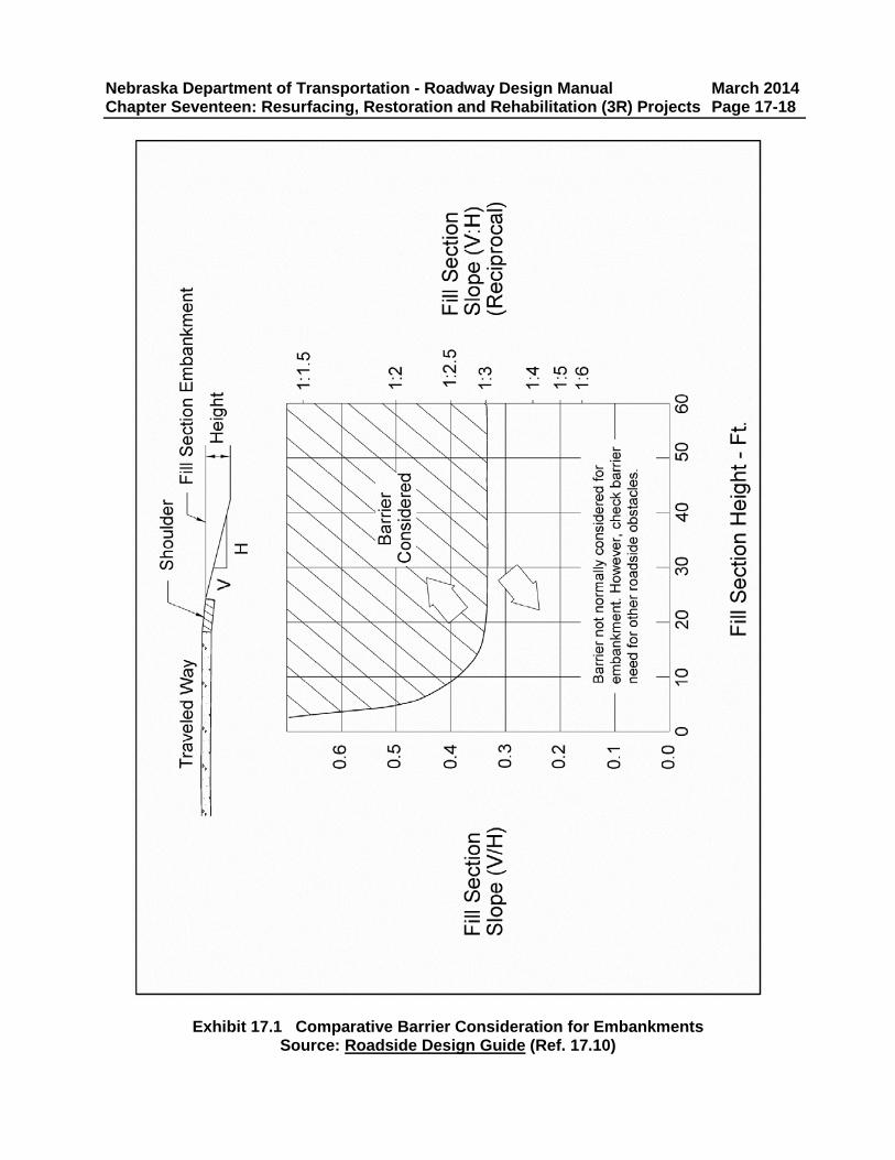
• Check existing fill slopes within the applicable 3R obstacle clearance for barrier desirability using EXHIBIT 17.1. The Unit Head or his/her designee should run a “Roadside Safety Analysis Program” (RSAP) cost effectiveness analysis to determine the desirability for barrier installation for other obstacles within the applicable 3R obstacle clearance.
• Culverts 36 inches or less in diameter and round-equivalent culverts 36 inches or less in width which have flared end sections and are within 45° of perpendicular to the direction of travel may be included within the fixed obstacle clearance if they meet 1:3 or flatter side slopes.
• The Unit Head or his/her designee should run a RSAP cost effectiveness analysis to determine the desirability for barrier installation for concrete box culverts and for culvert pipes with a diameter greater than 36 inches which are located within the applicable 3R obstacle clearance (See Chapter Nine: Guardrail and Roadside Barriers, Section 1.D).
Nebraska Department of Transportation - Roadway Design Manual March 2014 Chapter Seventeen: Resurfacing, Restoration and Rehabilitation (3R) Projects Page 17-17
• If a culvert is within the 3R fixed obstacle clearance and a cost-effectiveness analysis indicates that the culvert should be used in place without shielding (shielding is less than a 1:1 benefit to cost), a note should be placed in the project file stating: “Use in Place – Not cost effective to extend to fixed obstacle clearance or shield” (include the analysis data in the project file).
• Existing guardrail will not be removed without mitigating the hazard it is intended to shield. If the hazard has been mitigated, the guardrail may be removed with the approval of the Roadway Design Engineer.
• Existing guardrail which a cost-effectiveness analysis indicates is not required may not be removed without the written approval of the Roadway Design Engineer as evidenced by a Design Decision Document.
• When it is not possible to install sufficient roadside barrier length to shield either the clear zone distance or the fixed obstacle clearance, as appropriate (e.g. a railroad access drive which cannot be relocated and is within the development length of the guardrail), the designer will obtain the concurrence of the Unit Head and document the reason in the project file.
• A short radius guardrail may be used in rare situations with Unit Head approval (See Chapter Nine: Guardrail and Roadside Barriers, Section 7.A).
• The designer should use the tables found in Chapter Nine: Guardrail and Roadside Barriers, EXHIBIT 9.3, for runout length (Lr) values. Interpolate Lr values for speeds not listed in the table.
• A Guardrail End Treatment Type I (See Chapter Nine: Guardrail and Roadside Barriers, Section 4.A) should be installed to minimize earthwork and to avoid buying right-of-way on projects where right-of-way is not being purchased for other features of the project.
• The area behind the roadside barrier (either new installation or existing) will be evaluated for the required barrier deflection (See Chapter Nine: Guardrail and Roadside Barriers, EXHIBIT 9.6) and cleared as necessary.
• Whenever practicable and acceptable, cable guardrail should be installed at the locations that warrant a roadside barrier, including culvert locations.
• See Chapter Nine: Guardrail and Roadside Barriers for typical guardrail designs.
Nebraska Department of Transportation - Roadway Design Manual March 2014 Chapter Seventeen: Resurfacing, Restoration and Rehabilitation (3R) Projects Page 17-18
Nebraska Department of Transportation - Roadway Design Manual March 2014 Chapter Seventeen: Resurfacing, Restoration and Rehabilitation (3R) Projects Page 17-19 Americans with Disabilities Act (ADA): The NDOT has adopted the guidance in the 2011 Draft Public Rights-of-Way Accessibility Guidelines (PROWAG) (Ref. 17.6), issued by the Public Right-of-Way Access Advisory Committee (PROWAAC) (http://www.access-board.gov/). Facilities for the handicapped may be made to meet local requirements if those requirements meet or exceed NDOT policy. Curb ramps compliant with PROWAG (Ref. 17.6) will be required as specified in Chapter Sixteen: Pedestrian and Bicycle Facilities, Section 8.
• A “curb ramp” is a transition from the sidewalk to the gutterline of the crosswalk consisting of a ramp with a grade which is between 5% and 8.3% inclusive in the direction of pedestrian travel (the roadway designer is advised to design new curb ramps to an 8% maximum slope, whenever possible, for construction tolerance).
• A “blended transition” connects a sidewalk and a crosswalk with a grade of less than 5% in the direction of pedestrian travel. A blended transition will hereafter be referred to as a curb ramp and will be built using the curb ramp plan (See the Standard Plans, Ref. 17.9).
• The 2009 Nebraska Code, Chapter 60 Motor Vehicles defines a crosswalk as:
1. “That part of a roadway at an intersection included within the connections of the lateral lines if the sidewalks on opposite sides of such roadway measured from the curbs or, in the absence of curbs, from the edge of the roadway; or
2. Any portion of a roadway at an intersection or elsewhere distinctly designated by competent authority and marked for pedestrian crossing by lines, signs, or other devices.”
• City/Village representatives should be invited to attend the plan-in-hand to discuss
handicapped accessible routes and known accessibility needs, both when the project is complete and temporarily during construction.
• Existing curb ramps will be reviewed for compliance with PROWAG (Ref. 17.6):
1. Running slope will be 8.3% maximum in the direction of pedestrian travel. 2. Cross slope will be 2% maximum perpendicular to the direction of pedestrian
travel. 3. A 4 feet minimum curb ramp width. 4. A 15 feet maximum curb ramp length. 5. A 4 feet x 4 feet minimum landing area at the top of the curb ramp, which has a
2% maximum slope in any direction. A 5 feet dimension is required for wheel chair foot rest swing if the landing area is adjacent to a vertical obstruction.
6. Detectable warning panels are required when a sidewalk meets the highway, street, and signalized driveway where a vehicle is not intending to stop; they are not required on alleys and driveways, these are stop controlled or stop implied.
7. The presence and correct installation of detectable warning panels (truncated domes) will be verified. The detectable warning panels shall contrast visually with the adjacent gutter, street, or sidewalk (either darker or lighter).
a. Detectable warning panels will be cast-in-place when built with a new curb
Nebraska Department of Transportation - Roadway Design Manual March 2014 Chapter Seventeen: Resurfacing, Restoration and Rehabilitation (3R) Projects Page 17-20
b. When a surface applied detectable warning panel is used on an existing curb ramp the bid pay item is “Detectable Warning Panel”.
8. A transition of the curb ramp to the sidewalk, gutter, and street must be free of
abrupt changes in height (no vertical changes over 0.25 inch). 9. The counter slope of the gutter or street at the foot of a curb ramp will be 5%
maximum, perpendicular to the direction of pedestrian travel, for a distance of 2 feet as measured from the base of the curb ramp or landing edge at the street.
10. New sidewalk will be constructed only as required to match into the existing sidewalk, not to exceed 15 feet in length.
• Non-compliant curb ramps will be upgraded or reconstructed to current NDOT guidance
(see Chapter Sixteen: Pedestrian and Bicycle Facilities, Section 8) and PROWAG (Ref. 17.6) standards.
• An exemption to the above requirements for PROWAG (Ref. 17.6) compliant curb ramps may be granted if:
1. The curb ramp/blended transition has been constructed to the standards to the
maximum extent possible, 2. It is “technically infeasible” to construct a curb ramp or blended transition which
meets all of the standards, and 3. There is an accessible alternate route approved by the municipality.
• “Technically infeasible” is defined by the Department of Justice in the 2010 ADA Standards
for Accessible Design as “…or because other existing physical or site constraints prohibit modification or addition of elements, spaces, or features that are in full and strict compliance with the minimum requirements.” (emphasis original to DOJ)
• An exemption to the construction of a curb ramp requires the Roadway Design Engineer’s written approval in the project file. This exemption letter will document which aspects of the curb ramp were not built to the standards and why it is technically infeasible to meet all of the requirements of PROWAG (Ref. 17.6).
• If curb ramps are not provided, the designer must document in the plan-in-hand report or in a decision document in the project file (that there are no pedestrian facilities crossing the area of the project that will be altered.
• The designer will verify that raised medians in the urban section of a project adhere to PROWAG (Ref. 17.6) standards, providing pedestrian access across the street from curb ramp to curb ramp.
• Marked crosswalks shall be a minimum 6 feet wide. • The maximum cross-slope at a yield or stop controlled crosswalk shall be 2%. • The maximum cross-slope at a crosswalk that is not yield or stop controlled is 5%. • The cross-slope of a mid-block crosswalk may be warped to match the street grade. • The maximum running slope of a crosswalk, measured in the direction of pedestrian travel,
is 5%. • If traffic signals are being modified, the designer will coordinate the alteration/inclusion of
accessible pedestrian signals at crosswalks with Traffic Engineering (See the Nebraska Department of Transportation Operating Instruction 60-10, “ADA Accessibility Requirements in Transportation Projects”, Appendix B, “Selected NDOT Operating Instructions).
Nebraska Department of Transportation - Roadway Design Manual March 2014 Chapter Seventeen: Resurfacing, Restoration and Rehabilitation (3R) Projects Page 17-21
• If the project includes the resurfacing of on-street parking, the project should be reviewed to determine if it is possible to provide ADA parking (See PROWAG, Ref. 17.6, Sections R214 and R309).
• For ADA cost sharing information see Chapter Sixteen: Pedestrian and Bicycle Facilities, Section 13 and DOT-OI 60-11, “Municipal Cost Sharing” (Appendix B, “Selected NDOT Operating Instructions”).
• For ADA access during construction see Chapter Sixteen: Pedestrian and Bicycle Facilities, Section 12.
• For additional information, see Chapter Sixteen: Pedestrian and Bicycle Facilities and the Nebraska Department of Transportation Operating Instruction 60-10, “ADA Accessibility Requirements in Transportation Projects” (Appendix B, “Selected NDOT Operating Instructions).
Bridges:
• Guardrail connections and bridge rail on the project will be evaluated and, if necessary, upgraded to current criteria. The designer should request a determination of the acceptability of the bridge rail by Bridge prior to the plan-in-hand field inspection.
• If the project includes an overlay of the bridge deck, the bridge rail will be a minimum 29 inches in height.
Railroads:
• Work on railroad right-of-way must conform to Title 415, Nebraska Administrative Code, Chapter 6 (Highway-Rail Crossings – Construction, Repair and Maintenance) and requires a special provision prepared by the Railroad Liaison Office in the Intermodal Planning Division.
• The designer should e-mail the Intermodal Planning Division Railroad Liaison Engineer with the Project C.N., Project No., Designer, and Designer’s Phone Number for the initiation of the “Railroad Project Information Sheet” (Form DR-95) after the plan-in-hand.
• For PS&E turn-in, the designer should compute separate quantities for the work which is on railroad right-of–way (See Chapter Twelve: Cost Estimating & Funding, Section 1.E).
Lighting:
• The designer should request a review of state highway junctions for lighting warrants from the Roadway Design Lighting Unit (Lighting) before the plan-in-hand.
• Refer to DOT-OI 60-11, “Municipal Cost Sharing” (Appendix B, “Selected NDOT Operating Instructions”) for cost sharing information.
• See Chapter Ten: Miscellaneous Design Issues, Section 10, for additional information. Temporary Roads:
• See Chapter Fourteen: Traffic, Section 6.
Nebraska Department of Transportation - Roadway Design Manual March 2014 Chapter Seventeen: Resurfacing, Restoration and Rehabilitation (3R) Projects Page 17-22 Wetland Impacts and Environmental Permits:
• The designer will provide sufficient information to the Environmental Program Manager in PDD to determine if wetland delineation is required (e.g. culvert extensions or grading).
• See Chapter Thirteen: Planning and Project Development, Section 4, for further information.
Erosion Control
• See the Drainage Manual (Ref. 17.7), Chapter Two: Erosion and Sediment Control. Seeding:
• Type B seeding for an overlay project should be based on the width of the estimated disturbance. Generally, seeding equipment works in 4 feet increments so an overlay project may only require a 4 feet or 8 feet width of Type B seeding (See Chapter Two: Erosion and Sediment Control, Section 6.A.1 of the Drainage Manual, Ref. 17.7, for further information).
Cost Sharing:
• See the Nebraska Dept. of Roads Operating Instruction 60-11, “Municipal Cost Sharing” (Appendix B, “Selected NDOT Operating Instructions”).
Nebraska Department of Transportation - Roadway Design Manual March 2014 Chapter Seventeen: Resurfacing, Restoration and Rehabilitation (3R) Projects Page 17-23 3. REFERENCES 17.1 American Association of State Highway and Transportation Officials, A Policy on Design
Standards Interstate System, Washington, D.C., 2005. 17.2 American Association of State Highway and Transportation Officials, A Policy on
Geometric Design of Highways and Streets (the Green Book), Washington, D.C., 2011. 17.3 Board of Public Roads Classifications and Standards, Nebraska Minimum Design
Standards (MDS), Current Edition. (http://www.roads.nebraska.gov/business-center/lpa/boards-liaison/design-standards/) 17.4 Transportation Research Board, National Research Council, Special Report 214:
Designing Safer Roads – Practices for Resurfacing, Restoration, and Rehabilitation (TRB SR-214), Washington, D.C., 1987
17.5 Nebraska Department of Transportation, Design Process Outline (DPO), Current Edition (http://www.roads.nebraska.gov/business-center/design-consultant/) 17.6 Public Right-of-Way Access Advisory Committee (PROWAAC), “2011 Draft Public
17.7 Nebraska Department of Transportation, Drainage Design and Erosion Control Manual
(Drainage Manual), Current Edition (http://www.roads.nebraska.gov/business-center/design-consultant/rd-manuals/)
17.8 Title 23 of the “Code of Federal Regulations” (23 CFR 625)
(http://www.access.gpo.gov/nara/cfr/waisidx_02/23cfrv1_02.html) 17.9 Nebraska Department of Transportation, Standard/Special Plans Book, Current Edition.
(http://www.roads.nebraska.gov/business-center/design-consultant/stand-spec-manual/) 17.10 American Association of State Highway and Transportation Officials, Roadside Design
Nebraska Department of Transportation - Roadway Design Manual March 2014 Chapter Seventeen: Resurfacing, Restoration and Rehabilitation (3R) Projects Page 17-24