Page 1
8/8/2019 Chapter%201_Introduction%20n%20Basic%20Laws
http://slidepdf.com/reader/full/chapter201introduction20n20basic20laws 1/12
1/18/2011
1
Chapter 1 (Basic Laws)Chapter 1 (Basic Laws)
Contents – Kirchhoff's Law
– Series, parallel and series-parallel circuits
– Voltage and current division
– Introduction to Wye-Delta transformation
2Prepared by: Miss Rafidah_FKE_UiTM
Learning Outcome Week2
– Able to define Ohm’s Law and Kirchhoff's Laws
– Able to simplify circuit using series-parallel
simplification technique
– Able to apply Voltage and Current Division Rules – Able to use Y-∆ and ∆ -Y transformation
3Prepared by: Miss Rafidah_FKE_UiTM
Nodes, Branches and Loops
• Branch represents a single element such as a
voltage source or a resistor.
4Prepared by: Miss Rafidah_FKE_UiTM
Page 2
8/8/2019 Chapter%201_Introduction%20n%20Basic%20Laws
http://slidepdf.com/reader/full/chapter201introduction20n20basic20laws 2/12
1/18/2011
2
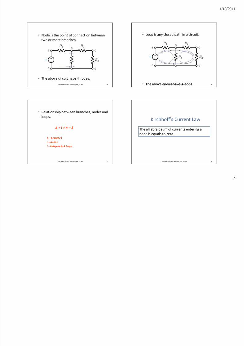
• Node is the point of connection between
two or more branches.
• The above circuit have 4 nodes.
5Prepared by: Miss Rafidah_FKE_UiTM
• Loop is any closed path in a circuit.
• The above circuit have 3 loops. 6Prepared by: Miss Rafidah_FKE_UiTM
• Relationship between branches, nodes and
loops.
b = l + n – 1
b – branches
n - nodes
l – independent loops
7Prepared by: Miss Rafidah_FKE_UiTM
Kirchhoff’s Current Law
8
The algebraic sum of currents entering a
node is equals to zero
Prepared by: Miss Rafidah_FKE_UiTM
Page 3
8/8/2019 Chapter%201_Introduction%20n%20Basic%20Laws
http://slidepdf.com/reader/full/chapter201introduction20n20basic20laws 3/12
1/18/2011
3
Kirchhoff current law (KCL) states that the algebraicsum of currents entering a node is zero. Or,
The sum of current entering a node = the sum of current leaving the node.
Based on KCL we can write the current eq. for allnode in a circuit.
Ex.:
9
Ia Ib
Ic
IdIe
Try to write down the current equation
base on KCL…
Prepared by: Miss Rafidah_FKE_UiTM
• Remember!!!
10
Sum current in = sum current out….(KCL).
Therefore:
Ia + Ic = Ib+ Id + Ie +
or
Ia + Ic – Ib – Id – Ie = 0
Prepared by: Miss Rafidah_FKE_UiTM
11Prepared by: Miss Rafidah_FKE_UiTM
Kirchhoff’s Voltage Law
12
The algebraic sum of all the voltages around
any closed path, in a circuit equals zero
Prepared by: Miss Rafidah_FKE_UiTM
Page 4
8/8/2019 Chapter%201_Introduction%20n%20Basic%20Laws
http://slidepdf.com/reader/full/chapter201introduction20n20basic20laws 4/12
1/18/2011
4
Applying KVL around the loop
20V
2
3
+ V1 -
+
V 2
-i
Applying KVL around the loop gives
-20 +V1 -V2 = 0
13Prepared by: Miss Rafidah_FKE_UiTM 14Prepared by: Miss Rafidah_FKE_UiTM
15Prepared by: Miss Rafidah_FKE_UiTM
Find the currents and voltages in the
circuit
Applying Ohm’s Law and
Kirchhoff’s Law
V1=8i1, V2=3i2, V3=6i3 ----(1)
At node ‘a’, KCL gives,
i1 = i2+i3 ----(2)
Applying KVL gives,
-30 + V1 + V2 = 0
-30 + 8i1 + 3i2= 0
i1= (30-3i2)/8 ----(3)
-V2 + V3 = 0 ---(4)
V2 = V3
+
V 3
-
+
V
2 -
16Prepared by: Miss Rafidah_FKE_UiTM
Page 5
8/8/2019 Chapter%201_Introduction%20n%20Basic%20Laws
http://slidepdf.com/reader/full/chapter201introduction20n20basic20laws 5/12
1/18/2011
5
We express V1 and V2 in terms of i1 and i2 asequ (1), therefore equ (4) becomes
6i3 = 3i2, i3 = i2/2 ----(5)
Substitute equ 3 and 5 into 2 gives
(30-3i2)/8 – i2 – i2/2 = 0
i2 = 2 ASo i1=3A, i3=1A, V1=24V, V2=6V, V3=6V
17Prepared by: Miss Rafidah_FKE_UiTM
Resistors in Series
A series circuit provides only one path for
current between two points so that the
current is the same through each series
resistor.
18Prepared by: Miss Rafidah_FKE_UiTM
Current in a Series Circuit
The current is the same through all points in a
series circuit. The current through each
resistor in a series circuit is the same as the
current through all the other resistors that arein series with it.
19Prepared by: Miss Rafidah_FKE_UiTM
Total Series Resistance
The total resistance of a series circuit is equalto the sum of the resistances of eachindividual series resistor.
20Prepared by: Miss Rafidah_FKE_UiTM
Page 6
8/8/2019 Chapter%201_Introduction%20n%20Basic%20Laws
http://slidepdf.com/reader/full/chapter201introduction20n20basic20laws 6/12
1/18/2011
6
Series Resistance FormulaFor any number of individual resistors
connected in series, the total resistance is the
sum of each of the individual values.
RT = R1 + R2 + R3 + . . . + Rn
21Prepared by: Miss Rafidah_FKE_UiTM
Voltage Sources in SeriesWhen two or more voltage sources are in series, the
total voltage is equal to the algebraic sum (including
polarities of the sources) of the individual source
voltages.
22Prepared by: Miss Rafidah_FKE_UiTM
Power in a Series Circuit
The total amount of power in a series resistive
circuit is equal to the sum of the powers in
each resistor in series.
PT = P1 + P2 + P3 + . . . + Pn
23Prepared by: Miss Rafidah_FKE_UiTM
Resistors in Parallel
Each current path is called a branch.
A parallel circuit is one that has more than onebranch.
24Prepared by: Miss Rafidah_FKE_UiTM
Page 7
8/8/2019 Chapter%201_Introduction%20n%20Basic%20Laws
http://slidepdf.com/reader/full/chapter201introduction20n20basic20laws 7/12
Page 8
8/8/2019 Chapter%201_Introduction%20n%20Basic%20Laws
http://slidepdf.com/reader/full/chapter201introduction20n20basic20laws 8/12
1/18/2011
8
Two Resistors in Parallel• The total resistance for two resistors in
parallel is equal to the product of the two
resistors divided by the sum of the two
resistors.
RT = R1R2/(R1 + R2)
29Prepared by: Miss Rafidah_FKE_UiTM
Current Sources in Parallel
The total current produced by all current sourcesis equal to the algebraic sum of the individualcurrent sources.
30Prepared by: Miss Rafidah_FKE_UiTM
Power in Parallel Circuits
Total power in a parallel circuit is found by
adding up the powers of all the individual
resistors.
PT = P1 + P2 + P3 + . . . + Pn
31Prepared by: Miss Rafidah_FKE_UiTM
6Ω||3 Ω = (6 x 3)/(6+3)= 2Ω
1Ω+5Ω=6Ω
2Ω + 2Ω = 4 Ω
4Ω || 6Ω = 2.4Ω
Req = 4Ω + 2.4Ω + 8Ω
= 14.4Ω
Req
4
2
36
8
1
5
32Prepared by: Miss Rafidah_FKE_UiTM
Page 9
8/8/2019 Chapter%201_Introduction%20n%20Basic%20Laws
http://slidepdf.com/reader/full/chapter201introduction20n20basic20laws 9/12
1/18/2011
9
Determine Req
33
Ω4 Ω4 Ω4Ω4Ω4
Prepared by: Miss Rafidah_FKE_UiTM
Find the equivalent resistance at terminal
a-b for each networks
34
Ω4
Ω4
Ω8
Ω4
Ω8
Prepared by: Miss Rafidah_FKE_UiTM
Find the equivalent resistance at
terminal a-b for each networks
35Prepared by: Miss Rafidah_FKE_UiTM
Find the equivalent resistance at terminal
a-b for each networks
36Prepared by: Miss Rafidah_FKE_UiTM
Page 10
8/8/2019 Chapter%201_Introduction%20n%20Basic%20Laws
http://slidepdf.com/reader/full/chapter201introduction20n20basic20laws 10/12
1/18/2011
10
Voltage-divider circuitVs = V1 + V2
= iR1 + iR2
i = Vs / (R1 + R2)
37
V1 = iR1
= Vs [R1/ (R1+ R2)]
V2 = iR2
= Vs [R2/ (R1+ R2)]
Prepared by: Miss Rafidah_FKE_UiTM
Find Va
38Prepared by: Miss Rafidah_FKE_UiTM
Current-divider circuit
V = i1R1 =i2R2
= [(R1*R2)/ (R1+R2)] is
39
i1 = V/R1 = [R2/(R1 + R2)] is
i2 = V/R2 = [R1/(R1 + R2)] is
Prepared by: Miss Rafidah_FKE_UiTM
Find i
40Prepared by: Miss Rafidah_FKE_UiTM
Page 11
8/8/2019 Chapter%201_Introduction%20n%20Basic%20Laws
http://slidepdf.com/reader/full/chapter201introduction20n20basic20laws 11/12
1/18/2011
11
Find i
41Prepared by: Miss Rafidah_FKE_UiTM
a) Find the no-load value of V0 incircuit shown
b) Find V0 when RL is 450KΩ
c) How much power is dissipatedin the 30KΩ resistor if the loadterminals are accidentallyshort-circuited?
d) What is the maximum power
dissipated in the 50KΩ resistor.
42Prepared by: Miss Rafidah_FKE_UiTM
Find the power
dissipated in the 6Ω
resistor
43Prepared by: Miss Rafidah_FKE_UiTM
Determine V 0
and i in the circuit shown
44Prepared by: Miss Rafidah_FKE_UiTM
Page 12
8/8/2019 Chapter%201_Introduction%20n%20Basic%20Laws
http://slidepdf.com/reader/full/chapter201introduction20n20basic20laws 12/12
1/18/2011
12
Introduction to Y and ∆
45Prepared by: Miss Rafidah_FKE_UiTM 46
∆ - Y Conversion
Rc Rb Ra
RbRc R
++=1
Rc Rb Ra
RcRa R
++=2
Rc Rb Ra
RaRb R
++=3
Prepared by: Miss Rafidah_FKE_UiTM
47
1
133221
R
R R R R R R Ra
++=
Y - ∆ Conversion
2
133221
R
R R R R R R Rb ++=
3
133221
R
R R R R R R Rc
++=
Prepared by: Miss Rafidah_FKE_UiTM
Obtain the equivalent resistance
Rab for the circuit shown and find i
48
+
-
Prepared by: Miss Rafidah_FKE_UiTM