International Journal of Scientific Engineering and Applied Science (IJSEAS) – Volume-2, Issue-7,July 2016 ISSN: 2395-3470 www.ijseas.com 74 CHARACTERISTIC BEHAVIOUR OF ADDITIVE ON MECHANICAL AND MICROSTRUCTURES OF CAST IRON W.A.AjibolaP 1* PJ.O.A AkintadeP 1 P G.W IbrahimP 1 P 1 PDepartment of Mechanical Engineering. The Federal Polytechnic Ilaro, Ogun state, Nigeria. P * P Email :[email protected]. Abstract This paper focus on the characteristic behavior of additives at various percentages to instill special properties on cast iron .Each additive was added between 1-5% at maximum to bring the best properties. Silicon carbide, silicon, magnesium and nickel were used as additives at maximum of 20% in addition of total composition. A total of six (6) samples were studied (A- E) and a control sample, mechanical properties and microstructures shows tremendous improvement in the area of strength from 205.45Mpa (control sample) to 226.62Mpa (sample E) increasing energy for fracture from 0.8937 to 1.167897 (Joules), hardness increases from 83 to 105 on Rockwell scale. Impact energy reduces as a result of shocking load, Show little resistance to impact load. The microstructural study reveal that the additives were uniformly distributed which resulted to an increase in tensile strength from 207.65Mpa to 226.62Mpa. Keywords: Impact, Resistance ,Microstructure ,Characteristics ,Shocking load 1.0 Introduction Iron carbon alloys containing less than 1.9wt%c are classified as steels and those containing more than 2wt%C are classified as cast iron. Cast Iron is made when pig iron is melted in small cupola furnace similar to the blast furnace in design and pour into moulds to make casting. Cast iron, like steel, is essentially an alloy of iron and carbon but the carbon content is much higher, usually in the range 2.5-4.0%. Substantial quantities of silicon, manganese, sulphur and phosphorus may also be present. The high carbon content makes the alloy brittle so that it cannot be mechanically formed. However, the high carbon content imparts very good casting characteristics so that intricate shapes are easily achieved by this method. In steel the carbon exists only as the compound FeR 3 RC (cemetite) but in cast iron the carbon may exist either as cementite or as free carbon in the form of graphite.
Transcript
International Journal of Scientific Engineering and Applied Science (IJSEAS) – Volume-2, Issue-7,July 2016 ISSN: 2395-3470
www.ijseas.com
74
CHARACTERISTIC BEHAVIOUR OF ADDITIVE ON MECHANICAL AND MICROSTRUCTURES OF CAST IRON
W.A.AjibolaP
1* PJ.O.A AkintadeP
1P G.W IbrahimP
1
P
1 PDepartment of Mechanical Engineering. The Federal Polytechnic Ilaro, Ogun state, Nigeria.
This paper focus on the characteristic behavior of additives at various percentages to instill special properties on cast iron .Each additive was added between 1-5% at maximum to bring the best properties. Silicon carbide, silicon, magnesium and nickel were used as additives at maximum of 20% in addition of total composition. A total of six (6) samples were studied (A-E) and a control sample, mechanical properties and microstructures shows tremendous improvement in the area of strength from 205.45Mpa (control sample) to 226.62Mpa (sample E) increasing energy for fracture from 0.8937 to 1.167897 (Joules), hardness increases from 83 to 105 on Rockwell scale. Impact energy reduces as a result of shocking load, Show little resistance to impact load. The microstructural study reveal that the additives were uniformly distributed which resulted to an increase in tensile strength from 207.65Mpa to 226.62Mpa.
Iron carbon alloys containing less than 1.9wt%c are classified as steels and those containing more than 2wt%C are classified as cast iron. Cast Iron is made when pig iron is melted in small cupola furnace similar to the blast furnace in design and pour into moulds to make casting.
Cast iron, like steel, is essentially an alloy of iron and carbon but the carbon content is much higher, usually in the range 2.5-4.0%. Substantial quantities of silicon, manganese, sulphur and phosphorus may also be present. The high carbon content makes the alloy brittle so that it cannot be mechanically formed. However, the high carbon content imparts very good casting characteristics so that intricate shapes are easily achieved by this method.
In steel the carbon exists only as the compound FeR3RC (cemetite) but in cast iron the carbon may exist either as cementite or as free carbon in the form of graphite.
International Journal of Scientific Engineering and Applied Science (IJSEAS) – Volume-2, Issue-7,July 2016 ISSN: 2395-3470
www.ijseas.com
75
1600
1400
1200
1000
800
ferrite
(a)
600
0 1 2 3 4 5 6
CARBON CONTENT (wt%)
Fig 1 .0 The cast iron portion of the iron –carbon phase diagram(Material science and metallurgy 4 P
thP ed polallack prentice Hall,1988.
At ambient temperatures the microstructure of cast iron may consist of mixtures of pearlite and cementite, pearlite and graphite. The type of microstructure that is actually produced depends on several factors including the composition of iron, the cooling, rate casting and nature of heat treatment applied to the finished casting. In particular, a slow rate of cooling, a high carbon content and a high silicon concentration all favour the formation of graphite rather than cementite in the iron are usally classified as malleable, grey and spheroidal irons.
White cast iron derives its name from the white, crystalline crack surface observed when a casting fractures. After fractured, cracks pass straight through due to its carbide impurities. An improved form of white cast iron is chilled cast iron (Hinggins,1993). White cast iron is hard and brittle and cannot be machined easily. It is the only member of the cast iron family in which carbon is present as carbide. Most white cast irons contain less than 4.3% carbon, with low silicon contents to inhibit the precipitation of carbon as graphite. As a result of graphite absence, it has a light appearance. The presence of different carbides makes white cast iron extremely hard and abrasion resistant, but very brittle (Jiyang, 2009). The microstructure contains massive cementite (white) and pearlite. It also contains interdendritic cementite (white), which sometimes has a Widmanstiitten (“spiky”) appearance. Austenite forms as the proeutectic constituent before the eutectic reaction (liquid transforms to austenite and cementite) and later transforms to pearlite and cementite upon cooling below the eutectic temperature [JIyang 2000].
3.0 Experimental Procedure
3.1 Patterns and Materials for Pattern making.
This is a duplicate of the specimen to be produced it is a basic requirement in the production of sand castings. They are made slightly larger than the required final product to compensate for the shrinkage of the metal after it solidifies and cools in the mould.
MOULD MAKING
Sand mould use for making small and medium size casting are provided in a moulding box.
Basically, the mould comprise of two main parts. The cope (know as upper half) and lower part called the “Drag.The cope is filled with moulding sand and rammed firmly into shape in the same format as in the making of the drag.
Liquid Liquid +
Cementite or Liquid
+ Austenite Austenite (y)
Austenite + cementite
Or
Pearlite + cementite
Pearlite + graphite
Ferrite + graphite
Liquid + &
International Journal of Scientific Engineering and Applied Science (IJSEAS) – Volume-2, Issue-7,July 2016 ISSN: 2395-3470
www.ijseas.com
76
MELTING AND POURING
The cupola has good operational efficiency. The operating efficiency of the cupola is higher than any other foundry melting techniques due to the counter movement of the heading gases in respect to the charge. The chemical composition of the melt can be controlled even under conditions of continuous melting.
The cast iron scraps are charged into the furnace (Required composition). The furnace is fired for about 6 – 8 hours. Until scraps are completely molten. The additives are charged into the furnace and left for about 1hrs for the alloy to mix completely. The pot is completely removed from the furnace and the content if discharged into the mould. The velocity with which the molten metal fills the mould is determined by the cross sectional area of the gating system and the mould pouring rate. Too slow a mould parts allowing surface oxidation. Too high a pouring rate caused by two large a gating system causes sand inductions by erosion, particularly in green sand molding and turbulence the first metal in the pouring basin and down the sprue usually has some turbulence which carries slag into the runner. To avoid slag in the casting the runner should extend past the last gate to trap the slag .(Sakwa et al.,1980 ).
Gating arrangement may also be made at the top or bottom of the cavity. Gating is used for simple design in cast iron but not for non-ferrous alloys since excessive dross would be formed by the agitation
FETTLING: After casting, shake the dry sand, remove all gates and rises. Then clean the casting surface sand blasting
CASTING DEFECT: The following factors are usually responsible for producing defects in casting.A cold shut casting is one in which a definite discontinuity exists due to imperfect fusion where two streams of metal have converge. This defect may have the appearance of a crack or seam with smooth rounded edges (Burns ,1986)
MATERIALS AND PREPARATION.
In the course of this research the cast iron and additives was sourced from the (FIIRO) Federal Institute of Industrial Research Oshodi Lagos Nigeria.
Table 1.1 Chemical composition of cast iron
ELEMENT %COMPOSITION ELEMENT %COMPOSITION
Fe 95% Mn 0.015%
C 3.2% Mg 0.05%
Si 1.45% Ni 0.005%
P 0.0045% S 0.34%
WEIGHING AND CUTTING OF SAMPLE
Additives such as silicon, silicon carbide and Nickel are required in small quantities, the additives are grinded into pebbles and further to powdery form to enhance easy weighing .The weighing was done using digital weighing machine.
Table 1.2 Percentage of additives used for samples
SAMPLES Si SiC Ni Mg Cast
iron
SAMPLE E 1% 1% 1% 1% 96% 100%
SAMPLE D 2% 2% 2% 2% 92% 100%
International Journal of Scientific Engineering and Applied Science (IJSEAS) – Volume-2, Issue-7,July 2016 ISSN: 2395-3470
www.ijseas.com
77
SAMPLE C 3% 3% 3% 3% 88% 100%
SAMPLE B 4% 4% 4% 4% 84% 100%
SAMPLE A 5% 5% 5% 5% 80% 100%
CONTROL SAMPLE -- -- --- --- 100% 100%
CHARACTERIZATION
The tensile, hardness and Impact test were conducted on the samples as well as the metallographic examination.
TENSILE TEST.
The Tensile test was carried out on the UTM (Universal Tensile Machine).The samples were first machined according to ASTM standard,(60mm by 6mm diameter) after machining, the dead weight is fixed to the UTM with the aid of the jaw gripping at both ends.
The machine is connected to the computer (VDU) and various data required such as stress, strain, load, extension are programmed.The operating pump used in exerting tensile force operated electrically until the test piece fractures.
HARDNESS TEST
The hardness test was performed on the Rockwell Hardness Machine using the Rockwell Hardness Carbide ball (1/16). The carbide ball indenter is forced into the surface of the material being tested under the action of an applied force .The indenter causes localized deformation of the material.
When the force is removed it leaves a permanent impression on the surface of the material, the dimension of this impression is used in the determination of the hardness number.. The values of hardness test were recorded.
IMPACT TEST. The Charpy impact machine was used for the impact test rigid pendulum is allowed to fall from a known height and to strike the test sample at the lowest point of the swing.The amount of energy that was absorbed in breaking the samples are recorded. Materials of low toughness are notch sensitive, smooth, un-notched samples are often used in the impact testing of low toughness material (John ,1992). The values obtained from the test are recorded.
METALLOGRAPHIC EXAMINATION.
The Specimens for the optical metallographic were prepared using standard techniques .After grinding, a mixture of 2%Nital was used as etchant .The Microstructure of the Specimen were examine using a digital Metallurgical Microscope (Magnification x100).
4.0 RESULT AND DISCUSSION
The results obtained from various experiments performed on the different Samples and their Implications.
Table 2.1 Ultimate tensile Strength with Strain.
SAMPLE UTS(MPa) STRAIN (%)
E 226.62 2.13
D 222.53 2.17
C 221.75 2.19
B 210.45 2.25
A 207.65 2.35
International Journal of Scientific Engineering and Applied Science (IJSEAS) – Volume-2, Issue-7,July 2016 ISSN: 2395-3470
www.ijseas.com
78
CONTROL 205.45 2.38
Table 2.2 Variation of Energy at Fracture and load at Fracture
SAMPLES ENERGY AT MAX LOAD(J) LOAD AT FRACTURE(KN)
E 1.16789 4.94
D 1.11568 4.74
C 1.02570 4.51
B 1.00124 4.34
A 0.97650 3.96
CONTROL 0.89750 3.85
Table 2.3 Rockwell Hardness
SPECIMEN SAMPLE ROCKWELL HARDNESS(HRBN)
E 105
D 105
C 102
B 100
A 96
CONTROL 83
Table 2.4 Impact Test (Charpy)
SPECIMEN SAMPLE IMPACT TEST(JOULES)
E 4.740
D 4.280
C 4.190
B 3.390
A 3.314
CONTROL 5.424
International Journal of Scientific Engineering and Applied Science (IJSEAS) – Volume-2, Issue-7,July 2016 ISSN: 2395-3470
www.ijseas.com
79
Fig 2.1 The graph of stress/strain
Fig 2.2 The graph of energy against load
STRESS/SRAIN GRAPH
200
205
210
215
220
225
230
2.1 2.15 2.2 2.25 2.3 2.35 2.4
%STRAIN
STR
ES
S(M
Pa)
UTS(MPa)
GRAPH OF ENERGY/LOAD
0
0.2
0.4
0.6
0.8
1
1.2
1.4
0 2 4 6
LOAD (KN)
ENE
ENERGY BY MAX
International Journal of Scientific Engineering and Applied Science (IJSEAS) – Volume-2, Issue-7,July 2016 ISSN: 2395-3470
www.ijseas.com
80
Fig 2.3 The graph of hardness value
ROCKWELL HARDNESS(HRBN)
0
20
40
60
80
100
120
0 2 4 6 8
E D C B A CONTROL
HARD
NESS
VAL
UE
ROCKWELLHARDNESS(HRBN)
International Journal of Scientific Engineering and Applied Science (IJSEAS) – Volume-2, Issue-7,July 2016 ISSN: 2395-3470
www.ijseas.com
81
Fig 2.4 The graph of impact strength
MICROGRAPHY OF SAMPLES
IMPACT GRAPH
0
1
2
3
4
5
6
0 2 4 6 8
A B C D E CONTROL
IMPACT
IMPACT TEST(JOULES)
International Journal of Scientific Engineering and Applied Science (IJSEAS) – Volume-2, Issue-7,July 2016 ISSN: 2395-3470
www.ijseas.com
82
Fig 3.1 SAMPLE A
Fig 3.2 SAMPLE B
Fig 3.3 SAMPLE C
International Journal of Scientific Engineering and Applied Science (IJSEAS) – Volume-2, Issue-7,July 2016 ISSN: 2395-3470
www.ijseas.com
83
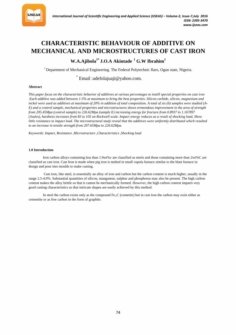
Fig 3.4 SAMPLE D
Fig 3.5 SAMPLE E
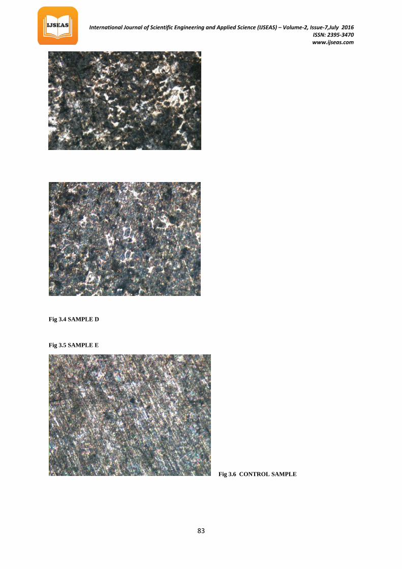
Fig 3.6 CONTROL SAMPLE
International Journal of Scientific Engineering and Applied Science (IJSEAS) – Volume-2, Issue-7,July 2016 ISSN: 2395-3470
www.ijseas.com
84
Discussion
The test results shows that sample E containing 1%Si,1%SiC ,1%Ni and 1%Mg possess a maximum strength of 226.62MPa with a minimum strain of 2.13.The micrograph of sample E shows a uniform distribution of additives around the graphite flakes.The nodular structure of additive around graphite flakes is responsible for the increase in tensile ,hardness and impact strength.
Sample D of 2%Si ,2%SiC, 2%Ni and 2%Mg with a tensile strength of 222.52MPa with a strain 2.17.The volume of additive is increased and the distribution of the nodular phase is increased which also give an appreciable high strength.
Sample C of 3%Si,3%SiC,3%Ni and 3%Mg with a tensile strength of 221.53MPaand a strain 2.19.The Micrograph shows the distribution of additives ,the reduction in hardness is due to the fact that the concentration of cementite has been reduced.
Sample B of 4%Si, 4%SiC, 4%Ni 4 and 4%Mg with a strength of 210.45Mpa and a strain of 2.25.The hardness value reduced considerably due to the fact that the proportion of cementite has been reduced and the sample shows less resistance to impact load.
Sample A of 5%Si,5%SiC,5%Niand 5%Mg with a tensile strength of 207.65Mpa and a strain of 2.35.The micrograph shows a sparse distribution of free carbon or cementite with high volume fraction of additives ,the sample has the maximum strain but there is reduction in the hardness value.
The hardness of the first and second volume fraction of additive shows no decrease, but little reduction in Strength.
The result of the impact test shows that as the volume of additive increases the samples shows little resistance to shock loads.
Findings
With proof based on the results from the experiment carried out the following were confirmed • Introduction of addictive impassive both the mechanical and microstructure of cast iron. • The increase in the volume fraction of additive increase the tensile strength of the material. • The hardness increases as the volume of the additive increases ,the additives lower the resistance to impact load
5.0 Conclusion and Recommendation
The cast iron is used in circumstances where a very high resistance is desirable .For instance where violent crushing of rocks and minerals are required. Naturally ,the very high carbon concentration of typical cast irons causes difficulties by introducing brittle martensite in the heat affected zone of the weld.it is therefore necessary to preheat to a temperature of about 450P
0Pc followed by slow cooling after welding ,in order to avoid cracking.
REFERENCES
Alexander.B, (2011), Graded coal - Its role in iron casting production from greensand systems, China foundry publisher, vol.8, no 2 pp235-238
Brick Pense and Gordon (1971) ,Material science and Engineering.
Charles Newey and Graham Weaver (1991) , material processing.
George Laird ,Richard Gundlach and Klaus Rohrig (2000),Abrasion –resistance cast iron Handbook,ASM international ISBN 0-87433-224-9
International Journal of Scientific Engineering and Applied Science (IJSEAS) – Volume-2, Issue-7,July 2016 ISSN: 2395-3470
www.ijseas.com
85
Higgins, R. P. (1993): Engineering Metallurgy 6th Edition, Suffolk and Lortnolls limited, CornwallEnglandPp.274-280.
John Gloag and Dereck Bridgwater,(1984) A History of cast iron in Architecture London.
John V.B (1992), Introduction to Engineering Materials, Macmillan 3 P
rdP Edition.
Kenneth .M. Rall et.al. (1976) , introduction to Material Science and Engineering
Olagoke S.A (2006),Engineering Materials and Metal Forming first edition SAO Ventures Nigeria
Sakwa,.W, Jura,. J,. Sakwa. J,(1980), Wear resistance cast iron. Part I. Cast iron. Wyd. ZG STOP, Kraków. ]
Jiyang Z (2009): Colour metallography of white cast iron, china foundry publisher, Vol.8 No 3 pp 337-349
International Journal of Scientific Engineering and Applied Science (IJSEAS) – Volume-2, Issue-7,July 2016 ISSN: 2395-3470
www.ijseas.com
86
White cast iron derives its name from the white, crystalline crack surface observed when a casting fractures. After fractured, cracks pass straight through due to its carbide impurities. An improved form of white cast iron is chilled cast iron [1]. White cast iron is hard and brittle and cannot be machined easily. It is the only member of the cast iron family in which carbon is present as carbide. Most white cast irons contain less than 4.3% carbon, with low silicon contents to inhibit the precipitation of carbon as graphite. As a result of graphite absence, it has a light appearance. The presence of different carbides makes white cast iron extremely hard and abrasion resistant, but very brittle [2]. The microstructure contains massive cementite (white) and pearlite. It also contains interdendritic cementite (white), which sometimes has a Widmanstiitten (“spiky”) appearance. Austenite forms as the proeutectic constituent before the eutectic reaction (liquid transforms to austenite and cementite) and later transforms to pearlite and cementite upon cooling below the eutectic temperature [2]. Carbonaceous materials are materials that are very rich in carbon content, at least, about sixty to eighty per cent (
International Journal of Scientific Engineering and Applied Science (IJSEAS) – Volume-2, Issue-7,July 2016 ISSN: 2395-3470
www.ijseas.com
87
Higgins, R. P. (1993): Engineering Metallurgy 6th Edition, Suffolk and Lortnolls limited, Cornwall, England Pp.274-280. [2] Jiyang Z (2009): Colour metallography of white cast iron, china foundry publisher, Vol.8 No 3 pp 337-349 [3] Alexander.B, (2011): Graded coal - Its role in iron casting production from greensand systems, China foundry publisher, vol.8, no 2 pp235-238 [4] Deepak C, (2008): Green sand Management – Role & Application of Carbonaceous Additives and Concept of total Carbon in a Green Sand System, 68th world foundry congress, pp. 127-132 [5] Burns T.A. (1986): The Foseco Foundry man’s textbooks Pergaman Press, Oxford. [6] Sakwa,.W, Jura,. J,. Sakwa. J,(1980): Wear resistance cast iron. Part I. Cast iron. Wyd. ZG STOP, Kraków. [7] Huggett P, Ben-Nissan.B (2007), Development of a low melting point white cast iron for use in composite alloy manufacture, materials forum, vol. 31,pp.16-23. [8] Hillert M. and Steinhauser H.(1960): The Structure of White Cast Iron Jemont Ann, 144, Pp 520-559 [9] Mukherjees P.C. (2003): Mould section material, properties and testing fundamental of metal casting technology, pp703-754. [10] Scott .S, (
] Higgins, R. P. (1993): Engineering Metallurgy 6th Edition, Suffolk and Lortnolls limited, Cornwall, England Pp.274-280. [2] Jiyang Z (2009): Colour metallography of white cast iron, china foundry publisher, Vol.8 No 3 pp 337-349 [3] Alexander.B, (2011): Graded coal - Its role in iron casting production from greensand systems, China foundry publisher, vol.8, no 2 pp235-238 [4] Deepak C, (2008): Green sand Management – Role & Application of Carbonaceous Additives and Concept of total Carbon in a Green Sand System, 68th world foundry congress, pp. 127-132 [5] Burns T.A. (1986): The Foseco Foundry man’s textbooks Pergaman Press, Oxford. [6] Sakwa,.W, Jura,. J,. Sakwa. J,(1980): Wear resistance cast iron. Part I. Cast iron. Wyd. ZG STOP, Kraków. [7] Huggett P, Ben-Nissan.B (2007), Development of a low melting point white cast iron for use in composite alloy manufacture, materials forum, vol. 31,pp.16-23. [8] Hillert M. and Steinhauser H.(1960): The Structure of White Cast Iron Jemont Ann, 144, Pp 520-559 [9] Mukherjees P.C. (2003): Mould section material, properties and testing fundamental of metal casting technology, pp703-754. [10] Scott .S, (2000): The